Language selection

Search

Patent 2352341 Summary

Third-party information liability

Some of the information on this Web page has been provided by external sources. The Government of Canada is not responsible for the accuracy, reliability or currency of the information supplied by external sources. Users wishing to rely upon this information should consult directly with the source of the information. Content provided by external sources is not subject to official languages, privacy and accessibility requirements.

Claims and Abstract availability

Any discrepancies in the text and image of the Claims and Abstract are due to differing posting times. Text of the Claims and Abstract are posted:

  • At the time the application is open to public inspection;
  • At the time of issue of the patent (grant).
(12) Patent: (11) CA 2352341
(54) English Title: MAGNETIC RETAINER FOR A REPLACEABLE WEAR PLATE
(54) French Title: DISPOSITIF DE RETENUE MAGNETIQUE POUR PLAQUE D'USURE REMPLACABLE
Status: Expired
Bibliographic Data
(51) International Patent Classification (IPC):
  • B65D 90/08 (2006.01)
  • B65D 90/04 (2006.01)
  • B65G 11/16 (2006.01)
  • B65G 15/62 (2006.01)
  • B65G 19/28 (2006.01)
(72) Inventors :
  • MILES, DAVID ROGER (Canada)
(73) Owners :
  • FULLER INDUSTRIAL CORPORATION (Not Available)
(71) Applicants :
  • MILES, DAVID ROGER (Canada)
  • RAMPAGE VENTURES INC. (United Kingdom)
(74) Agent: OYEN WIGGS GREEN & MUTALA LLP
(74) Associate agent:
(45) Issued: 2003-04-29
(86) PCT Filing Date: 1999-12-01
(87) Open to Public Inspection: 2000-06-08
Examination requested: 2001-05-22
Availability of licence: N/A
(25) Language of filing: English

Patent Cooperation Treaty (PCT): Yes
(86) PCT Filing Number: PCT/CA1999/001154
(87) International Publication Number: WO2000/032500
(85) National Entry: 2001-05-22

(30) Application Priority Data:
Application No. Country/Territory Date
09/204,326 United States of America 1998-12-02

Abstracts

English Abstract


A wear plate retainer (10) having upper and lower layers (10B, 10A). The lower
layer is formed of a relatively soft, shock-absorbent material. The upper
layer is formed of a relatively hard, impact and abrasion resistant material.
A plurality of magnets (20) are embedded in the upper layer to removably
magnetically retain a wear plate (12) atop the upper layer. A pair of pole
pieces (22, 24) are positioned on opposed sides of each magnet and embedded in
the upper layer. The pole pieces extend above the magnet, protecting it from
impact forces. The pole pieces focus the magnetic field forces emanating from
the magnet. The magnets are arranged in rows, with adjacent poles of adjacent
pairs of magnets in adjacent pairs of the rows having alternate polarity. The
rows are parallel to one another and extend transversely to the direction (16)
in which material (14) flows across the wear plate.


French Abstract

La présente invention concerne un dispositif de retenue (10) pour plaque d'usure muni d'une couche supérieure et d'une couche inférieure (10B, 10A). La couche inférieure est formée d'une matière relativement molle amortissant les chocs. La couche supérieure est formée d'une matière relativement dure résistant aux chocs et à l'abrasion. Plusieurs aimants (20) sont encastrés dans la couche supérieure afin de retenir magnétiquement une plaque d'usure amovible (12) située au-dessus de la couche supérieure. Deux pôles (22, 24) sont placés sur les côtés opposés de chaque aimant et encastrés dans la couche supérieure. Les pôles s'étendent au-dessus de l'aimant, le protégeant des chocs. Les pôles font converger les forces du champ magnétique émanant de l'aimant. Les aimants sont disposés en rangées, les pôles voisins de paires d'aimants voisins situés dans des paires adjacentes de rangées ayant une polarité alternée. Les rangées sont parallèles les unes aux autres et s'étendent transversalement dans la direction (16) par laquelle la matière (14) s'écoule à travers la plaque d'usure.

Claims

Note: Claims are shown in the official language in which they were submitted.


-12-

WHAT IS CLAIMED IS:

1. A wear plate retainer for magnetically retaining a replaceable,
ferrous wear plate on said wear plate retainer during passage of
abrasive material over said wear plate, said wear plate retainer
characterized by:
(a) an upper layer and a lower layer, said upper layer formed
of a relatively hard, impact and abrasion resistant material
and said lower layer formed of a relatively soft, shock-
absorbent material; and,
(b) a plurality of magnets embedded within said upper layer to
removably magnetically retain said wear plate atop said
upper layer.

2. A wear plate retainer as defined in claim 1, further characterized
by, for each one of said magnets, a pair of pole pieces embedded
within said upper layer, said pole pieces respectively positioned
on opposed sides of said each one of said magnets and extending
above said each one of said magnets.

3. A wear plate retainer as defined in claim 2, further characterized
by a plurality of shock-absorbing recesses formed in said lower
layer.

4. A wear plate retainer as defined in claim 2, wherein said magnets
are arranged in a plurality of rows, with adjacent poles of adjacent
pairs of said magnets within adjacent pairs of said rows having
alternate polarity.


-13-

5. A wear plate retainer as defined in claim 4, wherein said rows are
respectively parallel to one another and extend transversely to a
direction of flow of said abrasive material across said wear plate.

6. A wear plate retainer as defined in claim 4, wherein said pole
pieces have upper ends substantially flush with a top face of said
upper layer.

7. A wear plate retainer as defined in claim 2, wherein said lower
layer is formed of 55A durometer polyurethane material and said
upper layer is formed of 80A durometer polyurethane material.

8. A wear plate retainer as defined in claim 2, wherein said soft,
shock-absorbent material and said hard, impact and abrasion
resistant material are elastomeric materials.

9. A method of magnetically retaining a replaceable, ferrous wear
plate in position on a wear plate retainer during passage of abra-
sive material over said wear plate, said method characterized by:
(a) forming a lower retainer layer of a relatively soft, shock-
absorbent material;
(b) forming an upper retainer layer of a relatively hard, impact
and abrasion resistant material atop said lower layer;
(c) embedding a plurality of magnets within said upper layer;
and,
(d) placing said wear plate atop said upper layer for magnetic
retention of said wear plate in said position by said mag-
nets.

10. A method as defined in claim 9, further characterized by, for each
one of said magnets, embedding a pair of pole pieces within said


-14-

upper layer on opposed sides of each one of said magnets and
extending above said each one of said magnets.

11. A method as defined in claim 10, further characterized by forming
a plurality of shock-absorbing recesses in said lower layer.

12. A method as defined in claim 10, further characterized by arrang-
ing said magnets in a plurality of rows, with adjacent poles of
adjacent pairs of said magnets within adjacent pairs of said rows
having alternate polarity.

13. A method as defined in claim 12, further characterized by arrang-
ing said rows respectively parallel to one another and extending
transversely to a direction of flow of said abrasive material across
said wear plate.

14. A method as defined in claim 12, further characterized by posi-
tioning said pole pieces with upper ends of said pole pieces sub-
stantially flush with a top face of said upper layer.

15. A method as defined in claim 10, further characterized by forming
said lower layer of 55A durometer polyurethane material and
forming said upper layer of 80A durometer polyurethane material.

16. A method as defined in claim 10, further characterized by forming
said upper layer and said lower layer of elastomeric materials.

17. A wear plate retainer, characterized by are elastome;ric material
having a plurality of magnets embedded within said elastomeric
material to removably magnetically retain a wear plate atop said
elastomeric material.


-15-

18. A wear plate retainer as defined in claim 17, further characterized
by, for each one of said magnets, a pair of pole pieces embedded
within said elastomeric material, said pole pieces respectively
positioned on opposed sides of said each one of said magnets and
extending above said each one of said magnets.

19. A wear plate retainer as defined in claim 18, further characterized
by a plurality of shock-absorbing recesses formed in said
elastomeric material.

20. A wear plate retainer as defined in claim 18, wherein said mag-
nets are arranged in a plurality of rows, with adjacent poles of
adjacent pairs of said magnets within adjacent pairs of said rows
having alternate polarity.

21. A wear plate retainer as defined in claim 20, wherein said rows
are respectively parallel to one another and extend transversely to
a direction of flow of said abrasive material across said wear
plate.

22. A wear plate retainer as defined in claim 20, wherein said pole
pieces have upper ends substantially flush with a top face of said
elastomeric material.

23. A wear plate retainer as defined in claim 17, wherein said
elastomeric material is 55A durometer polyurethane material.

24. A wear plate retainer as defined in claim 17, wherein said
elastomeric material is 80A durometer polyurethane material.


-16-

25. A method of magnetically retaining a ferrous wear plate in posi-
tion for passage of abrasive material over said wear plate, said
method characterized by:
(a) forming a layer of elastomeric material;
(b) embedding a plurality of magnets within said elastomeric
material; and,
(c) placing said wear plate atop said elastomeric material for
magnetic retention of said wear plate in said position by
said magnets.

26. A method as defined in claim 25, further characterized by, for
each one of said magnets, embedding a pair of pule pieces within
said elastomeric material on opposed sides of said each one of said
magnets and extending above said each one of said magnets.

27. A method as defined in claim 26, further characterized by forming
a plurality of shock-absorbing recesses in said elastomeric mate-
rial.

28. A method as defined in claim 26, further characterized by arrang-
ing said magnets in a plurality of rows, with adjacent poles of
adjacent pairs of said magnets within adjacent pairs of said rows
having alternate polarity.

29. A method as defined in claim 28, further characterized by arrang-
ing said rows respectively parallel to one another and extending
transversely to a direction of flow of said abrasive material across
said wear plate.


-17-

30. A method as defined in claim 28, further characterized by posi-
tioning said pole pieces with upper ends of said pole pieces sub-
stantially flush with a top face of said elastomeric material.

31. A method as defined in claim 26, wherein said elastomeric mate-
rial is 55A durometer polyurethane material.

32. A method as defined in claim 26, wherein said elastomeric mate-
rial is 80A durometer polyurethane material.

33. Wear resistance apparatus characterized by:
(a) an upper layer and a lower layer, said upper layer formed
of a relatively soft, shock-absorbent material and said lower
layer formed of a relatively hard, impact and abrasion
resistant material;
(b) a plurality of magnets embedded within said lower layer;
(c) for each one of said magnets, a pair of pole pieces embed-
ded within said lower layer, said pole pieces respectively
positioned on opposed sides of said each one of said mag-
nets and extending above said each one of said magnets;
and,
(d) a plurality of shock-absorbing recesses formed in said lower
layer.

34. Apparatus as defined in claim 33, wherein said magnets are
arranged in a plurality of rows, with adjacent poles of adjacent
pairs of said magnets within adjacent pairs of said rows having
alternate polarity.


-18-

35. Apparatus as defined in claim 34, wherein said rows are respec-
tively parallel to one another and extend transversely to a direc-
tion of flow of an abrasive material across said apparatus.

36. Apparatus as defined in claim 34, wherein said pole pieces have
upper ends substantially flush with a top face of said lower layer.

37. Apparatus as defined in claim 33, wherein said upper layer is
formed of 55A durometer polyurethane material and said lower
layer is formed of 80A durometer polyurethane material.

38. Apparatus as defined in claim 33, wherein said soft, shock-absor-
bent material and said hard, impact and abrasion resistant material
are elastomeric materials.

39. A method of cushioning fragile moving materials, characterized
by:
(a) forming an upper layer of a relatively soft, shock-absorbent
material;
(b) forming a lower layer of a relatively hard, impact and
abrasion resistant material beneath said upper layer;
(c) embedding a plurality of magnets within said lower layer;
and,
(d) placing said lower layer on a ferrous surface over which
said fragile materials are to be moved, to magnetically
attach said lower layer to said ferrous surface and to posi-
tion said upper layer to cushion impacts of said fragile
materials against said upper layer.

40. A method as defined in claim 39, further characterized by, for
each one of said magnets, embedding a pair of pole pieces within


-19-

said lower layer on opposed sides of said each one of said mag-
nets and extending above said each one of said magnets.

41. A method as defined in claim 40, further characterized by arrang-
ing said magnets in a plurality of rows, with adjacent poles of
adjacent pairs of magnets within adjacent pairs of said rows
having alternate polarity.

42. A method as defined in claim 41, further characterized by arrang-
ing said rows respectively parallel to one another and extending
transversely to a direction of flow of said fragile material.

43. A method as defined in claim 41, further characterized by posi-
tinning said pole pieces with upper ends of said pole pieces sub-
stantially flush with a bottom face of said lower layer.

44. A method as defined in claim 40, further characterized by forming
said upper layer of 55A durometer polyurethane material and
forming said lower layer of 80A durometer polyurethane material.

45. A method as defined in claim 40, further characterized by forming
said upper layer and said lower layer of elastomeric materials.

46. Wear resistance apparatus, characterized by:
(a) an elastomeric material having a plurality of magnets em-
bedded within said elastomeric material to removably mag-
netically attach said apparatus to a ferrous object;
(b) for each one of said magnets, a pair of pole pieces embed-
ded within said elastomeric material, said pole pieces re-
spectively positioned on opposed sides of said each one of


-20-

said magnets and extending above said each one of said
magnets; and,
(c) a plurality of shock-absorbing recesses formed in said
elastomeric material.

47. Apparatus as defined in claim 46, wherein said magnets are
arranged in a plurality of rows, with adjacent poles of adjacent
pairs of said magnets within adjacent pairs of said rows having
alternate polarity.

48. Apparatus as defined in claim 47, wherein said rows are respec-
tively parallel to one another and extend transversely to a direc-
tion of flow of an abrasive material across said apparatus.

49. Apparatus as defined in claim 47, wherein said pole pieces have
upper ends substantially flush with a top face of said elastomeric
material.

50. Apparatus as defined in claim 46, wherein said elastomeric mate-
rial is 55A durometer polyurethane material.

51. Apparatus as defined in claim 46, wherein said elastomeric mate-
rial is 80A durometer polyurethane material.

52. A method of resisting abrasion of a ferrous object by an abrasive
material passing over said object, said method characterized by:
(a) forming a layer of an elastomeric material;
(b) embedding a plurality of magnets within said elastomeric
material; and,


-21-

(c) placing said layer on said object, to magnetically attach said
layer to said object and to position said layer for passage of
said abrasive material over said layer.

53. A method as defined in claim 52, further characterized by, for
each one of said magnets, embedding a pair of pole pieces within
said layer on opposed sides of said each one of said magnets and
extending above said each one of said magnets.

54. A method as defined in claim 53, further characterized by arrang-
ing said magnets in a plurality of rows, with adjacent poles of
adjacent pairs of said magnets within adjacent pairs of said rows
having alternate polarity.

55. A method as defined in claim 54, further characterized by arrang-
ing said rows respectively parallel to one another and extending
transversely to a direction of flow of said abrasive material.

56. A method as defined in claim 54, further characterized by posi-
tioning said pole pieces with opposed ends of said pole pieces
respectively substantially flush with top and bottom faces of said
layer.

57. A method as defined in claim 54, further characterized by forming
said layer of 55A durometer polyurethane material.

58. A method as defined in claim 54, further characterized by forming
said layer of 80A durometer polyurethane material.


-22-

59. Apparatus as defined in claim 46, wherein said magnets are
further embedded within opposed first and second sides of said
elastomeric material.

60. Apparatus as defined in claim 59, further characterized by a
reduced thickness region of said elastomeric material extending
between said first and second sides of said elastomeric material.

61. Apparatus as defined in claim 60, wherein said plurality of mag-
nets is further characterized by a first one of said magnets embed-
ded within said first side of said elastomeric material and a second
one of said magnets embedded within said second side of said
elastomeric material.

62. Apparatus as defined in claim 60, wherein said plurality of mag-
nets is further characterized by a first plurality of said magnets
embedded within said first side of said elastomeric material and a
second plurality of said magnets embedded within said second side
of said elastomeric material, said magnets arranged in rows, with
adjacent poles of adjacent pairs of said magnets within adjacent
pairs of said rows having alternate polarity.

63. Apparatus as defined in claim 60, further characterized by an
elastomeric pad removably positionable between said ferrous
object and said apparatus.

64. Apparatus as defined in claim 60, further characterized by a
support plate having one side fixed to said elastomeric pad, a stem
having one end fixed to an opposite side of said support plate, and
a cap fixed to an opposite end of said stem, said cap removably
insertable through an aperture in said reduced thickness region.


-23-

65. Apparatus as defined in claim 60, wherein said elastomeric mate-
rial is 55A durometer polyurethane material.

66. Apparatus as defined in claim 60, wherein said elastomeric mate-
rial is 80A durometer polyurethane material.

Description

Note: Descriptions are shown in the official language in which they were submitted.


WO 00/32500 PCT/CA99/01154
MAGNETIC RETAINER FOR A REPLACEABLE WEAR PLATE
Technical Field
This application pertains to a retainer having a replaceable,
magnetically retained wear plate for absorbing wear in discharge chutes,
conveyors and other locations exposed to moving abrasives such as
cement, sand, gravel, etc. Magnets embedded in the retainer are sand-
wiched between pole pieces which focus the magnetic field and protect
the magnets .
Back r;~; ound
Wear absorbing plates are commonly used to line chutes, hoppers,
trunnions, chain runs, loading decks and other locations which are
exposed to excessive wearing. For example, hardened wear plates are
used to line surfaces over which cement, sand, gravel, or other abrasives
flow. The objective is to reduce the rate of wear caused by such
abrasives. Ordinarily, wear plates are formed of high grade steels having
better abrasion resistant characteristics than the materials forming
adjacent portions of the chute, hopper, trunnion, etc. The wear plate
thus extends the useful life of the chute, hopper, etc.
Wear plates are normally affixed at wear points by welding,
bolting, riveting, clamping or other relatively permanent means. Such
forms of attachment can make it difficult, inconvenient, time consuming,
labour intensive and/or expensive to remove and replace a wear plate
which has worn out. Particular difficulties can arise if grinders or cutting
torches are required to remove a worn out wear plate, for example if
there is a hazard of fire or explosion in the adjacent surroundings, as is
common in installations such as grain elevators, oil or gas refineries, saw
CA 02352341 2001-05-22

1$-x9_''000 _ _ _ __ _ _ _ _ _ _ _ _ _ _ _._ __ _ _ _
2C1'. Vl)V : I:I'A-MUENCHEN U2 : 18- 9- 0 : ?u : SH f~04- ets7 ~.urs1--. +~.~
H:~ '~;jJay~4b:~ . ~, y.
~l CA 0099011 ~~
-2-
mills, etc. Moreover, wear plates are often located in cramped working
spaces which increase the difficulty of removing and replacing a worn out
wear plate.
The present invention overcomes the foregoing difficulties by
S providing a wear plate which can be firmly magnetically retained at a
wear point yet readily removed and replaced therefrom. The magnetized
wear plate retainer also has impact absorbing characteristics which can
improve the wear plate's capability to resist wear.
United States Patent No. 4,340,616 discloses a method for
decreasing surface wear by incorporating magnetic material into the
surface to provide a sacrificial wear-resistant surfac~c. For example, the
wear resistant capability of a pipe which conveys an abrasive slurry can
be improved. But this does not address the aforementioned difficulties
encountered in removing and replacing a worn out wear plate. United
States Patent No. 4,997,025 discloses a magnetically retained wear plate
for the molding space of a flask-less molding machine, but lacking an
impact absorbing capability as aforesaid.
~ummar,Lr,of I venti n
The invention provides, in one embodiment, .a wear plate retainer
having upper and lower layers. The upper layer is formed of a relatively
hard, impact and abrasion resistant material such as 80A durameter
polyurethane material. The lower layer formed of a relatively soft,
shock-absorbent material such as 55A durometer polyurethane material.
A plurality of magnets are embedded within the upper layer to rcmovably
and magnetically retain a wear plate atop the upper layer.
CA 02352341 2001-05-22 AMENDED SHEET

:C1': V()N:E;pA-'MUEUiCHEN 02__ _ _' 1B-. '-~- ~ ~ 20:5g__: EiO4 Ea$1 4~U81-~
+49 t39 ~:39944ES5:#~ 5
18-09-2000 - - -
CA 00990115
- 2.1 -
Pole pieces are embedded within the upper layer on apposite sides
of each magnet and extending above the magnets. '!'he pole pieces
protect the magnets frvm impact forces and focus the magnetic field
forces emanating from the magnets.
CA 02352341 2001-05-22 AMENDED SHEET


WO 00/32500 PCT/CA99/01154
-3-
The magnets are preferably arranged in rows, with adjacent poles
of adjacent pairs of magnets within adjacent rows having alternate polar-
ity. The rows are respectively parallel to one another and extend
transversely to a direction of material flow across the wear plate.
Advantageously, a plurality of shock-absorbing recesses can be
formed in the lower layer.
Another embodiment of the invention requires only a less
expensive, easily fabricated single layer of polyurethane material. The
single layer may be either a relatively hard, impact and abrasion resistant
material or a relatively soft, shock-absorbent material, depending upon
which material's characteristics are preferred in the application of
interest.
In a further embodiment, one may dispense with the wear plate and
employ only a dual layer apparatus having magnets embedded in the
IS lower layer. The apparatus is allowed to magnetically attach itself to a
ferrous surface such as a suitable portion of a discharge chute, hopper,
trunnion, etc, leaving the softer layer uppermost to cushion the impact of
a fragile moving material.
Still further embodiments of the invention employ only a single
layer apparatus having magnets embedded therein. Such apparatus can
be used as a "patch" to cover a worn region of a ferrous object such as
a cylindrical pipe wall.
Brief Description of Drawings
Figure 1 is a cross-sectional side elevation view of a retainer
having a replaceable, magnetically retained wear plate in accordance with
the present invention.
CA 02352341 2001-05-22


WO 00/32500 PCT/CA99/01154
-4-
Figure 2 is a perspective illustration of a portion of the preferred
retainer, with wear plate removed.
Figure 3 is a cross-sectional side elevation view of an alternate
embodiment of the invention which does not require a wear plate.
Figures 4A and 4B are respectively cross-sectional side elevation
and perspective illustrations of a single layer embodiment of the invention
which does not require a wear plate.
Figure 5 is schematic cross-sectional illustration of a worn pipe,
showing the embodiment of Figures 4A and 4B magnetically affixed to
the pipe's exterior wall as an abrasion-resistant patch to cover and seal
the pipe at the point of wear.
Figure 6 is similar to Figure 4B and further illustrates an abrasion-
resistant pad for improving the sealing capability of the invention.
Description
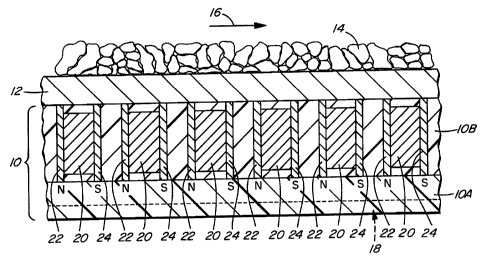
Figures 1 and 2 depict a retainer 10 for removably, magnetically
retaining a ferrous wear plate 12. Abrasive material 14 flows over wear
plate 12 in the direction indicated by arrow 16, gradually wearing wear
plate 12 to the point at which it must be replaced. Retainer 10 can be
fixed in a discharge chute, hopper, trunnion or other location exposed to
abrasive material 14 by bolting, screwing, welding, adhesive or other
suitable attachment means. Since wear plate 12 is removably magneti-
cally attached to retainer 10 as hereinafter explained, wear plate 12 can
easily be removed and replaced when it wears out without any need for
removal or replacement of retainer 10.
Retainer 10 is made up of two separate layers 10A, lOB consisting
of different types of material. Each material may be an elastomer such
CA 02352341 2001-05-22


WO 00/32500 PCT/CA99/01154
-5_
as polyurethane. Lower layer l0A is preferably formed of relatively soft
55A durometer polyurethane material which provides a shock absorbing
capability. Upper layer lOB is preferably formed of a harder, impact and
abrasion resistant 80A durometer polyurethane material. Suitable 55A
and 80A durometer polyurethane material is manufactured by the
chemical division of Uniroyal Inc., Naugatuck, Connecticut, under
product designations Uniroyal'~'~' Vibrathane'''M 8050 and Uniroyal~
Vibrathane''b'' 8083 respectively. Optionally, a plurality of parallel,
grooved recesses 18 (Figure 2) can be formed in the bottom face of
retainer 10. Recesses I8 improve the shock-absorbing capability of lower
layer l0A by allowing the portions of layer l0A surrounding the respect-
ive recesses 18 to flex into the recesses.
A plurality of magnetic strips 20 (hereafter "magnets"), each
having a north pole "N" and a south pole "S" are embedded within upper
layer IOB. Each magnet 20 is sandwiched between a pair of impact-
resistant pole pieces 22, 24. Pole pieces 22, 24 are preferably steel
plates having a height dimension greater than the height dimension of
magnets 20. This allows pole pieces 22, 24 to be embedded within upper
layer lOB with the upper ends of pole pieces 22, 24 substantially flush
with the top face of retainer 10 and with magnets 20 protectively recessed
between their respective pole pieces. Pole pieces 22, 24 accordingly
protect magnets 20 from impact forces to which retainer 10 can
commonly be subjected during normal operation of the chute, hopper,
etc. in which retainer 10 is mounted. Pole pieces 22, 24 also serve to
focus the magnetic field forces emanating from magnets 20.
Within each pair of longitudinally adjacent rows of magnets,
adjacent magnets in each row are oriented to alternate the polarities of
CA 02352341 2001-05-22


WO 00/32500 PCT/CA99/01154
-6-
that magnet pair. Thus, the south ("S ") pole of each magnet 20 in one
row is oriented to face the north ("N") pole of the immediately adjacent
magnet in the next row, and vice versa. This orientation of magnets 20
assists in providing full magnetic field coverage over the top face of
retainer 10 while minimizing "dead spots" (i.e. regions of reduced
magnetic field coverage having reduced capability to magnetically attach
wear plate 12). Magnets 20 may be formed of a suitable magnetic
material, such as grade 5 ceramic.
As best seen in Figure 2, magnets 20 embedded within upper layer
lOB extend transversely to the direction 16 of material flow across wear
plate 12. This enhances the ability of retainer 10 to magnetically resist
possible sliding of wear plate 12 relative to retainer 10 due to forces
imparted to wear plate 12 by heavy abrasives moving across wear plate
12 at high speed.
Retainer 10 can be made by a molding process. For example, a
mold (not shown) having the desired shape may be constructed. The
mold is inverted, then magnets 20 and pole pieces 22, 24 are positioned
within the mold, in the same locations as described above in reference to
the completed retainer 10. Impact and abrasion resistant material in
liquified form is then poured into the mold over magnets 20 to form
upper layer IOB. Softer, shock-absorbent material in liquified form is
then poured into the mold to form lower layer 10A. A chemical bonding
action occurs at the interface between the two types of material, securely
bonding the two layers together. A mold cover formed with a series of
ribs is then secured atop the mold, to embed the cover's ribs in the softer
material and thereby form grooved recesses 18 in the bottom face of
CA 02352341 2001-05-22


WO 00/32500 PCT/CA99/01154
_ 7 _
retainer 10. After the liquified material hardens, the mold is opened and
the completed retainer removed therefrom.
In operation, retainer 10 is fixed in place at the wear point as
aforesaid, and wear plate 12 is laid atop retainer 10 to magnetically
attach wear plate 12 to retainer 10. Abrasive material 14 is then allowed
to flow across wear plate 12 in the direction of arrow 16. The shock
absorbent characteristics of retainer 10 assist in absorbing some of the
forces generated by repeated impact of material 14 with retainer 10,
somewhat reducing wear on wear plate 12 and prolonging its life.
Magnets 20 embedded within retainer 10 are protected from being
damaged by such impact forces by the aforementioned recessing of
magnets 20 within the hard material forming upper layer lOB and by
sandwiching each magnet between a protective pair of steel plate pole
pieces 22, 24.
If wear plate 12 becomes worn out, it can be replaced quickly,
easily and safely by inserting the tip of a pry bar (not shown) between the
magnetically attached faces of retainer 10 and wear plate 12 and applying
a downward force to the pry bar so as to break the force of magnetic
attraction exerted by magnets 20 and lift wear plate 12 clear of upper
layer 10B. The worn out wear plate 12 is then removed and a new wear
plate laid atop retainer 10 to magnetically attach the new wear plate to
the retainer. The pry bar can be inserted from any side of retainer 10,
thus enabling a workman to perform the removal operation from the most
conveniently accessible location.
The invention significantly reduces the time required to replace a
worn out wear plate, thus reducing equipment down time, and reducing
costs. The need for skilled labour and specialized removal equipment is
CA 02352341 2001-05-22


WO 00/32500 PCT/CA99/01154
_ g _
also reduced, as is the potential for damage or injury due to spark or
flame hazards during the removal operation. Further, less expensive
wear plate materials can be used, because worn out wear plates can be
replaced quickly and easily with the aid of the invention. By contrast,
prior art wear plates are commonly made of relatively expensive longer
lasting materials, due in part to the comparatively high cost of removing
and replacing such wear plates.
In some circumstances it may be preferable to dispense with wear
plate 12. For example, in the nickel smelting industry, relatively fragile
nickel "pucks" are transported via conveyors, hoppers, chutes, etc. The
pucks can be damaged if they are allowed to strike a non-absorptive
surface such as ferrous wear plate 12. Figure 3 depicts an alternate
embodiment of the invention which overcomes this problem by eliminat-
ing wear plate 12. Instead of Bxing retainer 10' in place by bolting, etc.
as described above, retainer 10' is inverted as shown in Figure 3 to allow
the harder layer l0B' to magnetically attach itself to a ferrous surface 1 A
such as a suitable portion of a discharge chute, hopper, trunnion, etc.
This leaves the softer layer l0A' uppermost to cushion the impact of
fragile material 3A. Although softer layer l0A' is not as well suited to
resist impact or abrasion as is harder layer lOB', it may in some cases be
preferable to invert retainer 10' as aforesaid to better exploit the shock
absorbing capability of softer layer l0A', for example in transporting
fragile materials as described above.
It is not always possible to accurately predict the wear pattern of
a part which is subject to abrasive wearing, nor are areas subject to wear
always readily accessible. It may be impractical, expensive, and/or
hazardous to counteract such wearing using conventional repair tech-
CA 02352341 2001-05-22


WO 00/32500 PCTJCA99/01154
-9-
piques such as welding, cutting, braising, bolting, wiring or taping. This
is especially so in the case of contoured surfaces which are subject to
abrasive wearing, such as cylindrical pipes used to convey abrasive
slurries or the like, discharge chutes, junctions, elbows, bends, twists, or
loops in piping, tubing or ducting, etc. The embodiment of the invention
depicted in Figures 4A, 4B, S and 6 is well suited to use in such
situations.
Figures 4A, 4B, 5 and 6 depict a flexible, wear-resistant "patch"
lOC consisting of a single layer of either hard or soft elastomeric
material. Magnets 20 and pole pieces 22, 24 are embedded within patch
lOC as previously described, except that a central, reduced width region
25A of elastomeric material extends between the opposed, wider left and
right (as viewed in Figures 4A, 4B, 5 and 6) side regions which contain
the embedded magnets. Reduced width region 25A contains no magnets
and is thus more flexible than the wider magnet-embedded side regions
of patch lOC. Flexibility is improved by using only one magnetic strip
on either side of region 25A, reducing the number of inflexible steel
plate pole pieces. As best seen in Figure 5, patch lOC is flexibly
conformed and magnetically attached to the outer surface of a contoured
20 ferrous member such as cylindrical pipe wall 27 to cover worn region 26,
which has become perforated due to continued passage of abrasive
material 14 along the pipe in the direction of arrow 16A.
The size and shape of patch lOC can be varied to accommodate
different host wear surfaces to accommodate factors such as the overall
dimensions of the host wear surface, the dimensions (or anticipated
dimensions) of the worn portion (eg. hole, perforation, crack, etc.) of the
host wear surface, the size and nature of abrasive material L4 which is
CA 02352341 2001-05-22


WO 00/32500 PCT/CA99/01154
- 10-
to be contained, the possibility that material 14 may be conveyed under
hydraulic or pneumatic pressure, etc. When flexibly conformed and
magnetically attached to pipe wall 27 to cover worn region 26 as
aforesaid, patch lOC seals pipe wall 27 to prevent escape of abrasive
material 14 through region 26. During affixation of patch lOC over worn
region 26, the opposed left and right (as viewed in Figures 4A, 4B, 5 and
6) sides of patch l OC are preferably forcibly drawn away from each other
as indicated by arrows "E" in Figure 5, to more closely conform reduced
width region 25A over worn region 26 and thereby improve the sealing
capability of patch lOC to further minimize escape of abrasive material
14 through worn region 26.
As seen in Figure 6, a relatively thin (approximately 0.5 to 1.0 cm
thick) flexible, abrasion-resistant, elastomeric pad 28 can be optionally
provided to further improve the sealing capability of patch IOC. In some
cases, an adhesive can be used to fx pad 28 to the exterior surface of
pipe wall 27 over worn region 26, prior to magnetic attachment of patch
lOC to pipe wall 27 as aforesaid. However, it may not always be
practical or convenient to use an adhesive to fix pad 28 to pipe wall 27.
In such cases, a prefabricated unit incorporating pad 28, plate 29, stem
30 and cap 31 can be used.
More particularly, one end of rigid stem 30 is pre-attached (i.e. by
welding) to a central surface portion of rigid plate 29. Enlarged, rigid
cap 31 is pre-attached (i.e. by welding) to the opposite end of stem 30.
An adhesive is then used to pre-attach plate 29 to a central surface
portion of elastomeric pad 28. In the field, the workman simply bores
a small hole (i.e. smaller than the diameter of cap 31) through reduced
width region 25A of the elastomeric material used to form patch lOC,
CA 02352341 2001-05-22


WO 00/32500 PCT/CA99/01154
-11-
then forces cap 31 and stem 30 upwardly (as viewed in Figure 6) through
the hole from one side of reduced width region 25A until cap 31 emerges
through the opposite side of reduced width region 25A. Enlarged cap 31
prevents casual, unintended withdrawal of stem 30 through the hole,
removably retaining pad 28 in position for sealing affixation over worn
region 26 when patch lOC is flexibly conformed and magnetically
attached to pipe wall 27 to cover worn region 26 as aforesaid. Pad 28
serves as a replaceable wear element.
Thus, instead of subjecting patch lOC to wearing by directly
affixing patch lOC over worn region 26, one may apply pad 28 between
patch lOC and worn region 26 by either of the above techniques. If pad
28 subsequently becomes worn by abrasive action of material 14, pad 28
can be removed, discarded and quickly and easily replaced with a fresh
pad. This is accomplished by inserting a pry bar to break the magnetic
forces attaching patch lOC to pipe wall 27, and removing patch IOC. If
pad 28 is coupled to plate 29, stem 30 and cap 31 as aforesaid, then
those elements are removed from pipe wall 27 together with patch l OC .
Plate 29 can then be pulled perpendicularly away from patch lOC to
forcibly withdraw cap 3I through the aforementioned hole. A replace-
ment prefabricated unit incorporating a fresh pad 28 is then removably
fixed to patch IOC, which can quickly and easily be replaced without any
need for tools, adhesives, etc. If pad 28 was originally adhesively
attached to pipe wall 27, then any portion of a pad 28 which may remain
affixed to pipe wall 27 is removed by peeling, grinding, etc. A
replacement pad 28 is then adhesively attached to pipe wall 27 and patch
lOC is again flexibly conformed and magnetically attached to pipe wall
27 over the new pad 28 to cover worn region 26.
CA 02352341 2001-05-22


tCV: \'011: La',1-A1Ui_NCHLN_ O? __ _ _v 18' '~- t) : ~0: W_-: _ 6l)4 E8,1
4081-1 +4~J 8.~ 13~J~~4.V5: # ti
18-09-2000 ~ _ _ _ .. _ _ _ _
CA 009901154
- 12-
As will be apparent to those skilled in the art in the light of the
foregoing disclosure, many alterations and modifications are possible in
the practice of this invention without departing from the scope thereof.
For example, instead of embedding magnets 20 in the harder 80A
durometer material one could reverse the two layers and embed magnets
20 in the softer SSA durometer material so as to better exploit the shock
absorbing capability of the softer material in particular situations. As
another example, although it will usually be preferable to employ a dual
layer retainer to ubtaim the combined benefits of impact and abrasion
resistance (via the harder 80A durorncter material) and shock absorption
(via the sofrer 55A durometer material), it will not always be necessary
to form retainer 10 (or 10') with two layers l0A aad lOB (or l0A' and
lOB'). In some cases it will be sufficient to eliminate either one of the
two layers. Thus, a single layer of harder 80A durometer material with
magnets 20 embedded therein can be employed if impact and abrasion
resistance are primary requisites, with shock absorption being relatively
unimportant. Conversely, a single Layer of softer 55A durometer
material with magnets 20 embedded therein can be employed if shock
absorption is a primary requisites, with impact and abrasion resistance
being relatively unimportant. In either case, single layer retainers will
tie less expensive and easier to fabricate than dual layer retainers of the
same size. Although patch lOC preferably uses only one magnetic strip
20 on either side of region 25A, multiple magnetic strips and pole pieces
can be used to improve the magnetic attachment capability of patch 14C,
if the resultant degradation in flexibility of patch lOC is acceptable.
CA 02352341 2001-05-22 AMENDED SHEET

Representative Drawing
A single figure which represents the drawing illustrating the invention.
Administrative Status

For a clearer understanding of the status of the application/patent presented on this page, the site Disclaimer , as well as the definitions for Patent , Administrative Status , Maintenance Fee  and Payment History  should be consulted.

Administrative Status

Title Date
Forecasted Issue Date 2003-04-29
(86) PCT Filing Date 1999-12-01
(87) PCT Publication Date 2000-06-08
(85) National Entry 2001-05-22
Examination Requested 2001-05-22
(45) Issued 2003-04-29
Expired 2019-12-02

Abandonment History

There is no abandonment history.

Payment History

Fee Type Anniversary Year Due Date Amount Paid Paid Date
Request for Examination $200.00 2001-05-22
Registration of a document - section 124 $100.00 2001-05-22
Application Fee $150.00 2001-05-22
Maintenance Fee - Application - New Act 2 2001-12-03 $50.00 2001-05-22
Registration of a document - section 124 $100.00 2001-09-11
Registration of a document - section 124 $100.00 2002-01-25
Registration of a document - section 124 $50.00 2002-07-05
Maintenance Fee - Application - New Act 3 2002-12-02 $100.00 2002-09-11
Advance an application for a patent out of its routine order $100.00 2002-10-07
Final Fee $300.00 2003-02-14
Maintenance Fee - Patent - New Act 4 2003-12-01 $100.00 2003-08-25
Maintenance Fee - Patent - New Act 5 2004-12-01 $200.00 2004-09-07
Maintenance Fee - Patent - New Act 6 2005-12-01 $200.00 2005-11-07
Maintenance Fee - Patent - New Act 7 2006-12-01 $200.00 2006-09-06
Maintenance Fee - Patent - New Act 8 2007-12-03 $200.00 2007-09-17
Registration of a document - section 124 $100.00 2008-05-12
Maintenance Fee - Patent - New Act 9 2008-12-01 $200.00 2008-09-19
Maintenance Fee - Patent - New Act 10 2009-12-01 $450.00 2010-05-05
Maintenance Fee - Patent - New Act 11 2010-12-01 $250.00 2010-11-09
Maintenance Fee - Patent - New Act 12 2011-12-01 $250.00 2011-10-26
Maintenance Fee - Patent - New Act 13 2012-12-03 $250.00 2012-09-11
Maintenance Fee - Patent - New Act 14 2013-12-02 $250.00 2013-08-22
Maintenance Fee - Patent - New Act 15 2014-12-01 $450.00 2014-09-03
Maintenance Fee - Patent - New Act 16 2015-12-01 $450.00 2015-10-23
Maintenance Fee - Patent - New Act 17 2016-12-01 $450.00 2016-08-23
Maintenance Fee - Patent - New Act 18 2017-12-01 $450.00 2017-11-30
Maintenance Fee - Patent - New Act 19 2018-12-03 $450.00 2018-11-23
Registration of a document - section 124 $100.00 2019-11-19
Owners on Record

Note: Records showing the ownership history in alphabetical order.

Current Owners on Record
FULLER INDUSTRIAL CORPORATION
Past Owners on Record
ACR GROUP INC.
MILES, DAVID ROGER
RAMPAGE VENTURES INC.
Past Owners that do not appear in the "Owners on Record" listing will appear in other documentation within the application.
Documents

To view selected files, please enter reCAPTCHA code :


To view images, click a link in the Document Description column. To download the documents, select one or more checkboxes in the first column and then click the "Download Selected in PDF format (Zip Archive)" or the "Download Selected as Single PDF" button.

List of published and non-published patent-specific documents on the CPD .

If you have any difficulty accessing content, you can call the Client Service Centre at 1-866-997-1936 or send them an e-mail at CIPO Client Service Centre.


Document
Description 
Date
(yyyy-mm-dd) 
Number of pages   Size of Image (KB) 
Claims 2002-11-20 12 474
Cover Page 2003-03-26 1 59
Description 2001-05-22 13 612
Claims 2001-05-22 13 463
Abstract 2001-05-22 1 76
Drawings 2001-05-22 5 158
Cover Page 2001-09-10 1 59
Representative Drawing 2001-09-06 1 22
Claims 2002-10-11 12 481
Prosecution-Amendment 2002-11-20 3 118
Correspondence 2003-02-14 1 35
Assignment 2008-05-12 6 243
Prosecution-Amendment 2002-11-06 2 35
Prosecution-Amendment 2002-10-11 14 547
Prosecution-Amendment 2002-10-17 1 12
Assignment 2002-07-05 3 165
Assignment 2001-05-22 4 243
PCT 2001-05-22 21 762
Assignment 2001-09-11 3 177
Assignment 2002-01-25 3 185
Prosecution-Amendment 2002-10-07 1 45