Note: Descriptions are shown in the official language in which they were submitted.
CA 02352421 2001-07-05
17TU-6018
STEAM TURBINE CONTROLLER HAVING METHOD AND
APPARATUS FOR PROVIDING VARIABLE FREQUENCY
REGULATION
BACKGROUND OF THE INVENTION
This invention relates to a control system for a turbine, and in
particular, for a steam turbine. The invention specifically relates to a
turbine speed controller that regulates the rotational speed and power
output(Ioad) of the turbine, especially during extended periods in which
the turbine is required to operate at a frequency other than its normal
frequency (speed) set-point.
Industrial and power steam turbines have control systems
("controllers") that monitor and control their operation. Traditionally,
these controllers have included a speed/load controller (also referred to
as a "droop governor") that maintains the turbine at a predetermined
speed (the "speed set-point") prior to synchronization, provides over-
speed control for the turbine, and load control when the unit is
synchronized. The droop governor generates control signals that
regulate the amount of steam flowing through the turbine. The
regulation of the amount of steam controls the load when synchronized
while the rotational speed of the turbine is in synchronization with the
frequency of the electrical system grid.
The turbine is configured to operate at a certain rated speed set-
point, which is selected to conform to the rated electrical system
frequency. The droop governor reacts when the electrical system
frequency deviates from the rated frequency by adjusting the steam
inlet valves to adjust the speed of the turbine back to the rated speed
set-point. If the turbine speed is substantially greater than its rated
speed set-point, the droop governor will close the steam inlet valves.
1
CA 02352421 2001-07-05
17TU-6018
Industrial and power generation steam turbines are commonly
coupled to drive large generators that produce electricity. For example,
large turbine-generator units produce electricity for power utilities that
distribute electrical power through power grid networks to households,
businesses and other power consumers. These electricity consumers
generally require constant frequency electricity to power their electrical
appliances (such as televisions and clocks); lighting systems;
computer, telecommunications and information systems; factory
equipment and other electrical systems. The electrical power grid
networks usually operate at a predetermined constant power
frequencies, such as 50 Hertz (Hz) or 60 Hz. To provide power for
such a power grid, the turbine-generator units produce power at a
constant frequency, e.g., 50 Hz, that matches the frequency of the grid
("load frequency"). The speed set-point of a steam turbine is selected
to drive the generator to produce current at the frequency required by
the load, e.g., 50 Hz.
Controllers for steam turbines are well known. An exemplary
control system is the General Electric SpeedtronicT"' Mark V Turbine
Control System. The SpeedtronicTM controller is a computer system
that executes software programs to control the turbine using turbine
sensor inputs and instructions from human operators. The commands
generated by the controller cause valve actuators on the steam turbine
to, for example, control and/or limit the power applied by the turbine to
the generator; regulate inlet steam pressure to the, turbine; limit inlet
steam pressure to the turbine; control the extraction pressure from the
turbine; regulate the steam admission control and steam bypass
control; provide isochronous speed control, and initiate automatic
transfer between operational modes.
Conventional steam turbine controllers perform several steam
turbine control functions, including:
2
CA 02352421 2001-07-05
17TU-6018
= Ensuring that the rotational speed and acceleration of the
turbine-generator units operate within acceptable limits,
especially during start-up, and when (and if) the unit
becomes disconnected from the load and would otherwise
accelerate too rapidly.
= Controlling the position of steam valves that allow steam into
the turbine and allow steam to exhaust from the turbine. The
steam valve positions control the power output and speed of
the turbine. The controller executes signals entered from the
operator or an automatic control system to regulate the
steam passing through the turbine. In general, the operator
sets a speed set-point for the turbine, and a droop governor
maintains the speed of the turbine at (or near) that set-point
when not synchronized. When the turbine is synchronized
with a grid, the controller via its speed control function will
help the electrical grid to maintain rated frequency.
= Controlling the start-up of the turbine generator unit and its
synchronization with a power grid. In particular, power grids
operate at certain electrical power frequencies and voltage
levels. The turbine generator units must be synchronized
with these grid frequencies and voltage levels before they
are coupled to the grid.
= Providing pressure control of steam at the turbine inlet, at the
steam extraction, and for other pressure control functions.
= Unloading and securing of the turbine, such as when the
turbine is disconnected from the electrical system grid and
shut down.
3
CA 02352421 2001-07-05
17TU-6018
= Operating the turbine within certain limits, such as thermal
and stress limits.
= Providing protection against hazards, such as loss of oil
pressure in turbine bearings and high vibration in bearings.
= Testing of valves, such as steam inlet and outlet valves, and
other vitally-important turbine functions.
= Protective emergency overspeed shutdown (trip).
Conventionally, steam turbine controllers have a "speed-loop
droop" controller (droop governor) that governs frequency regulation for
the turbine-generator unit. The droop governor compensates for load
frequency fluctuations and aids the grid in maintaining a relatively
constant frequency (and hence rotational speed) of the turbine-
generator unit. During a relatively large load rejection in the electrical
grid the grid frequency will rise, and the steam turbine droop governor
will proportionally close the steam inlet valves to reduce grid frequency
to its rated value. As an example of using 5% frequency regulation, an
increase of 1% of frequency over its rated value will lead to closing of
the inlet steam control valves by 20%. At wide open inlet control valves
and rated frequency, a 5% frequency or turbine speed increase will
lead to fully closing of the inlet control valves.
Once synchronized with the grid, the rotational speed of the
turbine-generator unit is determined by ,the frequency of the electrical
power grid. The controller from the turbine maintains the speed
setpoint of the turbine at the rated speed-set point. This constant
speed set-point for the turbine works well for most loads that have a
constant "rated frequency", e.g., 60 Hz in the United States for utility
power. The grid frequency typically does not vary and the turbine
4
CA 02352421 2001-07-05
17TU-6018
speed generally is at or near (e.g., within 0.5%) the rated speed set-
point. If the load frequency changes, then the set-point is not a good
match for the fluctuating load frequency.
If the load frequency does fluctuate and causes the turbine
speed to drift, a conventional controller (droop governor) adjusts the
valves to bring the turbine back to the set-point. Thus, a fluctuating
frequency causes the controller and load to be in conflict. This conflict
results in excessive valve operation and other unwanted variables in
the operation of the turbine, such as turbine shutdown (if the turbine
speed exceeds an over-speed condition, e.g., 105% of speed set-
point). Accordingly, conventional turbine-generator units work well with
constant frequency loads. They do not tolerate well fluctuations in the
operating speed or frequency demands from the load, without moving
control valves significantly.
Some electrical grid networks experience relatively-large
frequency variations, e.g., plus or minus 5% off rated frequency, that
extend over long periods of time, such as several hours. There are
also loads on turbine-generator units that do experience relatively long
duration, e.g., several hours or more, of operation at frequencies that
are lower or higher than their rated frequency.
For example, countries experiencing rapid industrial
development may have inadequate power generation utilities. In these
countries, industrial power consumers have substantial power
demands that vary during the day (as factories cycle through their day-
to-day work schedule). During certain periods of a typical work-day,
the industrial consumers demand more power than is readily available
from the power grid, and cause the power frequency to drift below the
rated frequency. During other periods of the day, the power generation
utilities are providing more power than their customers require and the
5
CA 02352421 2001-07-05
17TU-6018
utilities allow the power frequency to drift above the rated frequency.
Accordingly, the electricity consumers suffer electrical power grids that
have relatively-large frequency variations over extended periods of
time, such as several hours during high energy usage each day.
In applications where the load frequency fluctuates, the turbine-
generator units must match the changing frequency of the load. In the
electrical power grid systems with long-periods of frequency drifts, it
may be required to maintain the turbine-generator units in operation
while the frequency of the load varies by 5% or more from its rated
frequency. Thus, the controller of the turbine-generator unit is required
to adjust the operation of the unit so as to accommodate these
variations in output power frequency.
In the past, compensation for relatively-large variations in load
frequency, e.g., plus or minus 5% off rated frequency, has been
accomplished by obtaining variances from normal over-speed trip set
points, from bucket limitations and from other limitations. These past
practices included widening the dead-band of the speed error filter.
The dead-band filter causes the controller to ignore small changes in
the turbine speed, such as 0.5% from the speed set-point. Widening
the dead-band filter to 1.5%, for example, increases the range of
fluctuations of the turbine speed for which no compensation is made by
the droop governor. However, a wide dead-band filter can cause the
droop governor to delay in reacting to fast acceierations in turbine
speed such as after a load rejection. Because of the delay, a turbine
that experiences a fast acceleration may exceed the overspeed trip
setting.
Other prior approaches have involved adjusting the speed set-
point of the turbine to match load frequency fluctuations. Repeatedly
adjusting the speed set-point is potentially dangerous because it
6
CA 02352421 2001-07-05
17TU-6018
changes the over-speed control response. Other prior approaches
have involved providing multiple-sloped characterization of the turbine
frequency for use with the droop controller to prevent fast over-speed
control response, and add correction of the load reference set-point
based on differences between the actual and rated load frequency.
These prior approaches have resulted in potentially excessive values
of the speed reference and load reference set-points, also referred to
as wind-up which leads to loss of over-speed control over ranges of
over-frequency. Accordingly, there has been a long-felt need for a
steam turbine control system which accommodates relatively-large
variations off the rated frequency for the turbine-generator unit.
SUMMARY OF THE INVENTION
The present invention is a speed/load controller, e.g., droop
governor, for a steam turbine that permits operation at 100% rated
load, and permits the electrical system frequency set point to vary
substantially, such as between 95% to 105% of the rated frequency or
speed set-point. With the present invention, wind-ups (potentially
dangerous loss of overspeed control over frequency ranges) of the
turbine speed and load reference setpoints are avoided. The droop
governor accommodates slow variations in the load frequency and
turbine speed changes, but reacts quickly when the frequency changes
substantially and quickly.
In the present invention, the speed set point is used for
acceleration and synchronization of the turbine-generator unit to the
load. The load reference set point is used for setting the load set point
to load the steam turbine generator after synchronization. In particular,
the droop governor allows the steam valves to remain wide open (and
allow for maximum passage of steam through the turbine) over a wide
range of slow load frequency changes. The droop governor protects
7
CA 02352421 2001-07-05
17TU-6018
the steam turbine against excessive overspeed when sudden large
frequency changes occur by quickly adjusting the valves at a high gain
to reduce the flow of steam through the turbine.
In a preferred embodiment, the invention relates to a speed-loop
droop governor having two frequency error gains (droops). The first
gain (fast change) may be a conventional high gain that is used for
loads that have a constant frequency at rated value. When only using
the first gain (which is a conventional droop governor setting), the high
rate of the first gain causes the droop governor to change steam flow to
the turbine if the speed of the turbine drifts away from the rated speed
set-point. The second gain (slow change) is a low gain that causes the
droop governor to tolerate a wide range of turbine speeds about the
rated speed set-point.
The operator of the turbine selects whether the first or second
gain is to be used by the droop governor. The second gain is primarily
intended to allow the turbine-generator unit to operate off the speed
set-point and thereby match the frequency of the load, especially when
the load slowly drifts from its rated frequency. When the second gain is
selected, the droop governor continues to use the first gain (high gain)
to react to quick changes in the load frequency and to ensure that the
turbine does not accelerate too quickly. Thus, the droop governor
ramps between the two gains in using the low gain (second) for slow
frequency-speed changes and a large gain (first), for sudden large
frequency changes to the load imposed by the electrical system. In
addition, the droop governor provides over-speed control in case of
load rejections, such as when there is a loss of load on the turbine-
generator unit.
8
CA 02352421 2001-07-05
17TU-6018
SUMMARY OF THE DRAWINGS
A preferred mode of the present invention is disclosed in the
accompanying drawings, which are:
FIGURE 1 is a schematic diagram of a steam-turbine unit
coupled to a power grid network, and
FIGURES 2 and 3 are a schematic and block diagram of a
turbine control system in accordance with a preferred embodiment of
the invention.
DETAILED DESCRIPTION OF THE INVENTION
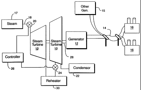
FIGURE 1 is a schematic diagram of a two-section steam
turbine 10 and generator 12 unit that is electrically coupled to a
electrical power grid network 14. The network distributes power
generated by the turbine-unit and other generator units 15 to power
consumers 16. The turbine includes a source of steam 17, such as a
boiler, a steam inlet conduit 18 and a steam inlet valve 20. The steam
exhausts to a condenser 22. Moreover, there may be other parts to the
turbine and the boiler, such as a steam reheater 30 and turbine
intercept valves 24, that are operated by the controller.
A steam turbine controller 26 operates the inlet valve 20 by
adjusting the position of the valve from an open position (which allows
steam to pass through the valve) to a closed position (which blocks the
passage of steam), and to all positions between full closure and full
open. By adjusting the position of the inlet valve the amount of steam
passing through the turbine is controlled, which in turn regulates the
rotational speed of the turbine and its output shaft 28.
9
CA 02352421 2001-07-05
17TU-6018
FIGURE 2 is a schematic and block diagram of a speed
controller 32 for a steam turbine controller, such as the General Electric
(GE) Mark V Steam Turbine Controller. The functions of the controller
are described in terms of a functional logic units and circuits, which can
be implemented as hard-wired circuits, software and/or firmware. The
controller 32 is a portion of an entire steam turbine controller 26. The
other portions of the turbine controller are conventional and are well
known.
The speed control logic unit 34 compares a speed reference set-
point signal 36 (TNHR) with the actual rotational speed 38 (TNH) of the
turbine. The speed set-point is selected for the turbine based on the
load frequency ("rated frequency") applied to the turbine-generator unit
and the operating limits of the unit. Moreover, the set-point is generally
held constant during normal operations of the turbine-generator unit,
even if the frequency demands of the load drift from the rated
frequency. Accordingly, it is not necessary to adjust the set-point to
match load frequency variations, even where such variations range
from 105% to 95% of the rated frequency of the load.
The speed control logic unit 34 filters out minor fluctuations in
the frequency of the load, such as due to jitter, low-amplitude load
variations, and other short-term conditions that should be ignored by
the speed controller. The difference between the actual speed TNH
and the speed reference TNHR is converted by the speed controller 34
into a filtered speed error signal 40 (TNHED). The speed error signal
40 is generated by the speed control logic unit.
A selectable gain 42 is applied to the speed error signal 40
(TNHED). The gain is selectable by the operator of the turbine. The
gain may be a conventional gain 44 used for loads that operate at (or
near) a rated frequency and do not experience extended frequency
CA 02352421 2001-07-05
17TU-6018
shifts. This conventional gain may, for example, impose a 5% speed
regulation (where regulation is the inverse of gain) that fully closes the
steam input valves (and hence shuts down the turbine) if the speed of
the turbine exceeds 105% of rated speed. With 5% speed regulation,
the controller will reduce the steam input valve opening position by
20% for each 1% increase in the turbine speed. A second (slow
change) gain 46 may be selected that is more tolerant of load
frequency variations. An exemplary second gain provides 20% speed
regulation that fully closes the steam input valves (and hence shuts
down the turbine) if the speed of the turbine exceeds 120% of rated
speed. With 20% speed regulation, the controller 32 reduces the
steam input valve opening position by 5%, for each 1% increase in
turbine speed. Accordingly, if the frequency of a load drifts such that
the turbine speed 38 increases to 105% of the turbine rated speed 36,
then the turbine will continue to operate at that speed, if the controller
is operating with 20% speed regulation 46. In contrast, a speed
increase of 105% would cause the controller to shut down the turbine,
if only the 5% speed regulation 44 were being used.
As shown in Figure 2, the controller 32 includes an operator
selection 41 of a variable droop function, where the droop gains are a
5% speed regulation gain (KTNE_G) (46) and a 20% speed regulation
gain (KTNE_GSHORT) (44). These gains are exemplary and may
differ, such is in number of selectable gains and their rate, with different
embodiments of this invention. Moreover the gain (e.g., 20% or 5%),
may be adjustable by the operator or turbine manufacturer may set
these rates. In addition, the 5% speed regulation gain is a "long-term"
rate, in that it is applied by the controller (when selected) to
compensate for slow changes (e.g., long-term) to the frequency of the
load and hence the turbine speed. The 5% speed regulation (when the
20% gain is selected) is also used to compensate the turbine speed for
quick frequency and speed changes. If the turbine begins to quickly
11
CA 02352421 2001-07-05
17TU-6018
accelerate (such as might occur if the load is rejected or otherwise
disconnected from the turbine), then the controller applies the 5%
speed regulation to rapidly close the steam inlet valves and avoid
having the turbine trip on overspeed.
The selected speed regulation rate is applied to a gain unit 48,
e.g., linear multiplier. The gain unit 48 adjusts the speed error signal
40 (TNHED) in proportion to the selected speed regulation gain rate
42. The gain unit 42 generates an uncorrected speed*gain signal 50.
This uncorrected speed*gain signal is further processed depending on
the speed regulation rate (44 or 46) that has been selected by the
operator. In particular, if a short-term rate is selected, e.g., 5% speed
regulation, then a gain selection switch 52 in the controller routes the
uncorrected speed*gain signal 50 via line 54, around a delay unit 56
and through a summation logic unit 58, and out as the corrected
speed*gain signal (TNHEX) 60. When the normal speed regulation
rate 46 is selected (which will occur when the load does not experience
substantial frequency fluctuations), no correction is needed to the
uncorrected speed-gain signal, because that signal is already
sufficiently responsive to compensate for quick accelerations of the
turbine. Accordingly, the summation unit 58 does not adjust the
uncorrected speed*gain signal 50. The summation unit may be
disabled, e.g., turned OFF, when a normal (fast change) gain is
selected.
If the long-term speed gain rate 46, e.g., 5%, is selected, then
the resulting uncorrected speed*gain signal 50 is further adjusted to
compensate for quick accelerations of the turbine speed. Indeed, for
any speed regulation rate that is insufficient to compensate for quick
turbine speed accelerations, a correction may be useful so that the
uncorrected speed*gain signal can be adjusted to properly compensate
for quick accelerations of the turbine. When a long-term speed
12
CA 02352421 2001-07-05
17TU-6018
regulation rate 46 is selected, the gain switch 52 is opened so as to
break delay unit by-pass line 54, and to activate the ramp (delay) unit
56 and associated turbine acceleration compensation unit 62.
To correct the uncorrected speed*gain signal 50 and
compensate for fast turbine accelerations, a rate of speed change
signal 64 is generated and applied to adjust the speed*gain signal.
The uncorrected speed*gain signal 50 is applied to the ramp unit 56
that generates a ramped speed*gain signal 66. The ramp function unit
56 applies a constant rate of change 68 to the speed*gain signal 50
until its output 66 reaches the same value as its input 50. For example,
a sudden and large change in the uncorrected speed*gain signal 50
(which is indicative of a partial load rejection or a sudden addition of a
large load) will be delayed by the ramp function in proportion to the
constant rate of change (K) 68. In contrast, a slowly changing
speed*gain signal 50 will not be substantially delayed. The ramp of the
ramp unit 56 has a slope corresponding to a rate (K) 68 that is selected
by the turbine manufacturer or the power plant engineer. This rate 68
is a ratio of a unit time per unit speed reference signal, such as a 5
seconds for each 1% of the uncorrected speed*gain signal 50.
If the rate (K = 1/5) is 5 seconds per 1% speed*gain signal, then
a 10% step change in speed*gain signal (which corresponds to a 2%
step change in speed error signal (TNHED) and a 5% gain) will be
delayed by 50 seconds (10% * 1/5) until output from the ramp unit 56
as the delayed speed error signal 66. But if this 10% change in
speed*gain signal 50 occurs gradually over a duration of 50 seconds,
then no substantial time delay will occur, and signals 50 and 66 will
have the same value and signal 64 will be equal to zero. A 10% step
change of the uncorrected speed*gain signal 50 leads to a 10%
difference between the uncorrected speed*gain signal input to the
ramp unit and the ramped (output) speed*gain signal. This difference
13
CA 02352421 2001-07-05
17TU-6018
between the speed*gain signal 50 and the delayed speed*gain signal
66 is determined by a difference logic unit 70 that generates a
difference signal 64 (which is representative of a rate of change of the
turbine speed and the acceleration/deceleration of the turbine) that is
input to a second gain logic unit 74. The difference in the current and
delayed signals is representative of the rate of change (e.g.,
acceleration) of the turbine speed.
A large difference signal 64 suggests that a strong response is
needed by the droop governor 32 to support the change in grid
frequency. The fast change gain 44 causes the turbine governor to
react more quickly to correct frequency. The slow change gain 46
would not trigger the governor to react strongly to avoid an overspeed
condition.
An acceleration gain 76 is applied to the difference signal
corresponding to the short-term (or normally used) speed regulation
gain, e.g., 5% rate. That is, the difference signal 64 is based on
speed*gain signals which already reflect the short term gain 46. Thus,
the gain to be applied to the difference signal 64 must be proportional
to the ratio of the short term speed regulation rate and the long term
speed regulation rate. This ratio 78 is determined in a logic unit 76 that
determines the ratio of the short-term and long-term speed gain rates,
e.g. 20% divided by 5% equals a ratio of four (4). The ratio is applied
as a gain rate 78 in the second gain unit 74 that multiplies the ratio with
the current vs. delayed speed*gain difference signal 64, and generates
a speed*gain correction signal 80.
The speed*gain correction signal 80 is summed with the
uncorrected speed*gain signal in the summation unit 58. The
speed*gain correction signal may be larger than the uncorrected
speed*gain signal, especially when the turbine speed is accelerating
14
CA 02352421 2001-07-05
17TU-6018
fast. Indeed, when a turbine is quickly accelerating, the speed*gain
correction signal 80 is intended to override the uncorrected speed*gain
signal 66 so as to cause the droop governor 32 to rapidly close the
steam inlet valves, and thereby prevent the turbine from over-speeding.
The output of the summation unit 60 is a corrected speed*gain
signal (TNHEX). As shown in FIGURE 3, the corrected speed*gain
signal (TNHEX) may be further processed by, for example, a "fixed
speed error deadband" logic unit 82, which establishes a deadband
around rated frequency, and that filters out small speed*gain signals
and generates a filtered corrected speed*gain signal 85. For example,
the deadband logic unit may filter out speed*gain signals that are below
a threshold level, such as below a speed error signal within 0.5% of the
rated speed-set point. This deadband filter may, alternatively, be
incorporated in the speed control unit 34 and applied directly to the
speed error signal (TNHED).
The corrected speed*gain signal, after being processed by the
deadband filter, is summed (added or subtracted) in summation unit 83
with a load reference signal 84. The load reference signal (also
referred to as the load set-point) is used by the turbine operator to
adjust the turbine load.
The summation unit 83 generates a combined turbine speed
(based on the corrected speed*gain signal) and power control (based
on the load reference signal) signal 86 (TPWR). In addition, there are
other functions, such as limiting signals, entering the summation unit
83. This signal 86 is applied by the controller to adjust the steam valve
settings that regulate the flow of steam through the turbine. For
example, by reducing the opening of the input valve 20 the amount of
steam entering the turbine is reduced and the turbine-generator will
produce less power.
CA 02352421 2001-07-05
17TU-6018
While the invention has been described in connection with what
is presently considered to be the most practical and preferred
embodiment, it is to be understood that the invention is not to be limited
to the disclosed embodiment, but on the contrary, is intended to cover
various modifications and equivalent arrangements included within the
spirit and scope of the appended claims.
16