Note: Descriptions are shown in the official language in which they were submitted.
CA 02352642 2004-07-13
BRAKE STRUCTURE OF BAND REEL IN PACKING MACHINE
BACKGROUND OF THE INVENTION
FIELD OF THE INVENTION
The present invention relates to a brake structure of
a band reel in a packing machine.
DESCRIPTION OF THE RELATED ART
In an automatic or semi-automatic banding packing
machine, a band reel 1 having a long band B wound thereupon
is provided in a packing machine body 2 as shown in Fig. 4.
A tip of the band B led from the band reel 1 is fed to the
packing machine body 2 side by the rotating force of a feed
roller (not shown) or the like.
In addition, a brake arm 3 is provided in the vicinity
of the band reel 1 and the band B is fed to the packing
machine body 2 side through a guide roller 3a of the brake
arm 3.
In such a packing machine, in the case in which, in
one packing step, the band is completely fed from the band
reel 1 and is to be then returned and tightened, the
rotation of the band reel 1 should be stopped immediately.
Otherwise, an extra band is loosened so that a slack
portion of the fed band hangs, and twist and entanglement
are caused in the vicinity of the guide roller 3a.
It is conventional to stop the rotation of the band
reel 1 immediately after the band is completely fed, by
pushing a pad against the side surface of the band reel 1
to stop the rotation by means of the pad. It is also known
1
CA 02352642 2004-07-13
to stop the rotation of the band reel 1 by pushing a V-
shaped brake belt 5 shown in Fig. 5, for example, against a
brake pulley during braking, the brake pulley being
attached to the peripheral surface of a reel shaft 4
pivotally supporting the band reel 1.
In the method using the brake pad, however, the force
for stopping the rotation is small and the band reel 1 is
rotated for a while even if a stop operation is started.
In the method using the brake belt 5, moreover, there has
been a problem in that the force for stopping the rotation
is great but the braking is not stabilized if the intrusion
of the V belt is poor.
SUMMARY OF THE INVENTION
In consideration of the above-mentioned circumstances,
it is an object of the present invention to provide a brake
structure of a band reel in a packing machine in which
braking effects can be obtained reliably and responsiveness
is excellent.
In order to achieve the above-mentioned object, the
present
2
CA 02352642 2001-07-06
SF-'756
invention provides a brake structure of a band reel in a packing
machine which is provided on a reel shaft for being rotated
integrally with a band reel,
wherein a brake arm having a coil spring portion provided
on one of ends and a band passing ring portion provided on the
other end is provided on one of ends of the reel shaft and
one of ends on a coil spring side in the brake arm is fastened
to a fixing member such as a device frame,
the coil spring portion receives force in a direction of
an increase in a diameter by force applied from the fed band
to form a clearance between an outer periphery of the reel shaft
and an inner periphery of the coil spring, when the band inserted
through the passing ring portion of the brake arm is sent toward
a packing machine body side, and
a diameter of the coil spring portion is reduced to closely
engage an inner peripheral surface of the coil spring portion
with an outer peripheral surface of the reel shaft, thereby
stopping a rotation of the reel shaft by :frictional force, when
the force for feeding the band is released.
According to the present invention having such a structure,
when the band feeding operation is ended, the rotation of the
band reel can be stopped, and furthermore, the structure can
be simplified.
According to the brake structure of the band reel in the
packing machine in accordance with the present invention, if
3
CA 02352642 2001-07-06
SF-756
the force for leading out the band through the band feeding roller
is released when the band is completely fed from the band reel,
the diameter of the coil spring portion is reduced so that the
rotation of the reel shaft can be stopped. Accordingly, the
slack portion of the band can be prevented from hanging. In
such a structure, moreover, only the coil spring is used.
Therefore, the structure can be simplified and the responsiveness
can also be enhanced.
These objects as well as other objects, features and
advantages of the present invention will become more apparent
to those skilled in the art from the following description with
reference to the accompanying drawings..
BRIEF DESCRIPTION OF THE DRAWINGS
Fig. 1 is a sectional view showing a band reel comprising
a brake structure according to an embodiment of the present
invention,
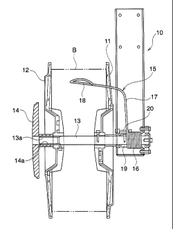
Fig. 2 is a front view showing the band reel,
Fig. 3 is an exploded perspective view showing the brake
structure according to the embodiment,
Fig. 4 is a perspective view showing a packing machine
comprising a conventional band reel, and
Fig. 5 is an exploded perspectives view showing a brake
structure constituted in the conventional band reel.
4
CA 02352642 2004-07-13
DETAINED DESCRIPTION OF THE PREFERRED EMBODIMENT
An embodiment of the present invention will be described
below with reference to the drawings.
Fig. 1 is a view showing a band reel comprising a brake
structure according to the embodiment of the present
invention.
In a band reel 10, a band housing portion for winding a
band B is formed by an inner circular 11, an outer circular
12 and a reel shaft 13. A male screw 13a is formed on the
tip of the reel shaft 13 and a female screw 14a of a nut
handle 14 is screwed into the male screw 13a.
On the other side, a collar 19 is provided at one of the
ends of the reel shaft 13 which protrudes from the inner
circular 11 as also shown in Fig. 3. The collar 19 is
rotated integrally with the reel shaft 13 through a screw
member 20 inserted between the collar 19 and the reel shaft
13. The base end side of a brake arm 15 according to the
present embodiment is provided on the outer peripheral side
of the collar 19.
The brake arm 15 has a coil spring portion 16 provided
on the base end side and a dogleg-shaped arm portion 17
extending on the other end side. An end 16a of the coil
spring portion 16 is fixed unrotatably to a reel bearing case
25 fastened to a device frame or the like. A passing ring
portion 18 for guiding the band B is provided on the tip of
the arm portion
CA 02352642 2001-07-06
SF-756
17. The tip of the band B is caused to pass through the passing
ring portion 18 and is then fed toward the packing machine body
side.
In such a band reel 10, if the tip of the band B is pulled
from the packing machine body side in a direction of an arrow
C as shown in Fig. 2, the band B is led out. While the band
B is led out, that is, band feeding means feeds the band B toward
the packing machine body side, force in the direction of the
arrow C acts on the brake arm 15 in Fig. 3. Accordingly, the
diameter of the coil spring portion 16 is enlarged. Therefore,
when the band B is fed toward the packing machine body side,
a gap between the coil spring portion 16 .and the collar 19 fixed
to the reel shaft 13 is increased. Consequently, the rotation
of the reel shaft 13 cannot be prevented.
On the other hand, when the band B is completely fed, the
force in the direction of the arrow C which pulls the brake arm
15 is released, and conversely, force in .a direction of an arrow
D acts on the coil spring portion 16 by the force for causing
the coil spring portion 16 to return to an original position
as shown in Fig 2 and 3. When the force thus acts in the direction
of the arrow D, the coil spring portion 16 comes into contact
with the peripheral surface of the collar 19 by pressure so that
the collar 19 is brought into an unrotati.on state and the brake
arm 15 is moved from a position shown in a broken line to a position
shown in a solid line in Fig. 2.
6
CA 02352642 2001-07-06
SF-756
Accordingly, if the rotation of the reel shaft 13 is stopped,
the slack portion of the band is not led out any more.
Consequently, the band can be prevented from hanging. In the
case of an automatic machine, the tightening and returning steps
are then started. The returned band is fed into a pool box of
the packing machine body.
While the embodiment of the present invention has been
described above, the present invention is not restricted to the
embodiment.
The present invention can be applied to an automatic
machine and a semi-automatic machine.
Numerousmodificationsand alternative embodiments of the
present invention will be apparent to those skilled in the art
in view of the foregoing description. Accordingly, this
description is to be construed as illustrative only, and is
provided for the purpose of teaching those skilled in the art
the best mode of carrying out the invention. The details of
thestructureand/orfunction maybe variedsubstantiallywithout
departing from the spirit of the invention. and all modifications
which come within the scope of the appended claims are reserved.
7