Note: Descriptions are shown in the official language in which they were submitted.
CA 02352747 2001-05-29
°a
SPECIFICATION
TITLE OF THE INVENTION
Manufacturing Method for Bottle-Shaped Can
TECHNICAL FIELD
The present invention relates to a manufacturing method for a bottle-
shaped can, of which a can body, a shoulder portion and a neck portion are
1o integrally shaped fiom a metallic sheet (or a metal sheet), and, more
particularly, to a method of manufacturing a bottle can with the outer surface
of its body portion or the outer surface of the portion from its body portion
to
its shoulder portion being decorated with a print or the like.
t 5 BACKGROUND ART
As beverage cans for various soft drinks, juice or beer, there are
generally employed the two-piece cans, of which the can body (or side wall
portion) and the can bottom (or end wall portion) are integrally shaped. The
two-piece can of this kind is manufactured by a suitable method such as by
2o drawing and ironing, by drawing/redrawing, or by drawing/redrawing and
stretching a metallic sheet such as an aluminum alloy sheet or a surface-
treated steel sheet.
In such a two-piece can, there are integrally shaped the can bottom
having a domed shape for improving the pressure resistance and the thinned
25 body portion, and the open upper end portion of the body portion side wall
is
necked in to reduce the diameter and is flanged.
-1-
CA 02352747 2001-05-29
Moreover, the two-piece can is filled with a body such as a juice, soft
drinks or beer, and the flanged portion of the open body portion is then
seamed and sealed with an easy open can end having a smaller diameter than
the external diameter of the body portion so that the can is shipped as a
bever age can.
This beverage can is opened by a consumer having purchased it
when the consumer pulls a tab fixed on the easy open can end.
As disclosed in WO 81/01259, on the other hand, there is also
manufactured a bottomed cylindrical can which is shaped to have a thinner
to body wall than a bottom wall by drawing and redrawing (or by bending and
extending at the redrawing time or by stretching) the surface-treated steel
sheet having two sides laminated with a thermoplastic resin film. The can
thus manufactured is necked in and flanged like the aforementioned can so
that it may be used as the beverage can.
As the containers for soft drinks, juices, teas or coffees, on the other
hand, there have been employed in recent years the bi-oizented molded
containers (i.e., the PET bottle) made of a polyethylene terephthalate resin.
Accordingly, the various soft drinks and others contained in the re-sealable
PET bottles are mass-produced and sold by filling the bottles with them and
2o by sealing the bottles with the threaded caps.
These beverage PET bottles have an advantage over the can
containers for the beverages in that they can be repeatedly sealed with the
caps. However, the PET bottles are in considerably lower states than those
of the can containers in the recycling ratio for recovexzng and recycling the
bottles. Therefore, it has been investigated to enhance the conveniences of
the can containers by adding to the re-sealing function to the can containers
-z-
CA 02352747 2001-05-29
having a high recycling ratio.
As the metallic cans which can be re-sealed with the threaded caps,
there are disclosed in Japanese Patent Laid-Open No. 10-509095
(W096/15865) several types of bottle-shaped drawn/ironed cans (i.e., DI cans)
having shapes similar to those of the PET bottles, i.e., the DI cans which
have
threaded neck portions to be screwed with threaded caps.
These DI cans are classified into: the type in which an end sheet to be
seamed on the open upper end of a can body is formed to form a threaded neck
portion integrally; the type in which the threaded neck portion is integrally
1o formed by reducing the diameter of the open upper end side of the can body
stepwise by the neck-in working (i.e., by making the diameter smaller toward
the open end); and the type in which the small diametxzcal neck portion and
the shoulder portion having a slope are foxmed by drawing the drawn bottom
portion side (or the end wall portion) of a cup at multiple steps, in which
the
neck portion is then opened and is curled and threaded, in which the body
portion of the cup is then drawn and ironed into a thin body portion, and in
which a separate bottom end is seamed and fixed on the open end of the body
portion on the side opposed to the neck portion.
In the above-specified Laid-Open, moreover, there are disclosed not
only the structures of the bottle-shaped cans of the individual types but also
their shaping (or forming) methods.
According to the disclosure of Japanese Patent Laid-Open No. 58-
47520, on the other hand, at the time of drawing the can body, the bottom
portion is drawn into a convex stepped shape, and this convex stepped shape
is redrawn at an ironing time, to form a stepped convex portion having a small
diametrical cylinclizcal neck portion and a raised shoulder portion. This neck
-:3-
CA 02352747 2001-05-29
c r
portion is threaded and is sealed with the threaded cap. After this DI can
was filled with a beverage from the end opening of the body portion, this end
opening is sealed by seaming and fixing the can end.
In Japanese Patent Laid-Open No. 64-47520, moreover, the following
concept is disclosed. By pressing (or drawing) the bottom side of the DI can
shaped by the drawing/ironing treatment, there are shaped a small
diametrical cylindrical neck portion and a frustoconical shoulder portion.
The leading end portion of the neck portion is trimmed, and the lubricant
having stuck the inner and outer surfaces of the can is degreased/rinsed.
l0 The inner and outer ~sux~faces of the can are conversion coated and dried.
After this, a coating for the inner surface is sprayed on the inner surface of
the
can. After the coating is dried, a print is applied to the outer surface of
the
body portion of the can. After this printing ink is dxled, a can end is seamed
and fixed on the open end of the body portion. After this, a threaded
cylindxzcal member of a resin is fitted on the neck portion, or this neck
portion
is screw-cut.
Of the aforementioned bottle-shaped cans which can be sealed again
with the threaded cap, the can of the type in which the threaded neck portion
is formed integrally with the end sheet is formed at its body into the DI can
or
2o a bottomed can such as the DTRD can (Drawn Thin Redrawn) having been
drawn and bent/extended (or stretched) or the can having been drawn and
bent/extended (or stretched) and ironed. The can body is filled with a content
such as a beverage, and the open end portion of the can body is seamed/fixed
and sealed with the end sheet having the threaded neck portion formed
integrally therewith.
According to the bottle-shaped can of this type, therefore, the can
-4-
CA 02352747 2001-05-29
body has a shape substantially identical to that of the existing general can,
and enjoys an advantage that few changes are required in the filling
facilities
to suppress the cost for the facilities.
In the bottle-shaped can of this type, however, the end sheet seaming
portion is located in the upper portion of the can to raise problems that dust
is
liable to accumulate in the concave portion inside of the seamed portion, and
that the seamed portion itself protrudes to deteriorate the appearance.
In the bottle-shaped can of the type in which the neck portion is
formed not at the end sheet but integrally at the upper end portion of the can
l0 body, on the other hand, the upper end portion is stretched thin and worked
hard by a similar working as the can body is drawn and ironed or bent and
extended. Considering the later step of working the neck portion, therefore,
the upper end portion of the can body is worked so relatively thick as to make
the extension of the matexzal less than the lower portion (or as to reduce the
work hardening extent).
Since the neck portion has a considerably smaller diameter than that
of the can body (or the body portion of the can), however, a diameter
reduction
ratio for forming the neck portion is so large as to make it necessary to make
a
diameter reduction work many times.
2o When the number of the diameter reduction work is reduced by
enlarging one drawing rate, on the other hand, the can body is wrinkled or
cracked at its upper end portion.
In order that a small cap may be used to lower the cost for the
material and that the consumer may drink the beverage in the can directly
27 from the neck portion without spilling the content, it is desired to reduce
the
diameter of the neck portion more than the external diameter of the can body.
_,5_
CA 02352747 2001-05-29
In order to satisfy these desires, it is necessary to make the reduction
ratio higher for forming the neck portion by drawing the open upper end of
the can body, and this necessity requires several tens of neck-in steps.
For example, the can to be relatively frequently used as the body can
for beer has a body diameter of about 66 mm ( the so-called "211 diameter"),
and twenty to thirty necking steps are required if the neck portion of such
can
is to be necked in to a diameter of about 28 mm.
Thus, in the bottle-shaped can having the neck portion formed by
reducing the diameter of open upper end of the can body, a number of necking
machines are required to raise the cost for the facilities, and the increase
in
the number of working steps makes it frequent to damage or deform the can
thereby to lower the quality of the can.
In the bottle-shaped can of the type in which the shoulder portion
and the neck portion are formed by working the can bottom, on the contrary,
the can bottom portion or the portion to be formed in a portion of the
shoulder
portion and the neck portion is hardly affected by the working to form the can
so that the working is applied to the portion having no work hardening and
having a thickness substantially equal to that of the original metallic sheet.
When the can bottom is to be drawn, moreover, the diameter of the neck
portion can be reduced while being unwrinkled.
As compared with the case in which the neck portion is formed by
necking in the upper portion of the aforementioned can body, therefore, one
drawing rate can be increased to reduce the diameter more by one step
thereby to drastically reduce the number of steps for forming the neck
portion.
On the other hand, the bottle-shaped can of the type in which the
bottom side is worked to shape the shoulder portion and the neck portion has
-6-
CA 02352747 2001-05-29
c
neither a seamed portion at its upper portion nor a recess liable to trap dust
while the can is displayed at a store fiont, so that it has an excellent
appearance.
Here in the aforementioned bottle-shaped can which has its neck
portion, shoulder portion and body portion shaped integrally so that it can be
re-sealed with the threaded cap, a protecting coating film is applied to the
metallic surface of the can so as to protect the content and retain the
corrosion
resistance. If the metallic sheet is then pre-coated with the protecting
coating film, this film is damaged when the can is ironed. It is, therefore,
0 disclosed in Japanese -Patent Laid-Open No. 10-509095 that the protecting
coating film is formed after the ironing treatment.
In Japanese Patent Laid-Open No. 58-47520, on the other hand, it is
not disclosed in the least when the protecting coating film is applied, when
the
small diametrical cylindrical portion is cut and opened or when the same is
t5 threaded.
According to the disclosure of Japanese Patent Laid-Open No. 64-
47520, on the other hand, a bottomed cylindrical can body having a thin body
portion is shaped by the drawing treatment and the ironing treatment. After
this, the can body is drawn at its bottom portion to shape a small diametrical
20 cylindrical portion and a frustoconical shoulder portion. After the upper
end
portion of the small diametrical cylindrical portion is cut and removed, a
degreasing treatment is perfoxmed to rinse the inner and outer surfaces of the
can body, and this body is dxled. A protective coating is then applied to the
inner surface of the can body and is dried. After this, a print is applied to
the
25 outer surface of the can body.
According to our experiences, however, it is sexzously difficult to
-7_
CA 02352747 2001-05-29
4 r
apply a protective coating of a uniform thickness to the metal surface of a
can
(before the bottom end is fixed) having the curled portion or the threaded
portion formed at the small diametxzcal neck portion and to dry and set the
coating to a proper state.
According to the shaping method utilizing the ordinary DI can
manufactuxzng method, on the other hand, a cup of a metallic sheet having a
surface laminated with no thermoplastic resin is redrawn and ironed while
spraying much water lubricant to the cup. Therefore, much degreasing
liquid, conversion coating liquid and rinsing water is required for the
rinsing
treatment. This makes it necessary to employ large-sized rinsing facilities
and the much lubxzcant, degreasing liquid, conversion coating liquid and rinse
water. This necessity is a factor to raise the can manufacturing cost
drastically.
In order to simplify the degreasing treatment after the can body is
shaped, therefore, we have adopted the following method. A thermoplastic
resin film layer performing a function as the lubricant is formed in advance
as
the protective film on the metallic sheet for the material of the can, and a
small amount of lubxzcant is applied to the protective film. The coated
metallic sheet thus having the protective film is shaped into an integral
structure of a thin body portion, a shoulder portion and a neck portion. After
this, the neck portion is shaped to have a curled portion and a threaded
portion.
The bottle-shaped can thus manufactured fiom the coated metallic
sheet need not be coated later for protecting it. If a high-temperature
volatile
(or sublimable) lubricant is employed, the degreasing treatment can be simply
effected by a heating treatment. Even in the case of a non-high-temperature
.g_
CA 02352747 2001-05-29
volatile lubricant, on the other hand, the degreasing treatment can be
effected
with a small amount of zznse water.
Where a print of letters or decorative patterns is to be applied to the
body portion of a container, the PET bottle can not be printed directly on the
entire circumference of the bottle body, or a printed resin film cannot be
fusion-bonded as a matter of fact, because its body portion is not circular,
corrugated or extremely thin. Therefore, the print is applied by shrink-
packaging the bottle body with a printed heat-shrinkable film.
In the metallic bottle-shaped can of the type in which the threaded
neck portion, the shoulder portion and the body portion are integrally shaped
and in which the bottom end is seamed and fixed on the lower end portion of
the body pot~tion, an opening of the same external diameter as that of the
body
portion is kept till the neck-in step before the bottom end is fixed. It is,
therefore, possible to pz~nt the can body directly as in the two-piece can of
the
prior art and to thermally adhere (or fusion-bond) the printed resin film.
Thus, an appearance different from that of the PET bottle can be obtained to
differentiate the products.
Even where the body portion, the shoulder portion and the neck
portion of the metallic bottle-shaped can are to be integrally shaped fiom the
coated metallic sheet having the protective film, however, this protective
film
may be damaged by the friction at the shaping time by the drawing or ironing
treatment, unless the lubricant is applied in advance to the sux~'ace of the
coated metallic sheet. Where the decorative px~.nt is to be applied to the
body
of the bottle-shaped can, on the other hand, it is made impossible fiom the
view points of the repellency of the ink or adhesiveness to directly pxznt the
outer surface of the can in the state having the lubxzcant or to fusion-
bonding
-9-
CA 02352747 2004-06-22
the printed resin film to the same. Therefore, it is a problem what stage
(time) of the manufacture process is most suitable to the printing (or the
fusion-bonding of the printed resin film) .
In the aforementioned Japanese Patent Laid-Open No. 58-47520,
there is no disclosure at what point of time the decorative print should be
applied .
In the aforementioned Japanese Patent Laid-Open No. 64-62233, on
the other hand, the following is disclosed. After the bottomed cylindrical can
body is drawn at its bottom side to shape the small diametrical cylindrical
portion and the frustoconical shoulder portion, the upper end portion of the
small diametrical cylindrical portion is cut and removed. After this, the can
body is rinsed at its inner and outer surfaces and is dried. After this, the
coating is sprayed on the inner surface of the can body. After the coating is
dried, the coating and the print are applied to the outer surface of the can
body.
According to the manufacturing method for the bottle-shaped can
body, as disclosed in Japanese Patent Laid-Open No. 64-62233, the coating
is sprayed on the inner surface of the cylindrical can body after this can
body is drawn at its bottom portion to form the small diametrical cylindrical
portion and the frustoconical shoulder portion.
It is, however, not easy to apply the protective coating of a uniform
thickness to a body having portions of different diameters combined, such as
the inner surface of the bottle-shaped can body after the cylindrical body
portion, the frustoconical shouldex portion and the small diametrical
cylindrical portion are formed.
For coating the inner surface of an axticle having such complicated
- to -
CA 02352747 2004-06-22
shape, more specifically, the spray coating is commonly used, as disclosed in
Japanese Patent Laid-Open No. 64-62233. However, the coating film is
liable for the spray coating to become thick at a small diametrical portion
but thin at a large diametrical portion. Therefore, a coating consumption is
excessively high if a sufficient application is to be retained for the thin
portion, and a coating film thickness for retaining a sufficient corrosion
resistance cannot be obtained if the coating consumption is limited.
Where the coating film thickness on the inner surface of the bottle
shaped can is seriously different at portions, on the other hand, the drying
l0 degree disperses when the coated film is dried/baked. Therefore, sufficient
corrosion resistance and adhesion may not be able to be obtained to make the
drying/baking works di~cult.
In the bottle-shaped can body manufacturing method disclosed in
Japanese Patent Laid-Open No. 64-62233, moreover, the can body is printed
on its outer surface after the small diametrical cylindrical portion for the
threaded neck portion is cut/removed at its upper end portion (or its leading
end portion). If, in this case, there is diverted the dry offset printer which
is
employed for printing the ordinary two-piece can (e.g., the DI can or the
deeply drawn can), this diversion is impossible unless a drastic modification
is made. This raises a problem that the cost for the facilities is raised.
In Japanese Patent Laid-Open No. 10-509095, there is disclosed the
bottle-shaped can in which the body portion, the shoulder portion and the
small diametrical cylindrical portion are integrally shaped. The cup, as
adapted by the drawing treatment, is shaped to form the small diametrical
cylindrical portion and the shoulder portion. After this, the small
diametrical cylindrical portion is cut and opened at its leading end portion.
-11-
CA 02352747 2001-05-29
After this, the small diametrical cylindrical portion is curled and threaded
at
its leading end portion. Moreover, the cup is redrawn and ironed to elongate
the can body wall and is coated for the protection. Therefore, the problem of
the bottle-shaped can disclosed in Japanese Patent Laid-Open No. 64-62233
is just as the same as that of the bottle-shaped can of the aforementioned
type,
as disclosed in Japanese Patent Laid-Open No. 10-509095.
In the prior art in which the two-piece can is directly printed at its
cylindrical body portion or in which the printed resin film is fusion-bonded
to
the body portion of the two-piece can, as disclosed in Japanese Patent Laid-
0 Open No. 9-295639 (corresponding to EP-A2-0,808,706), the transfer means
employed for feeding/discharging the cans to the mandrels or the like of a
printing apparatus or a printed resin film applying apparatus is exemplified
by the transfer means utilizing the vacuum and compressed air injection
mechanism (as disclosed in Japanese Patent Laid-Open No. 48-58905
(corresponding to USP No. 3,766,851), Japanese Patent Laid-Open No. 52-
41083 (corresponding to USP No. 4,048,917), USP No. 4,092,949, Japanese
Patent Laid-Open No. 54-92810, Japanese Patent Laid-Open No. 57-170758
or Japanese Patent Laid-Open No. 57-178754).
For the printing of the bottle-shaped can body disclosed in Japanese
2o Patent Laid-Open No. 64-62233 or Japanese Patent Laid-Open No. 10-509095,
the tr ansfer means utilizing the vacuum and compressed air injection
mechanism cannot be used at the pxznting time when the bottle-shaped can
body is to be fed to and discharged from the mandrels of the printing
apparatus, because an opening is present at the leading end portion of the
small diametxzcal cylindxzcal portion in addition to the opening at the
leading
end of the body portion.
-12-
CA 02352747 2004-06-22
It is, therefore, necessary to add a mechanism for grasping and
pushing the bottle-shaped can body reliably on the mandrels of the printing
apparatus and a mechanism for grasping and removing the bottle-shaped can
body reliably from the mandrels. As a result, those modifications to the
printing apparatus raise a problem that high expenses are required for the
facilities to raise the cost considerably for manufacturing the can.
Since the bottle-shaped can body is grasped for its transfer, on the
other hand, there arises another problem that the transfer rate is reduced to
have a low printing speed.
1o A main object of the invention is to provide a method for
manufacturing such a re-sealably threaded bottle-shaped can at a low cost
that a small diametrical neck portion, a shoulder portion and a large
diametrical body portion are integrally molded from a metallic sheet (or a
metal sheet), that a homogeneous protective film is applied to the inner
surface of this portion, and that a decoration paint is applied at least to
the
body portion.
A more specific object of the invention is to provide a manufacturing
method for a re-sealably threaded bottle-shaped can, in which no protective
coating is needed on the inner surface of the can after manufactured and in
2o which the decoration print can be applied to the body portion without any
drastic modification on the decorating apparatus of the prior art for the
outer
surface of the body portion of the two-piece can.
SUMMARY OF THE INVENTION
In order to achieve the above-specified objects, according to the
invention, there is provided a manufacturing method for a bottle-shaped can
- 13-
CA 02352747 2001-05-29
in which a small diametizcal neck portion, a shoulder portion having a sloped
face and a large diametizcal body portion are integrally shaped, in which a
decoration print is applied at least to the outer surface of the body portion
and
in which a bottom end is fixed on the lower end portion of the body portion,
comprising: a cup shaping step of preparing a covered metallic sheet, by
forming thermoplastic resin coating films on the two surfaces of a metallic
sheet and by applying a lubricant to the thermoplastic resin coating films,
and
punching out the covered metallic sheet to form a cup shape; a can shaping
step of shaping the shaped cup further into a bottomed cylindrical can which
0 is reduced at diameter of the body and thinned at its body portion; a
diametrical small cylindxzcal portion shaping step of shaping the bottom
portion of the bottomed cylindrical can and the body portion in the vicinity
of
the bottom portion into the shoulder portion and an unopened small
diametrical cylinchzcal portion; an opening step of cutting and opening the
~5 leading end portion of the small diametrical cylindrical portion; a neck
portion
shaping step of shaping the neck portion by threading the outer circumference
of the opened small diametrical cylindrical portion; a lubilcant removing step
of removing the lubizcant fiom the outer surface of the bottomed cylindrical
can, between the step of shaping the bottomed cylindrical can having the
20 thinned body portion and the step of cutting and opening the leading end
portion of the small diametxzcal cylindrical portion; and a decorating step of
decoratively panting the outer sux~'ace of the body portion of the bottomed
cylindrical can cleared of the lubricant, between the step of shaping the
bottomed cylindxzcal can having the thinned body portion and the step of
25 cutting and opening the leading end portion of the small diametrical
cylindxzcal portion.
-14-
CA 02352747 2001-05-29
According to the bottle-shaped can manufacturing method of the
invention, therefore, the metallic sheet still in the flat state before shaped
is
laminated in advance on its two surfaces with the thermoplastic resin so that
the thermoplastic resin as the protective film can be applied in the uniform
thickness to the metallic sheet surfaces. Since the small diametrical
cylindxzcal portion (or the neck portion), the shoulder portion and the body
portion are integrally shaped from the coated metallic sheet (i.e., the
metallic
sheet with the protective film) prepared by applying the lubricant to the
thermoplastic resin layer, on the other hand, the protective film for
protecting
the metallic sheet of the can is not damaged at the step of shaping the small
diametrical cylindxzcal portion, the shoulder portion and the body portion
integrally. Since the protective film is formed of the thermoplastic resin
layer, moreover, this thermoplastic resin layer not only functions a lubricant
when the small diametxzcal cylindrical portion (or the neck portion) is bent
or
W threaded after the lubricant is removed but also is extended or bent
following
the extension or bend of the metallic surface, so that protective film does
not
peel off.
In short, no protective covering need be applied to the inner surface
and the outer surface of the shaped can. As a result, there is raised neither
such problems in the coating workability or in the irregularity of the
thickness
of the protective film as might otherwise occur where the coating is sprayed
to
the inner surface of the can after made.
According to the bottle-shaped can manufacturing method of the
invention, on the other hand, the step of removing the lubxzcant from the body
2~ portion of the can and the step of pxlnting the decoration are performed
after
the bottomed cylindrical can having the thinned body portion is shaped and
-15-
CA 02352747 2001-05-29
before the small diametxzcal cylindxzcal portion is cut and opened at its
leading end portion. By employing the transfer means according to the
vacuum or compressed air injection mechanism which the printing apparatus
or the printed film resin film adhering appratus of the prior art is equipped
with, therefore, the bottle-shaped can can be fed to and discharged from the
mandrels of the printing apparatus or the printed resin film adhering
apparatus. Therefore, the decoration step can be effected at a high speed.
In the bottle-shaped can manufacturing method of the invention, on
the other hand, the step of printing the body portion of the can or adhering
the
x0 printed resin film is performed after the lubxzcant removing step so that
the
pxzrxting operation or the printed resin film adhex~ng operation can be
performed in a satisfactory state.
In the method of the invention, on the other hand, the lubricant
removing step and the decoration step may be executed between the small
diametxzcal cylindrical portion shaping step and the opening step.
In the bottle-shaped can manufacturing method of the invention,
therefore, the shoulder portion and the small diametx2cal cylindrical portion
are shaped before the lubricant is removed, so that these shaping steps are
performed with the lubricant being left on the thermoplastic resin layer. It
is,
therefore, possible to perform the numerous steps of shaping the small
diametxzcal cylindrical portion and the shoulder portion while preventing the
thermoplastic resin film from being damaged.
In the bottle-shaped can manufacturing method of the invention, on
the other hand, the bottle-shaped can at the instant when it is fitted (or
crowned) on the mandrels of the pxznting apparatus or the pxzxxted resin film
adhexzng apparatus has a small diametrical cylindxzcal portion formed on its
- 16-
CA 02352747 2001-05-29
bottom portion. By the modifications that the mandrel is partially matched
to the shape of the shoulder portion of the can and that the inner surface of
the vacuum pad for sucking the can is partially matched to the shape of the
shoulder portion shape of the can, however, the vacuum and compressed air
injection mechanism can be employed when the can is to be fed to and
discharged from the mandrel. Therefore, it is possible to suppress the cost
for the modifications.
In the method of the invention, still moreover, the lubricant removing
step and the decoration step may be executed between the can shaping step
to and the small diametrical cylindrical portion shaping step, and a lubricant
applying step of applying a lubricant at least to the outer surface of the
bottomed cylindrical can may be executed immediately after the decoration
step.
In the bottle-shaped can manufacturing method of the invention,
therefore, at the stage where the bottomed cylindrical can is shaped, the
lubxzcant is removed, and the decoration print is applied to the outer surface
of the cylindrical body portion. Therefore, the printing apparatus or the
printed resin film adhering apparatus, as has been employed for printing the
body portion of the two-piece can, can be employed without any modification.
In the bottle-shaped can manufacturing method of the invention, on
the other hand, after the body portion is printed, the lubricant is applied to
the bottle-shaped can, and the can bottom portion including the vicinity of
the
bottom portion of the printed body portion is shaped into the shoulder portion
and the small diametrical cylindxzcal portion. It is, therefore, possible to
manufacture the can in which the decoration print is applied at least to such
a
portion of the shoulder poWion of the bottle-shaped can as can not be
-li-
CA 02352747 2004-06-22
decoratively printed by the ordinary printing means.
Still moreover, the small diametrical cylindrical portion shaping step
of the method of the invention may be executed: such that the bottomed
cylindrical can is preliminarily molded at its bottom corner portion into a
curved shoulder face having an arcuate longitudinal section and is then
drawn at its bottom portion into a bottomed cylindrical portion of a smaller
diameter than that of the body portion while the curved shoulder face of the
bottom corner portion being unwrinkled by a pair of unwrinkling pusher and
drawing dies having curved faces to contact closely with the curved shoulder
face; such that after this, an unwrinkling pusher, which is provided at its
leading end portion with a tapered face having a substantially straight
longitudinal section approximating a tangential line drawn to an arcuate
longitudinal section of an imaginary extension of curvature of the curved
shoulder face, a redrawing dies, which is positioned at a portion to face at
least the unwrinkling pusher and which is provided at its leading end portion
with a tapered face having a substantially straight longitudinal section
approximating a tangential line drawn to an arcuate longitudinal section of an
imaginary extension of curvature of the curved shoulder face, and a redrawing
punch are used to perform one or more redrawing treatments for reducing the
diameter of the bottomed cylindrical portion, while the bottom corner portion
of the bottomed cylindrical portion of the small diameter formed by the
drawing treatment being unwrinkled, thereby to shape the bottomed
cylindrical portion of the small diameter into a small diametrical cylindrical
portion of substantially the same diameter as that of the neck portion; and
such that after this, one or two or more continuing tapered faces formed
between the small diametrical cylindrical portion and the curved shoulder face
are extended and re-shaped
-18-
CA 02352747 2005-12-13
into a smooth curved face leading to the curved shoulder face by a pair of re-
shaping tools having a surface shape of a virtual curved face extending from
the curved shoulder face, to form the shoulder portion into a domed curved
face.
According to the bottle-shaped can manufacturing method of the
invention, therefore, it is possible to manufacture the bottle-shaped can
which
is provided between the small diametrical cylindrical neck portion and the
cylindrical body portion with the shoulder portion having a domed curved face.
Alternatively, the small diametrical cylindrical portion
manufacturing step of the method of the invention may be executed: such that
at the small diametrical cylindrical portion shaping step, the bottomed
cylindrical can is preliminarily molded at its bottom corner portion into a
curved shoulder face of an arcuate longitudinal section and is then drawn at
its bottom portion into a bottomed cylindrical portion of a smaller diameter
than that of the body portion while the curved shoulder face of the bottom
corner portion being unwrinkled by a pair of unwrinkling pusher and
drawing dies having curved faces to contact closely with the curved shoulder
face; such that after this, an unwrinkling pusher, which is provided at its
leading end portion with a sloped face having a substantially straight
longitudinal section approximating a tangential line drawn to an arcuate
longitudinal section of an imaginary extension of curvature of the curved
shoulder face, a redrawing dies, which is positioned at a portion to face at
least the pusher, which is provided at its leading end portion with a sloped
face having a substantially straight longitudinal section approximating a
tangential line drawn to an arcuate longitudinal section of an imaginary
extension of curvature of the
-19-
CA 02352747 2001-05-29
curved shoulder face and which is provided at its portion on the leading end
side fiom the sloped face with a bulging face having an arcuate longitudinal
section, and a redrawing punch are used to perform one or more redrawing
treatments for reducing the diameter of the bottomed cylindrical portion,
while the bottom corner portion of the bottomed cylindxzcal portion of the
small diameter formed by the dr awing treatment being unwrinkled, thereby
to shape the bottomed cylindrical portion of the small diameter into a
radially
small cylindxzcal portion of substantially the same diameter as that of the
neck portion; and such that after this, one or two or more tapered faces
formed
x0 between the small diametxzcal cylindrical portion and the curved shoulder
face are extended and re-shaped into a smooth sloped face leading to the
curved shoulder face by a pair of re-shaping tools having a surface shape of a
straight longitudinal section approximating a tangential line drawn to a
virtual curved face extending fiom the curved shoulder face, to foxzrx the
shoulder portion shape into a smooth curved face of a straight longitudinal
section leading to the curved shoulder face.
According to the bottle-shaped can manufacturing method of the
invention, therefore, it is possible to manufacture the can which is
decoratively printed at least on its body portion and which has the shoulder
portion having the smooth curved face of the straight longitudinal section
mainly.
On the other hand, the neck portion shaping step may be to curl the
leading end portion of the small diametrical cylindrical portion opened, to
form a curled portion and to thread the cylindrical portion below the leading
end portion directly to form a thread.
According to the bottle-shaped can manufacturing method of the
_Zp_
CA 02352747 2001-05-29
invention, therefore, the upper end of the neck portion is curled to provide a
soft touch for the lips of a consumer when the consumer drinks the content
directly from the neck portion of the bottle-shaped can. On the other hand,
the neck portion is directly threaded to make the cost lower than the
structure
in which another threaded part is employed.
Alternatively, the neck portion shaping step may be to fit a
cylindrical member of a resin threaded in advance, on the small diametrical
cylindrical portion and to bend the leading end portion of the small
diametrical cylindrical portion opened, outward to bring the same into
to engagement with the cylindrical member of the resin.
According to the bottle-shaped can manufacturing method of the
invention, therefore, the step of forming the threaded neck portion is
simplified.
i5 BRIEF DESCRIPTION OF DRAWINGS
Fig. 1 is a partially sectional side elevation showing one example of a
bottle-shaped can manufactured by a method of the invention.
Fig. 2 is a process diagram for explaining a manufacture process for
manufacturing the bottle-shaped can shown in Fig. 1.
20 Fig. 3 is an explanatory diagram showing a shaped state of a neck
portion and a shaped state of a shoulder portion at a top doming step of the
process shown in Fig. 2.
Fig. 4 is a conceptional diagram showing a mechanism for
transferring a can to a mandrel of a printing/coating apparatus in a
25 printing/coating step of the process shown in Fig. 2.
Fig. 5 is a conceptional diagram showing a mechanism for receiving
-21-
CA 02352747 2004-06-22
the can from the mandrel.
Fig. 6 is a partially sectional side elevation showing one example of a
printed bottle-shaped can manufactured by another method according to the
invention.
Fig. 7 is a process diagram for explaining a manufacture process for
manufacturing the bottle-shaped can shown in Fig. 6.
Fig. 8 is an explanatory diagram showing a printed region of a can at
the individual stages of the top doming step of the bottle-shaped can.
Fig. 9 is a partially sectional side elevation showing the neck portion
to of the bottle-shaped can manufactured by the method of the invention.
Fig. 10 is a longitudinal section showing a portion of an example in
which a cylindrical member of a resin having a threaded portion and an
annular bulge for fixing the tamper evidence band of a tamper evidence cap is
fixed on the neck portion by working a smaller-diameter cylindrical portion of
a bottle-shaped can.
Fig. 11 is a partially sectional view showing another example of the
bottle-shaped can manufactured by the method of the invention.
Fig. 12 is an explanatory view showing a shaped state of a neck
portion and a shaped state of a shoulder portion sequentially at a top doming
2o step in the process for manufacturing the bottle-shaped can shown in Fig.
11.,
in order.
DETAILED DESCRIPTION OF THE INVENTION
A bottle-shaped can manufacturing method of the invention will be
described in detail in connection with its specific embodiments.
Fig. 1 shows one example of the bottle-shaped can which is
-22-
CA 02352747 2001-05-29
manufactured by the method of the invention. A bottle-shaped can 1, as
shown, in which a smaller diametrical cylindrical neck portion 4 is formed
integrally upward from a larger diametrical cylindrical can body 2 through a
domed shoulder portion 3 having an arcuate longitudinal section, is sealed up
at the lower end opening of the can body 2 by seaming and fixing a bottom end
5 thereon. On the outer sunace of the can body 2, moreover, there is either
directly printed a decoration 6 of desired letters or patterns or adhered a
printed resin film so that the printed area (or the decoration area) may fall
on
a hatched cylindrical portion.
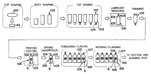
to Fig. 2 schematically shows a process for manufacturing the bottle-
shaped can shown in Fig. 1. In the shown method, the used mateizal is a
covered metallic sheet which is prepared by forming a thermoplastic resin
covering layer in an amoyhous state on the two sides of a metallic sheet and
by applying a high-temperature volatile lubricant to the two sides. At a first
~5 cup shaping step, a blank 100, as punched out in a disc shape from the
covered metallic sheet, is drawn to shape a cup 101. At a next body shaping
step, the cup 101 is redrawn at least one time to shape a bottomed cylindrical
can 102 thinned to have a small diametrical body.
Next, at a top doming step, the bottomed cylindrical can 102 is drawn
20 several times at its bottom portion to shape a shoulder portion 103 and an
unopened neck poWion 104. At a lubxzcant removing step, moreover, the can
102 is heated to a high temperature to remove the lubxzcant at least from the
outer surface of a can lOG which has its neck portion unopened but a body
portion 105 opened at its lower end. At a trimming step, moreover, the body
25 portion 105 is trimmed at its opened end side opposed to the neck portion,
to
set the can 106 to a predetermined length, and the can 106 is transferred to a
. Z;3 .
CA 02352747 2001-05-29
printing/coating step.
At this printing/coating step, the desired decoration 6 is printed on
the body portion 105 of the can 106 having the body portion 105, the shoulder
portion 103 and the unopened neck portion 104 shaped integrally and having
the open lower end, and the thermosetting resin is applied as a clear top
coating layer for protecting the printed ink layer, to the decoration 6. Here,
this top coating layer may be an ultraviolet cured resin.
At a subsequent drying step, the printed ink layer of the decoration 6
and the top coating layer formed over the former are sufficiently dried, and
1o the thermoplastic resin covering layer below the pxzxxted ink layer is made
amorphous. After this, at a threading/curling step, the leading closed portion
of the unopened neck portion 104 is trimmed to open the neck portion 104,
and this opened end portion is curled while being widened outward, to form
an annular curled portion. Moreover, the cylindrical circumferential wall
17 forming the neck portion 104 is threaded at 107 for fastening the cap is
beaded below the thread 107.
Then, at a necking/flanging step, an open lower end portion 108 on
the other side of the neck portion 104 is sequentially necked-in and flanged.
At a not-shown bottom end seaming step, moreover, a bottom end or a
20 separate member made of a metallic sheet is integrally fixed on a flange
formed on the open lower end portion of the body portion by a double seaming
method using a seamer (or a can end seaming machine). Thus, there is
completed the bottle-shaped can 1, as shown in Fig. 1.
Here will be described in more detail the method according to the
2~ invention for manufacturing the bottle-shaped can thus far described. The
raw matexlal or the metallic sheet is prepared to have a thickness of 0.1 to
0.4
-24-
CA 02352747 2001-05-29
mm by laminating a thermoplastic resin film of polyester resin or
polypropylene resin on the two sides of an aluminum alloy sheet. More
specifically, the metallic sheet employed is prepared by laminating a mixed
resin film containing a polybutylene terephthalate resin (PBT) and a
polyethylene terephthalate resin (PET) (PBT : PET = 60 : 40) with a thickness
of 20 ,u m on the inner side and a thickness of 20 ,u, m on the outer side of
an aluminum alloy sheet 3004H191 defined in the Japanese Industrial
Standards (JIS) and having a thickness of 0.315 mm.
Here, the method for laminating the thermoplastic resin film on the
1o metallic sheet is exemplified not only by the method for thermally adhering
the thermoplastic resin film filmed in advance, directly to the metal sux~'ace
of
the metallic sheet but also by extruding thermally adhering the melting
thermoplastic resin film through a T-dies attached to an extruder, onto the
metal surface of the metallic sheet preheated or a method for thermally
adhering a thermoplastic resin film to the metal sunace of the metallic sheet
through an adhesive primer layer, a setting type adhesive layer or an
excellently thermally adhesive thermoplastic resin layer. At this laminating
step, in order to improve the workability and adhesiveness, it is preferable
that the thermally adhered thermoplastic resin film is once melted and then
quenched into an amorphous state by passing it through water, for example.
To the metallic sheet having the thermoplastic resin film layers
formed on its two sides, there is applied as the lubricant one kind or two or
more kinds of normal butyl stearate, fluid para~n, petrolatum, polyethylene
wax, food oil, hydrogen-added food oil, palm oil, synthetic para~n or dioctyl
sebacate. At the cup shaping step, the blank for each can is punched fiom
the covered metallic sheet to which that lubricant has been applied. This
CA 02352747 2004-06-22
blank is drawn into the cup shape. For example, the blank, as punched into
a disc having a diameter of 170 mm, is drawn into a cup shape having a
height of 48.3 mm and an external diameter of 100 mm.
At the subsequent body shaping step, the shaped cup is further
redrawn two times. The shaped cup is bent/extended (or stretched) at the
first redrawing step and is ironed at the second redrawing step by coupling a
redrawing dies and an ironing dies. Thus, there is shaped a bottomed
cylindrical can which has a smaller diameter but a larger height than the cup
and which has a thinned body portion. Together with or after this shaping
step, the bottomed cylindrical can is preformed at its bottom corner portion
(i.e., the bottom portion and the body portion near the bottom portion) into a
curved shoulder face (i.e., a curved shoulder face to form a portion of the
shoulder) having an arcuate longitudinal section. The portion of this curved
face corresponds to the shoulder portion 3 shown on the lefthand upper
portion of Fig. 3. For example, a cup having a height of 48.3 mm and an
external diameter of 100 mm is shaped into the bottomed cylindrical can
having a height of 171.5 mm and an external diameter of 65.9 mm.
In Fig. 3, there is shown the top doming step of forming a top dome of
the can 102 which has been preformed at its bottom corner portion into the
curved shoulder face. For conveniences of explanation, here is arranged the
can 102 with its bottom side taking an upper position. First of all, the
preformed can bottom corner portion is unwrinkled with an unwrinkling tool
(including a drawing dies 111 and an unwrinkling pusher 110), which has a
curved face to come into close contact with the curved shoulder face of the
portion corresponding to the shoulder portion 3. In this state, the can
bottom portion is drawn into a bottomed cylindrical shape having a smaller
diameter than
-26-
CA 02352747 2004-06-22
that of the body portion 105 by means of a drawing punch 112.
Moreover, an unwrinkling tool (including a redrawing dies 115 and
an unwrinkling pusher 114) which is provided a tapered face having a
straight longitudinal section approximating a tangential line drawn to an.
arcuate longitudinal section of an imaginary extension of curvature of the
curved shoulder face at its portion corresponding to the shoulder portion 3 is
used to unwrinkled the bottom corner portion of a bottomed cylindrical
portion of a smaller diameter formed at the can 102. The bottomed
cylindrical portion 113 thus newly drawn is further drawn (or redrawn) in.
this state into a bottomed cylindrical shape of a smaller diameter by a.
redrawing punch 116. Here in the specific example being described, the
bottom corner portion is preformed into the curved shoulder face, as.
described above, but this preliminary treatment is not essential but could be
omitted, if necessary.
The redrawing treatment is so repeated once more that the bottomed
cylindrical portion 113 is reduced to a diameter (e.g., about 28 mm)
substantially equal to that of the neck portion 104. By repeating such
drawing treatments, the portion corresponding to the shoulder portion 3 is
shaped into the original curved shoulder face and a plurality of tapered faces
leading to that curved shoulder face. The portion of the shoulder portion 3
having a provisional shape, in which those tapered faces continue, is pushed
and stretched by a pair of shaping tools (i.e., a dies 118 and a pusher 117)
having a shape of a virtual curved face extending from that curved shoulder
face. This is the re-shaping (or reforming) treatment, by which the shoulder
portion 3 is shaped into a continuously smooth surface as a whole.
Although the two redrawing treatments are performed in the specific
example being described, a redrawing treatment of redrawing the bottomed
-2?-
CA 02352747 2001-05-29
cylindrical portion of a small diameter into one of a smaller diameter may be
performed once if the contour of the neck portion 104 to be formed has about
one half or more of the body diameter (e.g., 65.9 mm in this example) of the
can. If the neck portion intended has an external diameter of about 38 mm,
for example, the once recliawing treatment is sufficient.
After this, the twice mouth drawing treatments (for reducing the
diameter of the upper half of the neck portion and the upper one quarter of
the neck portion) are executed on the neck portion 104 shaped in the bottomed
cylindrical shape, although not shown in Fig. 3.
1o The can 102 thus top-domed is subjected to a treatment for removing
the lubricant, as shown in Fig. 2. At this lubricant removing step, the
lubricant, e.g., normal butyl stearate, fluid paraffin or synthetic paraffin,
as
applied to the inner and outer surfaces of the can 102, is rinsed away by
spraying a well-known degreasing agent and water or hot water, for example,
to the inner and outer surfaces of the can 102. Alternatively, the can 102 is
heated to a temperature as high as 200 to 300 °C (preferably 255 to 300
°C)
to volatilize away the lubricant. Here, the lubricant having adhered to the
inner surface of the can 102 need not always be removed at this stage, but the
lubricant having adhered to the outer surface of the can has to be removed
without fail so that it may not be an obstacle to the later printing/painting
step.
When the lubricant is to be removed by the so-called "rinsing
method", it is possible to employ the can washer which is adopted at the
degreasing/xlnsing step in the manufacture of the drawn/ironed can of the
prior art. When the lubricant is heated to a high temperature so that it may
be volatilized away, on the other hand, the can 102 may be carized on the net
_Z8_
CA 02352747 2001-05-29
conveyor with its open portion being directed downward, and a hot wind (or a
hot air) may be blown onto the can 102 being conveyed.
Where the thermoplastic resin film layer is made again amorphous at
the lubricant removing step, the hot wind may be set to a temperature higher
than the melting point of that thermoplastic resin, and a cold wind (at 20
°C
or lower, or preferably 15 °C or lower) may be blown after the hot wind
to
quench the thermoplastic resin.
After the top doming step, the can 106, from which the lubricant has
been removed at least from the outer surface, is transferred to the trimming
step. At this txzxnmimg step, the body portion 105 is txzxnmed at its open
lower end portion so that the can 106 is cut to a predetermined length. After
this, the can 106 is transferred to the pxznting/coating step.
At this printing/coating step, though it is not shown in the Fig., there
can be used a suitable apparatus for applying the print/coat to the outer
surfaces of the cylindxzcal body portions by fitting (or crowning) the known
two-piece cans (i.e., can bodiess before the end sheets are fixed thereto) on
mandrels installed equidistantly in the circumferential portion of the rotaxy
member of a known dry offset printing/coating apparatus, and by conveying
the cans on the mandrel being moved as the rotaxy member rotates. The
2o apparatus of this kind is disclosed, for example, in Japanese Patent Laid-
Open Nos. 48-58905 (corresponding to USP No. 3,766,851), 52-41083
(corresponding to USP No. 4,048,917), 54-92810, 57-170758 and 57-178754.
Figs. 4 and 5 show the state in which the cans are fed to and
discharged from the mandrels of such printing/coating apparatus. At the
not-shown feed station, the cans 106 being continuously fed in a suitable
position not having the bottom end fixed yet are arrayed at a predetermined
_Zg_
CA 02352747 2001-05-29
interval by the suitable means such as a screw and are distributed one by one
in the (not-shown) pockets of a turret. As shown in Fig. 4, the cans 106 are
brought close to mandrels 21 by a guide 120 and are then intermittently
pushed one by one at a predetermined timing toward the mandrels 21 by a
(not-shown) pusher so that they are fitted (or crowned) on the mandrels 21.
Substantially simultaneously with or slightly before this, holes 21a formed
along the center axes of the mandrels 21 are made to communicate with the
vacuum source (although not shown) thereby to suck the cans 106 onto the
mandrels 21 so that the cans 106 are completely fitted (or crowned) and held
on the mandrels 21. Here, this pusher can be replaced by a construction in
which the cans 106 are pushed by the compressed air timed to spurt.
On the other hand, the state of the cans at the discharge station is
shown in Fig. 5. Specifically, vacuum pads 22 are gradually brought close to
the printed/coated cans 106 which are fitted on the mandrels 21. At the
~5 instant when the vacuum pads 22 have approached to some extent, the
compressed air is injected from the holes 21a fox~ned in the mandrels 21 so
that the cans 106 are moved from the mandrels 21 toward the vacuum pads
22. Simultaneously with this, the cans 106 are sucked by the vacuum pads
22 so that they are sucked by the vacuum pads 22. In this state, the vacuum
2o pads 22 are relatively retracted from the mandrels 21 so that the cans 106
are
detached from the mandrels 21.
Here, the aforementioned fundamental mechanism for holding the
cans 106 by the vacuum and for discharging the cans 106 by the injections of
the compressed air, that is, the mechanism equipped with the mandrels and
25 the vacuum pads having the air-communication holes formed along the center
axes is similar to the mechanism in the apparatus of the pxzor art for the two-
- 30 -
CA 02352747 2001-05-29
piece cans. However, the specific shapes of the mandrels 21 and the vacuum
pads 22 are slightly modified in design for fitting the shape of the bottle-
shaped cans. Specifically, the leading end portion of each mandrel 21 is
shaped to abut against the lower portion of the inner surface of the portion
corresponding to the shoulder portion 3 of the can 106, and the
circumferential edge portion of each vacuum pad 22 is formed into such a
largely inward recessed shape as to contact with the shoulder portion 3 of the
can 106. Therefore, the vacuum pad 22 comes into close contact with the
shoulder portion 3 of the can 106 to suck and hold the can 106 reliably.
to The can 106 pxznted and having the top coating resin applied thereto
is transferred fiom the pxinting/coating apparatus to suitable transfer means
by the vacuum pad. This transfer apparatus is exemplified by a pinned
conveyor (or a conveyor pin chain) called the "Deco pin chain", a flat belt
conveyor having a number of holes, or a net conveyor. Where the pinned
conveyor is employed, the can 106 is held by the pin inserted into and is
conveyed into a dryer such as an oven. In this dryer, the can 106 is conveyed
while vertically moving so that it is heated meanwhile to dry the printed ink
layer and the top-coated layer su~ciently. Where the flat belt conveyor or
the net conveyor is employed, the can 106 is placed with its opening being
directed downward on the flat belt or the net moving in a horizontal
direction.
In this state, the can 106 is conveyed into the dryer such as the oven so that
the pxznted ink layer or the top-coated layer is sufficiently dxzed by blowing
a
hot wind (a hot air) downward to the can 106 moving in the drier. A high-
speed pxzxxting is made possible by employing a printer equipped with the
vacuum suction mechanism and the compressed air injection mechanism thus
far descxzbed.
-31-
CA 02352747 2001-05-29
At this drying step, the printed ink layer and the top-coated layer are
dried. Simultaneously with this, the thermoplastic resin film (e.g., the mixed
resin film of a polybutylene terephthalate resin and a polyethylene
terephthalate resin) covering the inner and outer surfaces of the can 106 is
made amorphous. This is effected by heating the can 106 to a temperature
higher than the melting point of the thermoplastic resin film and by
subsequently quenching the same. Thus, before the can 106 is delivered to
the threading/curling step, there is improved the adhesion between the
thermoplastic resin film and the aluminum alloy sheet or the material for the
to can 106.
Specifically, the thermoplastic resin covering layer, as formed on the
metallic sheet or the material for the can 106, is made amorphous from the
beginning but is crystallized as it passes through the shaping steps such as
the cup shaping, the body shaping and the top doming steps. Therefore, in
1 ~ order to improve the adhesion between the thermoplastic resin covering
layer
and the aluminum alloy sheet or the material for the can 106 before the
threading/curling step or a severe working step of the can 106, the
aforementioned treatment for the amorphous state is made. Therefore, this
treatment for the amorphous state may be made either simultaneously as the
2o can is heated hot to volatilize the lubricant at the aforementioned
lubricant
removing step or by a separate apparatus for the amorphous state prior to the
threading/curling step. If the can 106 is made amorphous according to the
former method simultaneously as heated at the existing step before the
threading/curling step, however, no special apparatus for the amorphous state
2~ need be provided so that the facilities can be simplified while improving
the
thermal efficiency.
-:32-
CA 02352747 2001-05-29
As the means for printing the body portion of the can, there can be
adopted not only the method of applying the dry offset print directly to the
body portion of the can but also a method in which the body portion of the can
is printed by heating and adhering such a px~nted polyester resin film to the
outer surface of the body that a clear thermosetting coating containing a
lubricant is applied to one side of a clear polyester resin film whereas a
photogravure print and then an adhesive are applied to the other side and
dried.
Such method and apparatus are disclosed in Japanese Patent Laid-
Open Nos. 9-295639 (corresponding to EP-A2-0,808,706) and 10-683, for
example.
What is disclosed in these Laid-Opens is a printed resin film
applying apparatus compxzsing: a multiplicity of can fitting mancliels made
rotatable on their axes and installed equidistantly in a diametr al large disc-
shaped rotary member; a high-frequency induction heating coil for heating
the cans; means for cutting the printed long resin film to the length of one
can
(slightly longer than the circumferential length of the can); an application
roll
for sucking the printed film of the can length on its outer circumference and
applying the film to the body portion of the heated can; and a pressure roll
for
pushing the printed film, as applied to the can body portion, to adhere it
firmly to the body portion.
In these Laid-Opens, moreover, the following operations are disclosed.
The cans are moved on their axes by a compressed air injection mechanism or
the like so that they are fitted (or crowned) on the mandrels which are moved
as the rotary member rotates. The cans are moved to predetermined
positions of the mandrels by sucking them by the vacuum fiom the air holes of
_ :3:3 _
CA 02352747 2001-05-29
the mandrels. The printed film is thermally adhesioned to the circumference
of the body portion of each can by an application roll and a pressure roll.
After this, the compressed air is injected from the air hole of the fitting
mandrel to discharge the can from the mandrel to the discharge conveyor.
This discharge conveyor attracts and conveys the can by means of a magnet or
vacuum.
In these Laid-Opens, still moreover, the mandrel is preheated so that
the can may be heated, after fitted (or crowned) on the mandrel, to such a
temperature as can adhere the adhesive applied to the printed film. After
to this, the panted film cut to the circumferential length of the body of one
can is
applied to the circumference of the can body.
If the above-mentioned method of thermally adhering the printed
film to the body portion of the can is thus adopted as the printing means of
the
invention, the printing means of the resin film can be exemplified by the
photogravure method which is more excellent in the printing clearness and in
the expression of the gradation than the dry offset printing method. It is,
therefore, possible to obtain a bottle-shaped can having a deep, luxury print
appearance.
The can 106, which printed and top-coated at its body portion and the
2o protective thermoplastic resin film of which is made again amorphous, is
further shaped at the threading/curling step. At this step, the neck portion
104 is trimmed at first at its small diametxzcal upper end portion to open the
neck portion 104. Next, the neck portion 104 thus opened is formed into a
shape having an externally curled portion 11, a sloped wall 12, a threaded
portion 13, a beaded portion 14 and a cylindrical portion 15 reduced in
diameter, as shown in Fig. 1.
-34-
CA 02352747 2001-05-29
This shaping will be described more specifically. The neck portion
104 is trimmed and opened at its diametrical small upper end portion, and the
open end edge is then pre-curled slightly outward. With diess having a
curved face of an arcuate section at its not-shown upper end circumferential
edge being inserted into the inner side of the neck portion 104, moreover, a
(not-shown) curling punch is pushed downward to form the externally curled
portion at the open upper end edges of the neck portion 104 and the lower
sloped wall into a curved face in which the longitudinal section is arcuately
bulged.
o After the curled portion 11 was thus formed, there is threaded the
cylindt~ical wall which continues from the lower inclined wall of the curled
portion 11. The method of forming the thread ridge and root is exemplified
by the method, in which a (not-shown) female dies are inserted into the neck
portion 104 and a (not-shown) roll is pushed from the outside onto the neck
portion 104, or by the method in which a roll is pushed onto the inner side of
the neck portion 104. After the thread was formed by either suitable method,
a (not-shown) roll is pushed onto the outer surface of the lower portion to
reduce it into a small diametrical cylindrical portion, with leaving a
predetermined width below the threaded portion 13, to protrude the lower
portion of the threaded portion 13 relatively thereby to form the annular
beaded portion 14.
Here, this beaded portion 14 and the underlying reduced cylindrical
portion 15 are so formed that a (not-shown) metallic cap (i.e., Pilfer proof
cap)
may be mounted in such a Pilfer proof state on the neck portion 4 by a (not-
shown) capper as to apparently inform the fact that the cap is opened, from
the broken perforations. When the cap is mounted on the neck portion 4,
- '.35
CA 02352747 2001-05-29
more specifically, the roller of the capper enters the reduced cylindxzcal
portion 15 to deform the lower end wall (i.e., the lower end of the band-
shaped
portion below the breaking perforations) so that the lower end wall of the cap
is pushed onto the lower side wall (or the lower step portion) of the beaded
portion 14 thereby the cap is mounted firmly and reliably on the neck portion
4.
The can 106 thus having shaped the neck portion 4 is further
transferred to the necking/flanging step, at which the open lower end portion
of the body portion 105 on the side opposed to the neck portion 4 is
o sequentially necked in and flanged. At the subsequent bottom end seaming
step, the separate bottom end 5 is double seamed by a seamer on the flanged
portion formed at the open lower end portion of the can 106. Thus, there is
manufactured the bottle-shaped can 1 which can be filled with a content of
500 ml. Here, the bottom end 5 is made of an aluminum alloy (JIS5182-H39)
~5 sheet which is covered inner side and outer side with the mixed resin films
of
a thickness of 0.02 mm the polybutylene terephthalate resin and the
polyethylene terephthalate resin film by the thermal adhesion and which
has a thickness of 0.285 mm and a diameter of 62.6 mm.
According to the bottle-shaped can manufacturing method of the
20 invention thus far described, the metallic sheet having the protective
covering
film of the thermoplastic resin filin formed on its surface and back is shaped
with the lubx2cant applied thereon, to form the thinned body portion, the
sloped shoulder portion and the unopened neck portion integrally so that the
protective covexzng film (of the thermoplastic resin film layer) can be
25 prevented in advance from being damaged by the fizction with the shaping
tool at the shaping time.
- ;36 -
CA 02352747 2001-05-29
On the other hand, the thermoplastic resin film is adopted as the
protective covexzng film for covering the metallic surface of the metallic
sheet.
At the threading/curling step after removing of the lubxzcant, therefore, the
thexmoplastic rein film layer functions the lubxzcant and extends and bends
following the extending and bending of the metallic sheet so that the
protective covering film neither breaks nor peels off. As a result, the
covering state with the protective covering film can be satisfactorily kept
even after the shaping of the can is completed. This makes it possible to give
a su~cient corrosion resistance to the can which is provided with a portion
1o difficult to coat at a later step, such as the inner sux~'ace of the
threaded neck
portion of a small diameter or the shoulder portion which is abruptly reduced
in the diameter.
According to the method of the invention, on the other hand, the
outer surface of the body portion is pxzxxted and top-coated at the
printing/coating step subsequent to the lubxzcant removing step, so that it
can
be pxinted in an excellent state with the pattern. At this pxzxxting/coating
step, moreover, the neck portion is not opened yet, and the can is closed at
its
one end side (i.e., at the side of the neck portion) so that the feed and
discharge of the can to and from the printing/coating apparatus can be
effected by converting the transfer means which is used in the prior art, as
equipped with the vacuum and compressed air injection mechanism.
Specifically, the printing/coating apparatus of the prior art for the two-
piece
cans can be employed merely by slightly modifying the shapes of the mandrels,
the vacuum pads and the push members or the like for fitting (or crowning)
the cans. Therefore, it is possible to effect the high-speed printing
equivalent
to that of the prior art for the two-piece cans.
-:37-
CA 02352747 2004-06-22
Moreover, the vacuum can also be employed when the cans 106 are
transferred from the printing/coating apparatus to the drying oven, so that
even tall cans can be stably transferred without any fall.
Here in the specific example thus far described, at a previous step
(e.g., at least either of the drying step or the lubricant removing step)
before
the threading/curling step, the thermoplastic resin film layer (e.g., the
mixed
resin film of the polybutylene terephthalate resin and the polyethylene
terephthalate resin) covering the inner and outer surfaces of the can is
heated
to the melting point or higher and is then quenched to be made amorphous
1o again and to improve the adhesion between the thermoplastic resin film and
the metallic sheet. At the subsequent threading/curling step, therefore, the
protective covering film of the thermoplastic resin film can be reliably
prevented from peeling off.
In the aforementioned specific example, still moreover, the shoulder
portion and the unopened neck portion are shaped in the following manners.
The can is preformed at its bottom corner portion into the curved shoulder
face and then at its bottom portion into the bottomed cylindrical shape. By
using the unwrinkling tool having the tapered face of the sectionally straight
shape approximating the arcuate longitudinal section of an imaginary
extension of curvature of the curved shoulder face, the bottom portion
formed into the aforementioned bottomed cylindrical shape is repeatedly
drawn to shape the unopened neck portion of a small diameter. After this,
the shoulder portion formed of the plurality of tapered faces into the shape
approximating the curved face is pushed and re-shaped into the continuous
smooth curved face. Therefore, the shoulder portion can be shaped into the
smooth, fine domed face without any shaping mark.
-38-
CA 02352747 2001-05-29
Although one specific example of the bottle-shaped can
manufacturing method of the invention has been described, the invention
should not be limited to the specific example. For example, the metallic
sheet for the material should not be limited to the aforementioned aluminum
alloy sheet but could employ a sux~'ace-treated steel sheet, as subjected to
various metal plating treatments or conversion coating treatments employed
for the can manufactures, such as an extremely thin tin plated steel sheet, a
nickel plated steel sheet, an electrolytic chromate treated steel sheet or a
zinc
plated steel sheet and others.
On the other hand, the thermoplastic resin film for covering the two
sides of the metallic sheet can be exemplified suitably either solely or by a
mixture of two kinds or more : an olefin resin such as polyethylene,
polypropylene, a copolymer of ethylene-propylene, modified olefin; a polyester
resin such as polyethylene terephthalate, polybutylene terephthalate,
W polyethylene naphthalate, a coplymer of ethylene terephthalate /
isophthalate,
a copolymer of ethylene terephthalate / adipate, a copolymer of butylene
terephthalate / isophthalate, a coplymer of ethylene naphthalate
terephthalate; a polycarbonate resin; and a nylon resin. On the other hand,
the covering mode should not be limited to the foregoing example of the single
20 layer but can be a construction of a plurality of layers of different kinds
of
combined resins.
In the aforementioned specific example, on the other hand, there is
employed the covering metallic sheet on which the thermoplastic resin coating
layer is made amorphous. In the invention, however, the covering metallic
25 sheet may be replaced by one in which bi-oriented crystals are left on the
upper layer side of the thermoplastic resin covering layer. In the specific
-:39-
CA 02352747 2001-05-29
example, on the other hand, the thermoplastic resin covering layer is made
amorphous at either of the cliying step or the lubricant removing step. In
this case, the covering layer need not to be made completely amorphous, but
the oxzented crystals may be left on the upper layer side of the covering
layer.
Moreover, the method to be adopted for shaping the cup into the
bottomed cylindrical can is exemplified by the aforementioned shaping
method, in which the can body is made thinner at its circumferential wall
than at its bottom portion by performing at least one ironing step after the
redrawing treatment after one or more thinning treatments to bend and
to extend at the redrawing treatment were done. Then, the amount of the
metallic sheet to be used for the material can be made as little as possible
so
that the damage to the thermoplastic resin covering the metallic sheet can be
made as little as possible. In the invention, however, the shaping thus far
described can be effected, too, not only by the aforementioned method but also
by a shaping method in which one kind or two or more kinds of the drawing
treatment, the ironing treatment, the drawing/ironing treatment, the
redrawing treatment and the bending/extending treatment are selectively
combined.
Still moreover, the shape or the shaping method of the shoulder
portion in the invention should not be limited to those, in which the entire
shoulder portion is formed into a smooth curved face, as exemplified in the
foregoing specific example, but may be effected by a suitable manner to form a
suitable shape in which the shoulder portion is stepped. On the other hand,
the shape of the neck portion, as made at the threading/curling step, should
not be limited to that which is exemplified by the foregoing specific example,
but can be modified into a suitable one if the curled poWion and the threaded
-40-
CA 02352747 2001-05-29
portion are formed.
Moreover, the decoration to be applied to the outer suuace of the
body portion of the bottle-shaped can should not be limited to the direct
panting on the outer surface of the body portion, as exemplified in the
foregoing specific example, but may be made decorated by laminating the
printed resin film on the outer surface of the body portion by the thermal
adhering method. Where the printed resin film is thus adhered to the outer
surface of the body portion, this adhesion can be satisfactorily made with the
lubxzcant being removed so that the feed and discharge of the can to and from
the film adhering apparatus can be pei~'ormed by the transfer means using
the vacuum mechanism. This action/effect is not different from that of the
case in which the outer face of the body portion is directly px~nted.
Here will be described another method according to the invention.
The method to be described is made to extend the decoration region is
1 ~ enlarged to the shoulder portion by decorating the bottomed cylindrical
can
102 before the top doming step. On the other hand, the can to be treated by
the following method is similar to the bottle-shaped can 1 described in the
foregoing specific example, and the region to which the decoration 6 can be
applied is hatched in Fig. 6.
Fig. 7 schematically shows a process for manufacturing the bottle-
shaped can shown in Fig. 6. In the shown method, too, the used material is a
covered metallic sheet which is prepared by forming the thermoplastic resin
covering layer in the amorphous state on the surface and back of the metallic
sheet and by applying the high-temperature volatile lubxzcant to the two
sides,
as in the foregoing example described with reference to Fig. 2. At a first
step
or a cup shaping step, moreover, the blank 100, as punched out in a disc shape
-41-
CA 02352747 2001-05-29
from the covered metallic sheet, is drawn to shape the cup 101. At a next
body shaping step, the cup 101 is redrawn at least one time to shape the
bottom cylindrical can 102 thinned to have a small diametrical body.
These cup shaping step and can body shaping step are identical to
those of the foregoing specific example. In the example being described, the
lubricant is removed subsequent to the can body shaping step. At this
lubricant removing step, the bottomed cylindrical can 102 is heated to remove
the lubricant in an amount to raise no problem in the adhesion of the printing
ink at least from the outer surface of the can 102. At a subsequent trimming
i0 step, the can 102 is trimmed at its opened end side, to set the can 102 to
a
predetermined length, and the can 102 is transferred to the printing/coating
step like that of the case of the two-piece can of the prior art.
At this printing/coating step, moreover, the can 102 is moved to and
fitted on the corresponding one of the mandrels of the (not-shown)
printinglcoating apparatus by the known compressed air injection mechanism
or push mechanism which is installed outside of the mandrels. After this,
the can 102 is sucked and moved to a predetermined position by the vacuum
mechanism mounted in the mandrel. In the printing/coating region, the can
102 is printed at its cylindrical body portion 105 with the desired decoration
6,
2o to which the thermosetting resin is applied as the top coating layer. At
the
subsequent drying step, moreover, there are sufficiently dried the printed ink
layer of the decoration 6 and the top coating layer formed over the former.
To the bottomed cylindxzcal can 102 thus printed and top-coated at its
body portion 105, there is applied again the high-temperature lubricant at a
lubxzcant re-applying step. At a subsequent top doming step, the bottomed
cylindrical can 102 is preformed at first at its bottom corner portion
(including
-42-
CA 02352747 2001-05-29
the bottom portion and the body portion near of the former) covering the
pointed portion of the body portion 105, into an arcuate shoulder face in the
longitudinal section, and is then drawn at its bottom portion several times to
shape the shoulder portion 103 and the unopened neck portion 104. In the
example shown in Figs. 7 and 8, the cari 102 is drawn three times.
After this, the shoulder portion 103, as drawn several times to have
the annular step portion, is re-shaped into a dome shape to have the domed
smooth shoulder portion 103 and the unopened small diametrical cylindrical
neck portion 104, and this neck portion 104 is drawn two times at its upper
portion.
Next, at the lubricant removing step, the can 106 is heated to remove
the lubxlcant and is quenched to make the thermoplastic resin covexzng layer
amorphous.
At a threading/curling step, the leading closed portion of the
1~ unopened neck portion 104 is then txzxnmed to open the neck portion 104,
and
this opened end portion is curled while being widened outward, to form an
annular curled portion. Moreover, the cylindrical circumferential wall
forming the neck portion 104 is threaded at 107 for fastening the cap is
beaded below the thread 107.
At a necking/flanging step, still moreover, an open lower end portion
108 on the other side of the neck portion 104 is sequentially necked-in and
flanged. At a not-shown bottom end seaming step, moreover, a bottom end of
a separate member of a metallic sheet is integrally fixed on the open lower
end portion of the body portion by a double seaming method using a seamer
2~ (or a can cover seaming machine). Thus, there is completed the bottle-
shaped can 1 in which not only the cylindrical body portion but also the
-4:3.
CA 02352747 2001-05-29
domed shoulder portion are printed with a designed decoration, as shown in
Fig. 6.
Here will be described in more detail the method for manufacturing
the bottle-shaped can shown in Fig. 7. The raw material or the metallic
sheet is similar to that employed in the foregoing specific example and is
prepared to have a thickness of 0.1 to 0.4 mm by laminating a thermoplastic
resin film of polyester resin or polypropylene resin in advance on the two
sides
of an aluminum alloy sheet. Specifically, the covered metallic sheet
employed is prepared by laminating a mixed resin containing a polybutylene
1o terephthalate resin (f'BT) and a polyethylene terephthalate resin (PET)
(PBT : PET = 60 : 40) with a thickness of 20 ,u m on the inner side and a
thickness of 20 ,u m on the outer side of an aluminum alloy sheet 3004H191
defined by the Japanese Industxzal Standards (~JIS) and having a thickness of
0.315 mm.
x5 The method of laminating the thermoplastic resin film on the
metallic sheet and the method of making the laminated resin film amorphous
are identical to those which have been described in connection with the first
specific example. On the other hand, the lubricant to be applied to the
thermoplastic resin film layers on the two surfaces of the covered metallic
2o sheet is preferred to be the high-temperature volatile one, as exemplified
in
the first specific example.
By employing the covered metallic sheet, the bottomed cylindxzcal
can is shaped as in the cup shaping and the can body shaping in the
aforementioned specific example. To the metallic sheet having the
25 thermoplastic resin film layers formed on its two sides, more specifically,
there is applied as the lubricant one kind or two or more kinds of normal
butyl
-44-
CA 02352747 2001-05-29
stearate, fluid paraffin, petrolatum, polyethylene wax, food oil, hydrogen-
added food oil, palm oil, synthetic para~n or dioctyl sebacate. At the cup
shaping step, the blank for each can is punched from the covered metallic
sheet to which that lubxzcant has been applied. This blank is drawn into the
cup shape. For example, the blank, as punched into a disc having a diameter
of 170 mm, is drawn into a cup shape having a height of 48.3 mm and an
external diameter of 100 mm.
At the subsequent body shaping step, the shaped cup is further
redrawn two times. The shaped cup is bent/extended at the first redrawing
1o step and is ironed at the second recliawing step. Thus, there is shaped a
bottomed cylinclizcal can which has a smaller diameter but a larger height
than the cup and which has a thinned body portion.
In the method shown in Fig. 7, the lubizcant is removed in place of
the top doming of the bottomed cylinclizcal can. At this lubricant removing
step, the lubricant, e.g., normal butyl stearate, fluid paraffin or synthetic
para~n, as applied to the inner and outer surfaces of the can 102, is rinsed
away by spraying a well-known degreasing and water or hot water, for
example, to the inner and outer surfaces of the can 102. Alternatively, the
can 102 is heated to a temperature as high as 200 to 300 °C (preferably
255 to
300 °C) to volatilize away the lubricant. The method of volatilizing
and
removing the lubricant by heating it to the high temperature is preferable for
the lubzzcant removing method because it is advantageous in that no drainage
is contaminated with the lubricant thereby to require no facilities therefor.
Here, the lubricant having adhered to the inner sux~'ace of the can
102 need not always be removed at this stage, but the lubizcant having
adhered to the outer surface of the can has to be removed without fail so that
_~5_
CA 02352747 2001-05-29
it may not be detxzmental to the later printing/coating step.
When the lubricant is to be removed by the so-called "rinsing
method", it is possible to employ the can washer which is adopted at the
degreasing/rinsing step in the manufacture of the drawn/ironed can of the
prior art. When the lubxzcant is volatilized away, on the other hand, the can
102 may be carried on the net conveyor with its open portion being directed
downward, and a hot wind (or a hot air) may be blown onto the can 102 being
conveyed.
At the trimming step subsequent to the aforementioned removal of
1o the lubricant, the can is trimmed at its open end side to adjust its height
(i.e.,
the length in the cylindrical axial direction). Specifically, the cup having a
height of 48.3 mm and an external diameter of 100 mm, for example, is
shaped into the bottomed cylindxlcal can having a height of 171.5 mm or more
and an external diameter of 65.9 mm and is txzmmed to have an adjusted
height of 171.5 mm.
The bottomed cylindrical can 102 thus cleared of the lubricant from
its outer surface and having its height adjusted is sent to the
pxzxxting/coating
step. At this printing/coati.ng step, there can be used the (not-shown)
suitable apparatus which has been employed in the prior art for
printing/coating the outer surface of the cylindrical body portion of a two-
piece
can (i.e., the can body before the end sheet is fixed thereto) being carried
by
the mandrel sequently. In absolutely the same state as that of the two-piece
can of the pxzor ax~t, moreover, the cylindrical body portion can be pxznted
and
top-coated on its outer surface. The apparatus of this kind is disclosed, for
example, in Japanese Patent Laid-Open Nos. 48-58905 (corresponding to USP
No. 3,766,851), 52-41083 (corresponding to USP No. 4,048,917), 54-92810, 57-
-46-
CA 02352747 2001-05-29
170758 and 57-178754.
Here, the portion of the body portion of the bottomed cylindrical can
in the vicinity of the bottom portion is re-shaped into the shoulder portion
by
the drawing treatment at the subsequent top doming step. When that
portion is re-shaped into the shoulder portion, therefore, the portion of the
nearer of the bottom portion has the smaller length in the cixcumferential
direction so that the printed decoration pattern is influenced to have the
smaller width in the circumferential direction as the body portion comes to
the
closer to the bottom portion. Therefore, this fact has to be considered into
the
shape of the portion (to become the shoulder portion) in the vicinity of the
bottom portion in the decoration to be printed on the outer sux~'ace of the
body
portion of the can.
When the portion of the body portion of the bottomed cylindrical can
in the vicinity of the bottom portion is re-shaped through the top doming step
t5 into the shoulder portion, the portion (or region) closer to the body
portion
than the center of the shoulder portion has different circumferential lengths
between the portions adjoining in the axial direction. Therefore, either the
long letters or sentences or the patterns repeated in the longitudinal
direction
may change in the thicknesses of the letters or the widths of the patterns
between the neck portion side and the body portion side, and the intended
design may not be obtained. In that portion (or region), on the contraxy, no
prominent difference axzses either in the deformation in the circumferential
direction or in the extension of the matexzal to reduce the possibility that
any
special deformation may occur in the design of the circumferential continuous
letters or patterns.
In the portion (or region) closer to the neck portion fiom the center of
CA 02352747 2001-05-29
the shoulder portion, however, due to the anisotropy of the metallic sheet
constructing the can body, there may occur a difference in the circumferential
deformation or in the extension of the material. As a result, the sizes of the
letters or patterns may lack unity even if the sentences are laterally written
or
if the patterns are circumferentially repeated. In this portion (or region),
therefore, the design is preferably composed of one ground color, a simple
density pattern, a simple geometric pattern, a simple pattern kind of having
a plurality of clouds floating in a blue sky, or a document having a small
number of (e.g., 1 or 2) letters.
For such a portion in the vicinity of the bottom portion of the body
portion as corresponds to the portion of the shoulder portion closer to the
body
portion, therefore, designs of sentences or patterns other than long sentences
or longitudinally repeated patterns can be selected to prevent the sentences
or
patterns from being distorted on the curved face of the shoulder portion. For
the portion of the shoulder portion closer to the neck portion, on the other
hand, the printed designs of the aforementioned simple patterns or the words
of a small number of letters can be selected to make the distortions of the
patterns or letters of that portion inconspicuous. As a result, it is possible
to
give unity to the decoration such as the patterns which are applied to the
shoulder portion and the body portion shaped at the top doming step.
The can 102 thus printed/coated is transfexmed to the dryer such as
the oven so that the panted ink layer and the top coating layer overlying the
former may be dazed sufficiently. Specifically, the printed ink layer and the
top coating layer are dtzed by blowing the hot wind to the can 102.
At this drying step and at the aforementioned lubricant removing
step, the can 102 is heated so that the thermoplastic resin film can be made
_~8_
CA 02352747 2004-06-22
amorphous by making use of the heat of the hot wind. Specifically, this hot
wind is set to a temperature higher than the melting point of the
thermoplastic resin, and a cold wind (at 20 °C or lower, preferably 15
°C or
lower) may be blown to quench the can 102 after the hot wind was blown.
The lubricant is applied again to the bottomed cylindrical can 102
having passed through the drying step. The lubricant to be employed can be
exemplified by a liquid one such as normal butyl stearate, fluid paraffin or
synthetic para~n and others. This lubricant is applied to the surfaces of the
can 102 by a lubricant applying apparatus (e.g., waxer) such as a spray
apparatus or a rotary applying apparatus having an outer circumference
made of felt.
Next, the shoulder portion 3 and the neck portion 104 are shaped at
the top doming step. First of all, the bottomed cylindizcal can 102 is
preformed at its bottom corner portion (including the bottom portion and the
body portion near the former) into the curved shoulder face in the arcuate
longitudinal section. The subsequent shaping treatment is made by the
aforementioned apparatus and procedure shown in Fig. 3. With the can
bottom being directed upward, more specifically, the can bottom corner is
unwrinkled with the unwrinkling tool (composed of the drawing dies 111 and
the unwrinkling pusher 110) having a curved face to contact with the curved
shoulder face of the portion corresponding to the shoulder portion 3 of the
can 102 shown in Fig. 3. In this state, the can bottom portion is drawn by
the drawing punch 112 into the bottomed cylindrical shape having a smaller
diameter than that of the body portion 105.
Moreover, the unwrinkling tool (including the redrawing dies 115
and the unwrinkling pusher 114) which is equipped with the tapered face of
-49-
CA 02352747 2004-06-22
the sectionally straight shape approximating the tangential line drawn to the
arcuate longitudinal section of an imaginary extension of curvature of the
curved shoulder face at the portion corresponding to the shoulder portion 3
is used to unwrinkle the bottom corner portion of a bottomed cylindrical
portion 113 of a smaller diameter formed on the bottom portion side of the
can 102. The bottom cylindrical portion 113 thus newly drawn is further
drawn (or redrawn) in this state into a bottomed cylindrical shape of a
smaller diameter by a redrawing punch 116.
The redrawing treatment is so repeated once more that the
bottomed cylindrical portion 113 is reduced to a diameter substantially equal
to that of the neck portion 104. By repeating such drawing treatments, the
original curved shoulder face of the portion corresponding to the shoulder
portion 3 is shaped into the curved faces leading to each other and a
plurality of tapered faces. The portion of the shoulder portion 3 having a
tentative shape, in which those tapered faces continue, is pushed and
stretched by a pair of shaping tools (i.e., the re-shaping die 118 and the re-
shaping pusher 117) having a shape of a virtual curved face extending from
the curved shoulder face. This is the re-shaping (or reforming) treatment, by
which the shoulder portion 3 is shaped into a continuously smooth face as a
whole. In short, the entire shoulder portion is shaped into the curved face
leading smoothly to the original curved shoulder face. Here, the neck portion
104 shaped into the bottomed cylindrical shape is drawn two times,
although not shown in Fig. 3.
At the top doming step, the bottomed cylindrical can 102 is
preformed at its portion near the bottom of the thinned body portion 105
into the curved shoulder face, and is then so top-domed (at its shoulder
portion and its unopened neck portion) that the preformed portion may form
a part of the shoulder portion.
-50-
CA 02352747 2001-05-29
In order that the preformed portion may not be wx~nkled at the top doming
step, at the can body shaping step of shaping the cup 101 into the bottomed
cylindrical can 102, the thickness of the portion (i.e., the side wall portion
near
the can bottom) of the body portion 105 to be prefox~ned is desired to be 60
or more of the sheet thickness (substantially equal to the sheet thickness of
the metallic sheet before worked) of the can bottom.
The changes in the shape at the top doming step thus far descizbed
are shown in Fig. 8. Here, the portions hatched in Fig. 8 are regions to be
decorated by the printing or the like as in Fig. 6.
1o Before the drav~m neck portion 104 is threaded/curled, the lubricant
is removed. This lubricant was applied by the lubricant applying apparatus
(or waxer) before the aforementioned top doming step. For this removal, the
lubricant may be volatilized, for example, by heating the can 106 to a high
temperature. Then, it is possible to prevent the drain from being
contaminated with the lubricant.
In this case, the thermoplastic resin film (e.g., the mixed resin film of
the polybutylene terephthalate resin and the polyethylene terephthalate
resin) covering the inner and outer surfaces of the can 106 is heated to a
temperature higher than its melting point and is quenched to an amorphous
2o state. This improves the contact between the resin film and the aluminum
alloy sheet.
Here in the method shown in Fig. 7, either at the lubllCant removing
step after the can body shaping step or at the drying step after the
printing/coating step, the thei~noplastic resin film layer is heated and
quenched to the amorphous state. However, the thermoplastic resin film
layer is extended again and crystallized at the subsequent top doming step so
-51-
CA 02352747 2001-05-29
that it is made again amox~hous at the lubricant removing step after the top
doming step.
The thermoplastic resin film may be made amorphous before the
threading/curling step by a separate heating/quenching apparatus. If the
resin film is made amorphous simultaneously as the can 106 is heated to the
high temperature to evaporate the lubricant, however, no special apparatus
for the amorphous state need be provided so that the facilities can be
simplified while improving the thermal e~.ciency.
The threading/curling treatment of the neck portion 104 of the can
106, fiom which the lubxzcant is removed and the thermoplastic resin film
layer of which is made amorphous, is pex~'ormed as in the foregoing specific
example which has been described with reference to Fig. 2. Here is omitted
the description by showing the shape of the threaded/curled neck portion 4 in
an enlarged scale in Fig. 9.
On the other hand, the open lower end portion of the can 102 whose
neck portion 4 has been threaded/curled, is necked/flanged, and the bottom
end is then attached to the open lower end portion, both being like those of
the
foregoing specific example which has been described with reference to Fig. 2,
so that the repeated description will be omitted.
According to the bottle-shaped can manufactuxzng method of the
invention thus far described, at the stage of the bottle-shaped can being
shaped, the lubxzcant is removed, and the cylinclxlcal body portion is pxznted
on its outer surface, so that the outer surface of the can can be directly
printed
in absolutely the same state as that of the case in which the conventional
two-piece can is manufactured. At the top doming step after the lubricant
was applied again to the bottomed cylindxzcal can pxznted, on the other hand,
_5Z_
CA 02352747 2004-06-22
the bottom corner portion (i.e., the bottom portion and the body portion near
the bottom portion) of the bottomed cylindrical can is preformed into the
curved face including the hatched printed region, and the bottom portion of
the body portion, as hatched and included in the printed region, is shaped
into
a portion of the shoulder portion. Therefore, it is possible to enlarge the
decoration region to the shoulder portion of the bottle-shaped can.
Here in the foregoing specific example of the invention, at the
lubricant removing step before the threading/curling step, the thermoplastic
resin film layer is made again amorphous to improve the contact between the
thermoplastic resin film and the metallic sheet. Therefore, it is possible to~
prevent the peeling of the protective covering film (i.e., the thermoplastic
resin
film layer) at the subsequent threading/curling step.
In the specific example described with reference to Fig. 7, too, when
the shoulder portion and the unopened neck portion are to be shaped, the can
is preformed at its bottom corner portion into the curved shoulder face. The
paired unwrinkling tools having the curved faces to contact the former
curved shoulder face are used to draw the bottom portion into the bottomed
cylindrical shape. Moreover, the unwrinkling tool having the tapered face of
the sectionally straight shape approximating the arcuate longitudinal section
of an imaginary extension of curvature of the curved shoulder face is used to
redraw the bottom portion shaped in the bottomed cylindrical shape,
repeatedly thereby to shape the unopened neck portion of the small
diameter. After this, the shoulder portion, as formed into the shape
approximating the curved face by a plurality of tapered faces, is extended
into the continuous smooth curved faces. Therefore, the shoulder portion
can be shaped as a whole into the smooth, fine domed face without leaving
any shaping mark. Where the neck portion to be
-53-
CA 02352747 2001-05-29
shaped has a diameter as large as one half or more of the body portion
diameter, one redrawing step is sufficient so that only one tapered face is
formed on the shoulder portion.
Where the metallic sheet covered with the thermoplastic resin
covering film layer is used as the matexzal in the invention, it is preferable
for
improving the adhesiveness and the workability that the shaping treatment
such as the cup shaping step, the top doming step or the threadinglcurling
step is performed after the thermoplastic resin covering film layer is made
amorphous, as exemplified hereinbefore. However, the invention should not
t0 be limited to the shaping treatment descxlbed above, but can be practiced
by
making not the entire thermoplastic resin film but only the lower layer side
of
the thermoplastic resin covering film layer amorphous and by performing the
shaping treatment with the bi-oriented crystals being left on the upper layer
side. Then, the covering filin is infexlor in the workability but superior in
the
corrosion resistance and the impact resistance to one which is made
amorphous in its entirety.
Into the synthetic resin covering film on the outer surface of the can
in the invention, moreover, there may be mixed a pigment or dye such as
titanium dioxide, calcium carbonate, alumina or aluminum powder so as to
2o hide the metallic color of the metallic sheet. In this case, the more mixed
pigment will make the shapability the worse. It is, therefore, preferable that
the px2nting employs the ink containing a small amount of white pigment.
In the invention, moreover, the bottomed cylindxzcal can is curved,
when shaped, in the vicinity of the lower end of its body portion, if the
region
27 to be decorated by the pxlnting or the like is confined within one half or
less of
the shoulder portion. Thus, it is possible to omit the step of preforming the
. 5~ _
CA 02352747 2004-06-22
bottom corner portion of the printed can into the curved shoulder face
having an arcuate longitudinal section.
In the invention, still moreover, the curled portion or the threaded
portion need not be directly shaped at the neck portion, but a threaded
cylindrical member of a synthetic resin may be fitted and fixed on the neck
portion, for example, as shown in Fig. 10. Where the threaded cylindrical
member of a synthetic resin is fixed on the neck portion, it is quite natural
that the specific structure is not limited to that shown in Fig. 10.
Here will be described the structure shown in Fig. 10. A cylindrical
1o body 30 is molded in advance of a resin such as polypropylene, polyethylene
or
polyester by the injection molding method and is provided with: a threaded
portion 31 for fastening the cap; a beaded portion 36 for engaging with the
lower end portion of a Pilfer proof cap; a retaining ring 32 for retaining the
can at a content filling step or the like; and an inner surface recess 33 for
preventing a relative turning motion between the neck portion 4 and the
cylindrical body 30. This cylindrical body 30 is fitted on the neck portion 4
which has been trimmed and opened at its upper end. After this, the neck
portion 4 is considerably pre-curled outward at its open edge, and the curling
punch is then pushed down to curl the neck portion 4, so that the leading end
of a curled portion 34 is caused to bite into the outer circumference of the
upper end of the cylindrical body 30 to fix the upper end of the cylindrical
body 30. After this, a liquid pressure or an elastic pressure is applied from
the inside to the vicinity of the center of the neck portion 4 so that the
side
wall portion of the neck portion 4 at a position corresponding to the inner
surface recess 33 of the cylindrical body 30 is bulged to form a bulging
portion
35_ As a result, the cylindrical body 30 is fixed without any relative turn to
-55-
CA 02352747 2001-05-29
the neck portion 4.
Moreover, the invention can also be applied to the case in which there
is manufactured the bottle-shaped can having a shoulder portion of not a
curved face but a tapered face of a longitudinally straight section unlike the
bottle-shaped cans of the aforementioned individual specific examples. The
shape of such a bottle-shaped can is shown in Fig. 11. In the bottle-shaped
can 1, as shown, a shoulder portion 3A leading to the lower side of the neck
portion 4 is so tapereded as has a gradually larger diameter on the lower
side.
From the tapereded shoulder portion, there leads a bulging portion, through
which the can leads to the can body 2. Here, the structure of the can bottom
is identical to those shown in the aforementioned individual specific
examples.
The bottle-shaped can having the shape shown in Fig. 11 may be
redrawn at the redrawing steps, or the second and third steps for the top
doming treatment, as has been described with reference to Fig. 3, by using the
paired unwrinkling tools: the unwrinkling pusher which is provided at its
leading end portion with the sloped face having the generally straight
longitudinal section approximating the tangential line drawn to the arcuate
longitudinal section of the preformed curved shoulder face; and the redrawing
2o dies which is provided with a similar sloped face at least at its portion
to
confront the pusher and which is provided at its portion on the leading end
side from the sloped face with the bulging face having the arcuate
longitudinal section. At the forth step, or the reforming step, on the other
hand, there may be used the paired shaping tools (i.e., the dies and the
pusher) having the individual tapered faces. At the top doming step for
shaping the shoulder portion 3A and the neck portion 4, more specifically, the
-56-
CA 02352747 2004-06-22
bottom corner portion of the bottomed cylindrical can 102 is preformed into
the curved shoulder face having the arcuate longitudinal section. Next, the
unwrinkling tool having the curved face to contact with the curved face of the
portion corresponding to the shoulder portion 3A is used to unwrinkle the can
bottom corner portion, and the can bottom portion is drawn in that state into
the bottomed cylindrical shape having a smaller diameter than that of the
body portion.
Moreover, the unwrinkling pusher and the redrawing dies, which are
provided at their portions corresponding to the shoulder portion 3A with the
sloped face having the straight longitudinal section approximating the
arcuate longitudinal section of an imaginary extension of curvature of the
preformed curved shoulder face, unwrinkled the bottom corner portion of the
bottomed cylindrical portion 113 having a small diameter and being shaped
at the bottom portion side of can 102. The bottomed cylindrical portion 113
thus newly drawn is shaped in that state into the bottomed cylindrical shape
having a smaller diameter by the redrawing punch.
The redrawing treatment thus far described is repeated once more to
reduce the bottomed cylindrical portion 113 to a diameter substantially equal
to that of the neck portion 104. By repeating these drawing treatments, the
original curved shoulder face of the portion corresponding to the shoulder
portion 3A is shaped into the curved faces leading to each other and a
plurality of tapered faces. The shoulder portion 3A, as tentatively shaped to
have the continuous tapered faces, is pushed and extended by the paired
shaping tools having the tapered faces of the straight section. This is the
re-shaping (or reforming) treatment, by which the shoulder portion 3A is
shaped into the straight tapered face leading to the body portion through the
curved face. Here in
-57-
CA 02352747 2001-05-29
this embodiment, the two recliawing treatments are pex~'ox~ned, but only one
redrawing treatment is sufficient if the neck portion to be shaped has an
external diameter of one half or more of that of the body portion.
The changes in the shapes at the shaping steps thus far described are
shown in Fig. 12. The hatched portions of Fig. 12 indicate the printed
regions.
According to the bottle-shaped can manufacturing method of the
invention, as has been described hereinbefore, the metallic sheet having the
protective covering film is shaped into the bottle shape by further applying
1o the lubxzcant thereto. Therefore, the protective covex~ng film can be
homogeneously fox~rxed on the metallic surface of the bottle-shaped can which
has the threaded neck portion of such a small diameter as it hard to coat
later,
and can also be given a sufficient corrosion resistance. After the shaping
into
the bottle shape, on the other hand, the lubricant is removed, and the outer
surface is then decorated by the printing or the like. Therefore, the
satisfactory decoration can be applied to the outer surface of the body
portion
without any abnormality such as the peeling or distortion. As the means for
conveying or transferring the bottle-shaped can at the step of decorating it
by
the printing or the like, moreover, there can be converted the vacuum or
2o compressed air injection mechanism which is used in the prior art in the
process for manufacturing the two-piece can or the like. Therefore, it is
possible to lower the cost for the facilities.
In the bottle-shaped can manufacturing method of the invention, on
the other hand, the can is cleared of the lubricant at the stage of shaping
the
bottomed cylindxzcal shape and is decorated on the outer surface of its body
portion by the painting or the like, followed by the shaping into the bottle
_ 58 _
CA 02352747 2001-05-29
shape. Therefore, the decoration can be directly applied by the printing or
the like to the outer sux~'ace of the can in absolutely the same state as that
of
the case of the two-piece can of the prior art. Moreover, the range of the
decoration applied to the outer surface of the can is not limited to the
cylindrical body portion but can be extended to the shoulder portion.
INDUSTRIAL APPLICABILITY
According to the invention, there is provided a manufacturing
method for the bottle-shaped can by using the metallic sheet as the material
o so that it can be utilized in the industrial field of manufacturing
containers for
various beverages including beer or carbonated beverages. Moreover, even
the metallic can can be sealed up again with the cap and can be recovered like
the general metallic can used, so that it can be highly utilized in the field
of
manufacturing the beverage cans.