Note: Descriptions are shown in the official language in which they were submitted.
CA 02353016 2001-07-12
METHOD AND APPARATUS FOR ACCIESSING MEDICAL
DATA OVER A NETWORK
BACKGROUND OF THE I:I~IVENTION
1. Field of the Invention
The present invention relates generaliy to comtrol systems, and specifically,
to
15 information control systems for accessing and integrating medical data for
medical
purposes.
2. Description of the Related Art
Many surgical procedures axe performed with multiple instruments. For
example, some laproscopic procedures are performed utilizing a robotic arm
system
20 produced by Computer Motion, Inc. of Goleta, California to hold and move an
endoscope. The surgeon may also use a laser to cui; tissue, an electrocautery
device
to cauterize the tissue, and lights to illuminate the surgical site.
Often, it is necessary for a surgeon or doctor to read and study patient
information before performing a surgical procedure or exannination. The
patient
155695-0108 -1- BR/ jr
Express Mail No.: EK341755605LJS Patent Application
CA 02353016 2001-07-12
,,"
information may include patient's medical history, reactions to medication,
viewing
X-rays and other images and video, etc. This requires the surgeon to review
files of
the patient; which may located in disparate places, study the files, and copy
documents to take to the operating room. The doctor may also have to memorize
the patient information since access to such informai:ion in a sterile
environment is
difficult. Alternatively, the doctor can utilize a nurse to look up the
information
during the surgery, medical procedure, etc. It is imperative that the
information
obtained regarding the patient is accurate in order to make correct decisions
quickly
and efficiently.
155695-0108 -2- 8R/ jr
Express Mail No.: EK341755605US Patent Application
CA 02353016 2001-07-12
,~~~.",
BRIEF SUMMARY OF THE INVENTION
The present invention comprises a method and apparatus for accessing and/ or
capturing medical data during a medical procedure. I:n one embodiment, an
operating
room control system for use during a medical procedure on a patient includes
an input
device, a display device, and a controller that is coupled to the input device
and the
display device. The controller receives one or more user inputs, in response
to a user
input, transmits a command to a server located outside of the operating roorra
to
retrieve patient information, receives the patient information from the
server, and
displays the patient information on the display device.
Other embodiments are described and claimed :herein.
155695-0108 -3- BR/jr
Express Mail No.: EK341755605US Patent Application
_~_________-~___.~...,.~..r-T_
CA 02353016 2001-07-12
-~~,,
BRIEF DESCRIPTION OF THE L>RAWINGS
Figure 1 is a block diagram of a master controller in-electrical communication
with both slave controllers and operating room devices, according to one
embodiment of the present invention.
Figure 2 is an exemplary block diagram of the voice control interface.
Figure 3 is an exemplary schematic of the voice control interface card.
Figure 4 is an exemplary schematic diagram of a master controller.
Figure 5 is an exemplary tree diagram of a grarrunar for operating a device.
Figure 6 illustrates a block diagram of a control system, according to another
embodiment of the present invention.
Figure 7 shows a logical connection between the master controller and the
operating room devices including the slave device.
Figure 8 shows a logical connection of the module that interfaces the master
controller to the slave device.
Figure 9 illustrates a logical block diagram of the slave device, according to
one embodiment of the present invention.
Figure IO illustrates a block diagram of a system, according to another
embodiment of the present invention.
155695-0108 -4- BR/jr
Express Mail No.: EK341755605US Patent Application
_.. ___..~._.__..._ ..~.a_~.
CA 02353016 2001-07-12
DETAILED DESCRIPTION
Referring now to the drawings, there is shown in Figure 1 an operating room
control system shown generally at 10. The operating room control system, or
control system 10, generally comprises a master controller 12, which is
preferably
attached to at least one slave controller 14. Although the exemplary preferred
embodiment is shown as having both a master controller 12 and at least one
slave
controller 14 in electrical communication therewith, the control system 10 may
be
implemented with only a master controller 12 as will lie described
hereinbelow.
The master controller 22 is electrically connected to and in electrical
communication with a plurality of devices 16 via a plurality of communication
ports
46. Alternatively, the master controller 12 may be connected to any slave or
specific
medical device via wireless communications systems such as IR or RF signal
transmitters and receivers on each of the master 12, slaves 14, and devices
16. Some
of these devices 16 may be at least one slave controller 14 the operation of
which will
I 5 be described hereinbelow. Other devices that are intended to be
electrically
connected to the master controller 12, either directly or via the at least one
slave
controller 14 include devices that are commonly found in an operating room
environment.
For purposes of non-limiting example, directly connected to the master
controller I2 in Figure 2 is an electrocautery device 18. A robotic arm 20 for
holding
and manipulating an endoscope; such as that produced by Computer Motion of
Goleta, California and marketed under the tradename .AESC~P is electrically
connected with the master controller 22 via one of the at least one slave
controllers
24. Also in electrical communication with the master controller 12 via a slave
controller is an operating room table 22, an insufflator .'24, and an
operating room
155695-0108 -5- BR/jr
Express Mail No.: EK341755605US Patent Application
CA 02353016 2001-07-12
lighting system 26. It is envisioned that any electrically controlled device
utilized in
an operating room environment may be attached to the master controller 22
either
directly or via one of the at least one slave controllers 7.4.
The master controller 22 is configured to provide a main user interface for
~ each of the devices electrically connected thereto. As such, a doctor can
manipulate
the operating room environment in a simpler and more direct fashion.
Currently,
each device in an operating room includes a separate interface. The proximity
of the
doctor to each interface requires a substantial amount of movement either on
the
part of the doctor or a nurse to effectuate changes required by the doctor
during a
medical procedure.
For example, if the doctor needs the lights dimmed slightly, then a nurse
currently has to approach the lighting system of the operating room and dim
the
lights. It would be highly advantageous for the doctor to be able to control
such
changes directly to keep movement in the operating room to a minimum to
increase
sterility, and because direct control by the doctor of the operating room
environment and the devices he or she is using ensures the highest degree of
safety
with the smallest amount of error due to miscommunication between people in
the
operating room. Minimization of movement in an operating room environment is
additionally advantageous to reduce the risk of contamination of specific
sterile
instruments, as well as the operative site itself.
To effectuate such a control system 10, the master controller 12 generally
comprises a voice control interface (VCI) 32. The VCI 32 includes means 28 for
receiving selection commands from a user wherein each selection command is
associated with one specific device in electrical communication with the
master
controller 12. This is accomplished by providing the rr~aster controller 12 a
list of the
155695-0108 -6- BR/ jr
Express Mail No.: EK341755605US Patent Application
CA 02353016 2001-07-12
devices that are in electrical communication therewith upon start-up of the
control
system 10. The process and hardware for providing the master controller 12
with
such a Iist will be described hereinbelow.
As shown in Figure 2, The VCI 32 additionally comprises means 30 for
receiving control commands from a user. In the preferred embodiment, both the
means 28 for receiving selection commands and the means 30 for receiving
control
commands may coexist in the VCI 32 as a microphone 34, for receiving the
actual
speech of the user, an analog to digital converter 36 for converting the
analog speech
into a digital representation thereof, a feature extractor 38 for converting
the digital
representation to a digital representation that is suited for decoding, and a
decoder
40 for comparing the features of the transformed digital representation of the
speech
to a set of pre-saved user-models 41 to determine whether the speech received
at the
microphone 34 was a selection command, a control con:unand, or some other
speech
to be ignored by the master controller 12. Such "other ;speech" would include
extraneous noise, speech between the doctor and another person in the
operating
suite, as well as speech of other people in the operating; suite in general.
Feature extractors, such as the one employed in the present invention, are
well known in the art of voice recognition. Feature vectors are preferably
generated
by the feature extractor 38 utilizing techniques such as Mel-Cepstrum, or
linear
prediction. It is to be appreciated that such techniques are well-known and
are
employed in the feature extractor 38 to develop feature vectors that represent
speech
received by the VCI 32.
Additionally, voice software is also available that provides extractors and
decoders such as the ones set out in the present application. As such,
although a
specific implementation is presented herein for voice recognition, it may be
earned
155695-0108 -7- BR/ jr
Express Mail No.: EK341755605US Patent Application
CA 02353016 2001-07-12
out by the inclusion of a pre-made voice recognition system that is purchased
from a
vendor such as Creative Iabs under the tradename VO:fCE BLASTER, Dragon
Dictate produced by Dragon Systems, or VOICE PAD produced by Kurzweil AI of
Massachusetts, each of these companies produce front-end voice recognition
systems.
The decoder 40 utilizes the information produced by the feature extractor 38,
by matching the stored user models 41 to the output of the feature extractor
38
utilizing a well-known method, such as a Hidden Marlcov Modeling. One Hidden
Markov Model (HMM) is created for each phoneme. 1'he HMMs are trained to
identify their respective phonemes given the Mel-Cep~~trum output from the
feature
extractor 38. The use of Hidden Markov.Models for voice recognition is
generally
well known.
The stored user models 41 used by the decoder 40 may be placed in a
memory 44 associated with the VCI itself. As depicted in Figure 3, such a
memory
44 may be incorporated onto a VCI board 46 as an EPROM, a PROM or some other
programmable memory storage device. However, it is. preferable to store the
models on a transportable memory device 45; such as a disk, transportable
storage
medium or the like. It is even more preferable that the transportable memory
device
be a PCMCIA format card 48 as data transfer times are reduced and the
ruggedness
of the system is increased. PCMCIA format cards~retain data better than floppy
disks. Additionally, the configuration of currently produced PCMCIA cards
allows
for additional program data to be stored on the PCMCIA format card and
downloaded into the master controller 12 when systerrt changes are made (i.e.
upgrades to the system software etc.). Therefore, the u;se of such a PCMCIA
form
factor card is preferable in the control system 10 of the present invention.
255695-0108 -8- . BR/jr
Express Mail No.: EK341755605US Patent Application
_____._ __________._.~m..»n _~ -..~_- _________________-
~
a
CA 02353016 2001-07-12
Figure 3 depicts, in more detail, the VCI 32. Once the user's speech has been
digitized at the A/D converter 36, it is fed to the feature extractor 38. The
feature
extractor 38 functions as set out hereinabove. In more detail, the feature
extractor 38
converts the digitized signal into a representation that is suitable for
decoding (e.g.
MeI-Cepstrum). This representation is then passed to the decoder 40 which
compares the representations produced at the feature .extractor 38 to the
models
stored on a memory 44 which contains the user models 41. The memory 44 may be
supplied the models 41 via a downloading process from the transportable memory
device 45. The models stored in the memory 44 constitute a lexicon, which is
the
entire set of valid pronunciations, or all of the valid words that the master
12 is to
recognize. Because the lexicon is stored on a transportable data storage
medium 41,
the lexicon may be added to or subtracted from depending upon the devices that
are
to be connected to the master controller 12. In this fasluon, if new equipment
is
purchased at a date subsequent to the purchase of the master controller 22,
then new
I S words may be added to the lexicon through a well-known data acquisition
technique, wherein the user speaks the words that are to be added to the
lexicon and
they are used to update the user models 41 on the transportable memory 45.
In one or more implementations of the present :system 10, there is provided
one master controller 12 and at least one slave 14 controller. In such a
configuration,
which will be discussed in more detail hereinbelow, once the master controller
or
master 12 receives a selection command, all speech received at the VCI 32 of
the
master 12 that is not a new selection command is fed to the feature extractor
of the
appropriately attached slave 24. In this way, a plurality of devices rnay be
attached
to several different controllers and the lexicon stored in each controller
does not
have to be downloaded into the master 12. The master 22 only contains the
lexicon
of all the devices that may be connected to the system 10 as well as the
lexicon for
155695-0108 -9- BR/ jr
Express Mail No.: EK341755605US Patent Application
CA 02353016 2001-07-12
the commands of those devices that are directly attached to the master 12 as
opposed to being attached to a slave 14 which is, in turn, attached to the
master 12.
All the other controllers, which for purposes herein, are referred to as
slaves
14, include the lexicon for the devices that are directly connected thereto.
For
example, in Figure 1, one slave includes the lexicon fo:r the control commands
and
the select commands for a robotic arm and an operating table. This way, that
controller can have a microphone plugged into the VC:I which is included in
the unit
and it may serve as a solo unit. Or, depending upon the configuration of the
control
system 10, it may actually server as a master. The entire system 10 is
configurable at
startup and as such is expandable. Every controller preferably includes a VCI.
The decoder 40 additionally contains a language model. This term is well-
known on the art and will be explained further hereiribelow. In essence,
certain
words may be validly said in certain orders. The language model is implemented
by
developing a network representing all the valid possibilities of word
combinations
and decoding the extracted vectors along each path in the network. Whichever
path
has the highest probability of matching the incoming speech, the information
associated with that path is selected by the decoder 40. It is to additionally
be
appreciated that to carry out the present invention, a silence path is
available and an
unrecognized command path is provided as well. As such, even though a user
speaks, if valid commands are not given, the system 10 will not respond.
Figure 5 sets out one exemplary language model for the proper operation of
the robotic arm 20. Such language models are developed for each device in
electrical
communication with the master controller 12. Once a~;ain, a device may be in
wireless communication with the master controller 12. It is preferable to
store the
language models for each device in their respective controller. For example,
if a
255695-0108 -10- BR/ jr
Express Mail No.: EK341755605US Patent Application
CA 02353016 2001-07-12
device is directly connected to a slave 14 then the conWol language model
(that
language model containing the language used to control the device) for the
device is
stored in the slave VCI. If the device is directly connected to the master 12
then the
control language model is included in the VCI of the master 12. It is to be
appreciated that the select language model must be stored in the master 12 for
all the
possible devices that rnay be directly connected to the master 12 as opposed
to being
connected to a slave. As such, depending upon what devices are connected to
the
system at any given time, a user may select from any of the connected devices.
If a
device is not connected, the system will recognize this upon startup and will
not
attempt to access the device as it is not there. This will be discussed in
more detail
hereinbelow.
If a device is connected directly to the master controller 12, then it is
preferable to store the language model for controlling ithe device either in
the VCI
itself, or in the transportable memory 45. The advantages of this
configuration are
I 5 set out hereinbelow with respect to the startup of the control system 10.
If a select command is given for a device that is directly connected to the
master 12, then the information is passed to the decoder in the master 12 and
the
decoder 40 generates a packet 52 of information. The packet includes the
address of
the device to be operated, a code representing the specific operation, and a
checksum to ensure that as the packet 52 is transferred over various busses,
the data
does not become corrupted. Such information packaging is well-known although .
the specific package set out hereinabove has heretofore not been utilized to
control
one of a plurality of medical devices. Data checking using a checksum is also
well-
known in the art.
155695-0108 -11- BR/ jr
Express Mail No.: EK341755605US Patent Application
CA 02353016 2001-07-12
The decoder 40, upon decoding a valid selection command, activates the
address of the device which has been stored in a lookup table and is related
to the
device. This is accomplished as follows. At startup every controller, whether
the
master 12 or a slave 14 knows the addresses of its corrununication ports. It
sends a
query to each communication port to see if a device is connected thereto. If
so, an
adapter connected to the device specifies the name of the device and an
indication
that it is functioning properly. Such adapters are well known in the
electrical arts
and as such will not be further discussed herein. Ever<r slave controller
establishes a
lookup table of addresses and associated device codes or names. The device
codes
or names are transmitted to the master 12 which includes alI the devices and
the
corresponding address of the port to which the associated slave controller is
connected to the master 22.
The addresses of all devices available are iritiall.y stored in a memory
associated with the VCI such that a multiplexer may be used to activate a
specific
address or make that address accessible. In this fashion, once the master 12
receives
a valid selection command, which it is able to identify, it then routes alI
the control
commands to the VCI of the appropriate slave controller in the case where the
device selected is connected to a slave controller: If the' selected device is
connected
directly to the master 12 then the control commands are fed through the
decoder 40
of the master 12 and the control information packet is produced and sent to
the
device via the central processor 44 of the master 12. In this fashion, the VCI
of a
slave is fed control signals and processes those signals as though they were
received
from the A/D converter, which is where the input to the slave is routed. Every
slave can be attached to one master, and that master, can, in turn be attached
to
another master, thus praviding a daisy-chain of slaves all of which are
connected to
one master having a microphone attached thereto.
155695-0108 -12- BR/ jr
Express Mail No.: EK341755605US Patent Application
_____._x __..._~~..~~.~mn...~"~,._
CA 02353016 2001-07-12
In addition to the VCI 32, the master controller 7.2 comprises means 42 for
routing control signals to a device specified by a selection command received
at the
VCI 32. Figure 4 depicts the master controller 12 having one slave controller
14 and
two medical devices in electrical communication therewith. The master
controller
includes the VCI 32 as well as the means 42 for routing control signals. Once
the
speech has been extracted and decoded into either a selection command, or a
control
command, the specific command is transmitted to the Central Processor 44 of
the
master controller 12.
In the preferred embodiment, the means 42 for routing control signals is
incorporated into the central processor 44 of the master controller 12. The
means 42
for routing is essentially an addressable multiplexes and has a memory of the
addresses for each device and their associated one of flue plurality of
communication
ports 46 to which they are connected. If the addresses are stored in the
decoder 40,
then the central processor 44 will be in communication with that memory.
The means 42 for routing, takes the packet 50 of information or the control
signal, if the information is to be sent to a slave 14, checks which of the
plurality of
communication ports 46 it is to direct the information to and then directs the
information to the desired one of the plurality 46 of ports.
The addresses and their associated ports are uploaded into the master 12
upon startup of the system. This procedure is embedded in the software and
such a
procedure is well-known in the art.
For example, in Figure 4, an electrocautery device 28 transmits an address to
the master controller 12. The address is received at a one of a plurality of
communication ports 46, the address is saved in the memory along with the
associated communication port number. It is to be appreciated that the valid
155695-0108 -I3- , BR/jr
Express Mail No.: EK341755605US Patent Application
CA 02353016 2001-07-12
selection commands are stored on the transportable memory. For devices
directly
connected to the master, the language model may be s~.ored in a memory in the
master 12 or in the transportable memory. Language models are stored in
associated
slaves for devices that are directly connected to a slave 14. In this fashion,
upon
startup, the master 12 knows all devices that are connected to the system, as
each
slave sends to the master the addresses of each device and the name (i.e.
coded
phonemes that constitute the device) of the device. The names of the devices
are
uploaded into the master so that the validity of selection commands may take
place
in the master I2. However, language models for the validity of control
commands
are not transmitted to the master 12 as this would take much time and slow the
control system 10 down. Therefore, the master controller 12 actually contains
a
subset of the grammar necessary to operate the.devices in connection
therewith, but
that language model is limited to only the device names. The information
regarding
valid sequences of control commands (i.e. their control language model) is
stared on
each slave controller to which they are connected. Of course, if the device 14
is
directly connected to the master; then the language model is stored at the
master 12
as described hereinabove.
The control system 10 in accordance with the present invention provides a
way to configure and reconfigure an operating room in a very simple fashion.
Additionally, it is to be appreciated that the system 10 provides an intuitive
interface
whereby a user can select a device to control and then subsequently control
that
device. The system checks to ensure that control commands received for a
specific
device are valid.
Additionally, the system 10 requires the inclusion of adapters 52 placed
intermediate a specific one of the plurality of devices 1~6 and a slave or the
master 12.
The adapters 52 transmit signals to their respective slave 14 or master 12
indicative
155695-0108 -14- BR/jr
Express Mail No.: EK341755605US Patent Application
CA 02353016 2001-07-12
of the address of the device, and translate control signals sent from the
controller to
which they are connected to signals understood by the particular device for
which
they are intended. Such adapters are easily constructed and are well-known in
the
art. Additionally, such adapters may be included either in the respective
slave 14 or
master 12 or attached to the particular one of the pluraliity of devices 16
itself. There
is substantial advantage to attaching the adapters 52 to the devices 16 as
then the
devices may be attached to any port, whereas, if the adapters are attached
interior
the controller 12,14, the specific device for which they were designed must be
attached to the specific one of the plurality of communiication ports 46.
If new devices are added to the system, or if improvements or upgrades are
made to the system software, such changes may be incorporated into a PCMCIA
format card, such as the card that stores the user voice :models. The card may
be
inserted into the same interface, however, system soft~~are may be uploaded
into
the master to make the upgrade without having to disassemble the master. This
is
accomplished by incorporating a serial interface on the PCMCIA format card. As
such, the central processor 44 additionally checks upon startup whether there
is a
system upgrade to be made by checking the data being supplied by the PCMCIA
format card. Checking the activity of a serial interface is well known,.
however it is
not heretofore known to incorporate a serial interface on a single PCMCIA
format
card. Therefore, the combination is seen to be novel. Additionally, it is
heretofore
not known to incorporate voice models on such a PCMCIA format card.
In one or more embodiments, each of the at Least: one slave 14 is
substantially
similar to the master controller 12. Moreover, each of dhe plurality of slaves
14 rnay
include the full VCI so that each slave 14 can operate as a master.
Alternatively,
although not preferred, the slaves may not include the ~Eeature extractor, and
only
contain a subset of the language model (i.e. control corr~rnands) relating to
the
155695-0208 -15- BR/jr
Express Mail No.: EIC341755605US Patent Application
yAe,.,
CA 02353016 2001-07-12
operation of each specific device. This is alI that may be necessary in the
slave
because the slave receives from the master controller the specific address a
command is to be sent and that it is in fact a command.. Therefore, the slave
only
needs to check to ensure that it is a valid command for the specific device.
In this
fashion, devices may be directly connected to the master, or they may be
connected
to a slave which is in communication with the master 12.
The system 10 may include output means including a video monitor 86 and a
speaker 88. The speaker may be incorporated into the VCI 32 via a D/ A
converter
90 such that the system may communicate to the user any errors committed by
the
I O user in operating or selecting a specific device. Additionally, the output
means may
communicate system errors or the malfunction of a specific device. Such
information is included in each specific adapter and is ;specific to the
device attached
to the adapter. It is to be appreciated that such communications would be
transmitted to the master where they would be either a~,uditorially or
visually
displayed. The system and controller in accordance with the invention may
additionally include a foot controller, a hand controller or other well-known
controllers. Each of these controllers may be used to control any of the
devices
connected to the master or a slave, as is described in the patent application
incorporated herein by reference. As such, the VCI ma;y only be used to select
certain devices, and once selected the device may be controlled via one of the
well-
known controllers. Ultimately, the flexibility of such a system can reduce
costs and
increase the safety of surgical procedures.
The system 10 may include a connection to a hospital computer network via a
network gateway 500. Hospital networks are implemented in substantially alI
hospitals and provide for electrical storage of patient records as well as
scheduling
and financial information.
155695-0108 -16- BR/jr
Express Mail No.: EK341755605US Patent Application
CA 02353016 2001-07-12
The network gateway 500 is preferably a personal computer such as an IBM
compatible, or some other well known personal computer running web browsing
software such as Microsoft Internet Explorer, Netscape~ Communicator or any
other
known web browsing software.
By connecting to the hospital network, patient information that is available
at
computer terminals in the hospital would also be made' available in the
operating
room. As such, a vocabulary for accessing patient data. must be provided to be
used
with the control system. Examples of such vocabulary include the commands
"get",
"load" and "display". The data that may be provided imcludes, but is not
limited to
x-rays, patient history, MRIs, angiography and CAT scans.
Through the use of a web browser, the patient data may be sent to the
gateway 500 in a format to be displayed by either a monitor 510 connected to
the
gateway or directly to the monitor. This would be accomplished through
electrical
connections already disclosed hereinabove.
To effectuate the display of patient data in a web browsable format,
essentially HTML or some other well known web format, the data must be
provided
to the gateway 500 in such. An access port, essentially .consisting of a URL
provides
a location for the web browser to obtain patient information. This URL
provides an
interface into the hospital network.
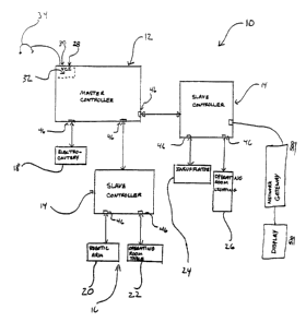
Figure 6 illustrates a block diagram of a control system 100, according to
another embodiment of the present invention. The control system 100 may be
accessed and utilized in an operating room, a doctor's office, or other
location, e.g.,
where surgery, medical attention, or examination is provided. For sake of
illustration, the control system 100 will be described with respect to an
operating
room setting, and thus will be referred to as an operation room control
system. The
155695-0108 -17- BR/jr
Express Mail No.: EK341755605US Patent Application
g.,.
CA 02353016 2001-07-12
control system I00 allows an operator (e.g., a surgeon, nurse, technician,
etc.) to
control operating room devices, retrieve, view, and manipulate patient records
and
information, and store information regarding the patient (e.g., notes, X-rays,
pictures, etc.) before, during, or after the surgery, examination, etc.,
conduct video
conferencing and remote surgery, and the like.
Referring to Figure 6, the operating room control system 100 includes a
master controller 110 that is coupled to a plurality of operating room devices
1141-
114N via respective communication ports 1181-118rr, where "N" is a positive
whole
number. The communication ports 1181-118N may include any type communication
port such as a serial port, parallel port, high speed serial bus, etc., and
combinations
thereof. The operating room devices 1241-114n~ may include any operating room
device as mentioned hereinabove such as a robotic arm, electrocautery device,
operating room table, operating room lights, insufflator, camera, and the like
The master controller 110 is coupled to a display device 128 for displaying
information (e.g., status of operating room devices, video captured by an
endoscope,
etc.) to the surgeon, doctor, nurse, etc. The master controller 110 also
includes a VCI
I22 for receiving selection and control commands, as d',escribed above and
shown in.
Figure 2, from an input device such as a microphone/headset 124. In one
embodiment, the master controller 110 includes a processor (e.g.,
microprocessor),
memory (random access and non-volatile), communication circuitry, etc. The
operating system may execute a speech recognition program for receiving
audible
commands to perform various tasks as discussed herein.
The master controller 110 is also coupled to a slave device 132 via
communication port 118 and communication lines 230. In one embodiment; the
slave device 132 is a device that performs actions and tasks requested by the
master
155695-0108 -28- , BR/jr
Express Mail No.: EK341755605US Patent Application
.~~,., _ -J--_-_--. _ ._
CA 02353016 2001-07-12
controller I20, and includes a processor (e.g., microprocessor), memory,
display
card, communication card (e.g., network interface card), and other components
well
known to those skilled in the art, none of which are shown: The slave device
132 is
coupled to a display 136 for displaying patient information, images, files,
and the
like, as will be discussed below. The slave device 132 rnay simply act as
another
"operating room device", with the purpose of retrievin;~, storing, and
displaying
patient information as requested by the master controller 110. The master
controller
110 may be coupled to the slave device 132 via serial port, parallel port,
network
connection, modem, high speed serial bus, radio frequency connection, and
infrared
connection.
It is important to note that the function of the slave device 132 as herein
described may be performed partially or entirely by the master controller 210.
In .
such a case, the patient information would be retrieved. directly from the
network
136 and displayed on the display 128.
The slave device 132 executes an operating system such as WindowsTM or
LinuxTM, and executes one or more application programs, modules, and/ or
drivers
for communicating with the master controller 110, retrieving, displaying, and
storing patient information, images, etc. on the display 136. In one
embodiment, the
slave device runs a web browser program such as the Internet ExplorerTM,
Netscape
NavigatorTM, etc. for accessing medical records over a rietwork (e.g.,
Internet,
Intranet, etc.).
The slave device 132 is coupled to a network 136, which may be a local area
network (LAN), a wide area network (WAN), etc., and a combination thereof. The
protocol used by the network may include TCP/ IP or ether suitable protocol.
Coupled to the network 136 are, among other things, servers 2401-140P, where
"P" is
155695-0108 -19- BR/jr
Express Mail No.: EK342755605US Patent Application
CA 02353016 2001-07-12
a positive whole number. The servers 1401-240P may be one or more dedicated
servers, department computers, and combinations thereof. The one or more
severs
and/ or computers may each include databases contaiiung patient information
including, among other things, MR, CT, X-ray, still-frame video, moving video,
ultrasound images, patient records, scheduling, financial information, and
inventory
(e.g., equipment usage). The data may be captured by a surgeon, doctor, nurse,
technician, e.g., during Radiology, Pathology, surgery,, examination, etc. For
example, one of the servers may be dedicated for storing X-rays of patients,
another
dedicated for storing patient records, and the like. The servers I40i-I40P may
be
physically located within the hospital, medical center, etc. Additionally, one
or
more of the servers 1401-I40P may be located at different locations of a
health
organization, affiliates, etc., but accessible via a closed network such as
network 236.
By connecting the slave device 132 to the network 136, patient information is
available for retrieval by the master controller 110 at any time including
during
surgery, examination, etc.
The master controller 110 also includes a language model (or vocabulary) for
audibly accessing patient information from various sorwces through the slave
controller 132. Examples of such audible commands available include, but are
not
limited or restricted to "get", "load", "display", "rotate", "store", etc.
Natural
language voice commands may also be used to identif~;~ which patient records
to
retrieve and view, to enlarge or shrink images, to adju:>t brightness and
contrast, to
page forward to the next image or back to the previous image, etc. A surgeon
may
capture and store images or video, record and store audio, or store text
audibly at
any time including during surgery or examination. Th.e stored information can
then
be "uploaded" as part of the patient information in the one or more servers
140z-
140P. The master controller 110 and/or slave device 1?~2 may include software
155695-0108 -20- BR/jr
Express Mail No.: EK341755605US Patent Application
CA 02353016 2001-07-12
and/or hardware for distinguishing the type of information stored (e.g., X-
ray,
patient information, etc.) and uploading the different 'types of information
to
different servers.
The slave device 132 is also coupled to a gateway/firewall 144 for
communicating over network cloud 148 such as the Internet or other network.
The
gateway/firewall 144 includes a controller (not shown) that controls traffic
within
the network 136 and provides access to the outside network cloud 148. The
gateway/firewall 144 may also perform translation from one protocol to
another,
routing functions, etc. Also coupled to the network cloud 148 are one or more
remote servers 1521-252Q (where "Q" is a positive whoae number). The remote
servers 2521-152Q may be located at one or more remote hospitals, health
organizations, and/or dedicated locations (e.g., central databases).
Consequently, a
doctor can obtain patient information (e.g., picture of ~~ patient's heart
valve) from a
hospital that the patient previously visited, while performing emergency heart
valve
surgery on the patient. The slave device 132, under command of the master
controller 120, can retrieve patient information from and store patient
information to
one or more remote servers 1521-15?~.
Through the use of a web browser, the patient information may be sent to the
slave device I32 in a format to be displayed by either the display 236 or the
display
128 connected to the master controller 110, in a web browsable format.
To effectuate the display of patient information in a web browsable format,
using HyperText Markup Language (HTML) or some .other well known web format,
the data is provided to the slave device 132 in that forrnat. An access port,
essentially consisting of one or more URLs provides a aocation for the web
browser
to obtain patient information. The one ormore URLs provide an interface into
the
155695-0108 -2I- BR/ jr
Express Mail No.: EK341755605US Patent Application
__ ._._-~_ _..____~...... _.-.~.-
~. _ __.___.__
CA 02353016 2001-07-12
network 136 and network cloud 148. The web browses can display an index of
medical records, images, etc., with voice-activated links to more detailed
information.
Figure 7 shows a logical connection between they master controller 110 and the
operating room devices 114-114N and the slave device 132. Referring to Figure
7,
the master controller 110 is coupled to the operating room devices 1141-114rr
via
respective modules 1701-170N, and is coupled to the slave device 132 via
module 174.
The modules are software blocks or drivers that translate signals and/or
commands
between the master controller 110 and the operating room devices 1141-114N,
and
the slave device 132. In one embodiment, a module is ~~ dongle that translates
signals from the master controller 110 to a specific forrrtat (e.g., protocol,
timing, etc.)
of the particular operating room device or slave device, and vice versa: Thus,
the
modules may be different depending on the device bevng controlled. Each of the
modules 1141-114rr continuously "pings" or monitors the device being
controlled to
confirm that device is operational. This allows the master controller 110 to
quickly
determine whether a device has malfunctioned and provide prompt notification,
which may be critical in the operating room envirorune~nt. In another
embodiment,
the modules 114r114N may be hardware devices or cornbination of
hardware/software devices, where the hardware devices include circuitry for
performing translation of signals, timing, and the like.
Figure 8 shows a logical connection of the module 274 that interfaces the
master controller 110 to the slave device 132. The master controller 110
issues
service requests or commands 210. If a voice commandi received by the master
controller 110 is a recognized command for querying tree slave device 132 for
information, the master controller 110 forwards a service request 210 (e.g.;
"get
angiography information") to the module 174. The module 174 translates and/ or
255695-0108 _~2_ gR~~r
Express Mail No.: EK341755605US Patent Application
CA 02353016 2001-07-12
processes the command into a format recognized by th.e slave device and
forwards a
trigger code command 214 to the slave device 132. The slave device 132
receives the
command for processing. The slave device 132 then sends status commands 218
back to the module 174, indicating the status of the request, retrieved
information,
etc. The module 174, in turn, transmits the status command 222 to the master
controller 110, indicating the status. For example, if the angiography
information of
a patient is not available, then the status will indicate this information.
The slave
device 132 may also deactivate any portion of the display 126 {Figure 6)
pertaining
to the angiography information to indicate that the information is not
available. The
master controller.110 continually sends commands (e.g., in short intervals) to
the
slave device 132 for obtaining the operational status of the slave device 132.
Figure 9 illustrates a logical block diagram of the slave device 132,
according
to one embodiment of the present invention. Referring to Figure 9, the slave
device
132 includes a serial port event handler 240 that receives trigger codes from
and
sends status information to the module 174 (Figure 8). 'The event handler 240
forwards the received trigger codes to a graphical user :interface (GUI) and
control
Iogic block 244. The GUI and control logic block 244 sends commands to a
hypertext
dynamic parsing module 248, which then transmits the request to one or more
servers, located on the network 136 (e.g., Intranet) and/or on the network
cloud 148
(e.g.; Internet). In one embodiment, the information transmitted from servers
to the
slave device 132 is in hypertext format. The hypertext alynamic parsing module
248
receives the hypertext data from one or more servers, parses the data for
images,
text (e.g., patient records), video clips; dynamic links, etc., and forwards
the parsed
information to the GUI and control logic block 244. The GUI and control Iogic
block
244 drives the information to a browser driving module 252 for displaying the
information on the display 136.
155695-0108 -23- BR~~r
Express Mail No.: EK341755605US Patent Application
~,a,.
CA 02353016 2001-07-12
Also coupled to the GUI and control logic block. 244 is a driver information
parser module 256, which provides configuration information to the GUi and
control logic block 244. The module 256 is loaded once during initialization.
It
retrieves information from a configuration or device resource file, and
forwards the
information to the GUI and control logic block 244. The configuration
information
indicates resources available, such as, for example, the voice commands
available,
the menu structure to be displayed on the display 136, timing requirements,
and the
like.
The GUI and control logic block 244 receives the trigger code, translates the
code based on the current patient, and forwards a command to a server (e.g.,
patient
#2100, angiography). The server receives the command, retrieves the
angiography
information for patient #2100, if any, from its database, and sends the
information
back. The parsing module parses the information.
Figure 10 illustrates a block diagram of a system 300, according to another
embodiment of the present invention. Referring to Figure 10, the system 300
includes a slave device 310, which comprises the slave dLevice 132 of Figure
6. Other
devices such as the master controller 110, operating room devices 1141-124N,
display
devices 128 and 136, and microphone/headset 124 have not been shown for sake
of
clarity. In an embodiment where the master controller 7.10 performs the
functions of
the slave device 132, the slave device 310 comprises the master controller 120
(Figure
6). The system 300 is developed for accessing disparate :medical data across a
network 315, which represents a local area network, wide area network, direct
connection, or combinations thereof.
The system 300 includes an index server 320 that is coupled to the network
315. The index server 320 accepts queries from the slave device 310 for
medical data
155695-0108 -24- BR/ jr
Express Mail No.: EK341755605US Patent Application
CA 02353016 2001-07-12
about a specific patient and provides a reference list o:E records available
about that
specific patient. The slave device 310 and the index server 320 may be located
within the same hospital, group of hospitals, or remotely from each other. The
medical data are derived from a discrete set of electroW c medical record
servers
3251-3258 (where "R" is a positive whole number). The servers 3251-3258 may be
located remotely from each other. For example, the servers 3251-3258 may
represent
servers located domestically and/or globally of one or more of the following:
hospitals, medical centers, centralized medical data databases, and the like.
The medical data referenced may be of any variety including photographic
(still or moving), textual, aural, or other patient data. In one embodiment,
the index
server 320 receives requests from the slave device 310 ~~nd responds with an
HTML
protocol that reflects the results of the patient data located. Further, the
index server
320 may format certain datas in an HTML protocol to facilitate display of such
data
by the slave device 310.
The present invention may be implemented as a method, apparatus, system,
etc. When implemented in software, the elements of the present invention are
essentially the code segments to perform the necessary tasks. The program or
code
segments can be stored in a processor readable medium~~ or transmitted by a
computer data signal embodied in a carrier wave over a, transmission medium or
communication link. The "processor readable medium" may include any medium
that can store or transfer information. Examples of the processor readable
medium
include an electronic circuit; a semiconductor memory device, a ROM; a flash
memory, an erasable ROM (EROM), a floppy diskette, a CD-ROM, an optical disk,
a
hard disk, a fiber optic medium, a radio frequency (RF) Link, etc. The
computer data
signal may include any signal that can propagate over a transmission medium
such
as electronic network channels, optical fibers, air, electromagnetic, RF
links, etc.
155695-0108 -25- BR/jr
Express Mail No.: EK341755605US Patent Application
CA 02353016 2001-07-12
While certain exemplary embodiments have been described and shown in the
accompanying drawings, it is to be understood that such embodiments are merely
illustrative of and not restrictive on the broad invention, and that this
invention not
be limited to the specific constructions and arrangements shown and described,
since various other modifications may occur to those ordinarily skilled in the
art.
155695-0I08 -26- BR/jr
Express Mail No.: EK341755605US Patent Application