Language selection

Search

Patent 2353059 Summary

Third-party information liability

Some of the information on this Web page has been provided by external sources. The Government of Canada is not responsible for the accuracy, reliability or currency of the information supplied by external sources. Users wishing to rely upon this information should consult directly with the source of the information. Content provided by external sources is not subject to official languages, privacy and accessibility requirements.

Claims and Abstract availability

Any discrepancies in the text and image of the Claims and Abstract are due to differing posting times. Text of the Claims and Abstract are posted:

  • At the time the application is open to public inspection;
  • At the time of issue of the patent (grant).
(12) Patent: (11) CA 2353059
(54) English Title: HAMMER
(54) French Title: MARTEAU
Status: Deemed expired
Bibliographic Data
(51) International Patent Classification (IPC):
  • B25D 1/00 (2006.01)
  • B25G 1/01 (2006.01)
(72) Inventors :
  • LIN WU, LI-TU (Taiwan, Province of China)
(73) Owners :
  • LIN WU, LI-TU (Taiwan, Province of China)
(71) Applicants :
  • LIN WU, LI-TU (Taiwan, Province of China)
(74) Agent: BULL, HOUSSER & TUPPER LLP
(74) Associate agent:
(45) Issued: 2005-04-12
(22) Filed Date: 2001-07-13
(41) Open to Public Inspection: 2003-01-13
Examination requested: 2001-07-13
Availability of licence: N/A
(25) Language of filing: English

Patent Cooperation Treaty (PCT): No

(30) Application Priority Data: None

Abstracts

English Abstract


A hammer includes a composite material handle having a connecting
portion formed on one end of the composite material handle. A head is
encircled in the connecting portion of the handle and has a flat working face
formed on one end. An annular groove is defined in a middle portion of the
head to receive the connection portion of the handle. A through hole is
transversely defined in the middle portion of the head and communicates with
the annular groove. A cushion core is securely inserted in the through hole in
the head to absorb the shock generated when the hammer is used.


Claims

Note: Claims are shown in the official language in which they were submitted.


5

The embodiment of the invention in which an exclusive property or privilege is
claimed are defined as follow:
1. A hammer comprising:
a composite material handle having a connecting portion formed on one end
of the composite material handle; and
a head encircled in the connecting portion of the handle and including:
a flat working face formed on an end of the head;
an annular groove defined around a middle portion of the head to
receive the connection portion of the handle;
a through hole transversely defined in the middle portion of the head and
communicating with the annular groove; and
a cushion core securely inserted in the through hole in the head
wherein the cushion core comprises:
a foam material ply;
a composite material ply coated around the foam material ply;
and
a cushion material ply coated around the composite ply after the foam
material ply and the composite material ply have been combined with each other
by
being heated and pressed.
2. The hammer with a composite handle as claimed in claim 1 further
comprising an absorbing device mounted in the handle and including:
a closed casing mounted in the handle;
multiple partitions formed in the closed casing to divide the closed casing
into multiple chambers; and
multiple steel balls in each of the chambers.


6
3. The hammer with a composite handle as claimed in claim 1 further
comprising an absorbing device mounted in the handle and including:
a closed casing mounted in the handle;
multiple partitions formed in the closed casing to divide the closed casing
into multiple chambers; and
multiple steel balls in each of the chambers.
4. The hammer as claimed in claim 1, wherein the composite material handle is
made of carbon fiber.
5. The hammer as claimed in claim 1, wherein the composite material handle is
made of glass fiber.

Description

Note: Descriptions are shown in the official language in which they were submitted.


CA 02353059 2004-05-11
1
1 BACKGROUND OF THE INVENTION
2 1. Field of the Invention
3 The present invention relates to a hammer, and more particularly to a hammer
4 with a composite material handle.
2. Description of Related Art
C With reference to Fig. 5, a conventional hammer in accordance with the prior
art
7 comprises a head {60) made of steel alloy and a wooden handle (50). A
through hole (61 )
8 is defined in a middle portion of the head (60) and one end of the handle
(50) is inserted
9 into and securely received in the through hole (61) of the head (60). The
conventional
hammer has several disadvantages including the following.
11 1. The structure of the conventional hammer is unsteady. The head (CO) may
12 detach from the handle {50) due to the shock and vibrations of the hammer
when it
13 strikes an object. The conventional hammer can be very dangerous.
14 2. The conventional hammer has no shock absorbing capability. The shock is
directly transformed to a user's hand and makes the user feel uncomfortable.
1 G 3. Marking the conventional hammer is difficult. When a permanent
identifying
17 mark needs to be made on the hammer, the cost is high because the head (60)
is made of
18 steel and the handle (60) is made of wood.
19 The present invention has arisen to mitigate and/or obviate the
disadvantages of
the conventional hammer.
21 SUMMARY OF THE INVENTION
22 The main objective of the present invention is to provide a hammer with an
23 integral or interlocking structure to make the hammer safer and that can
transmit an
24 equal or greater force to an object struck while absorbing shock normally
transmitted to
the user. To achieve the objective, the hammer in accordance with the present
invention


CA 02353059 2004-05-11
2
1 comprises an essentially conventional head and a composite material handle
having a
2 connecting portion formed on one end of the composite material handle. The
head is
3 encircled in the connecting portion of the handle and has a working face
formed on at
4 least one end. An annular groove is defined in a middle portion of the head
to receive the
connection portion of the handle. A through hole is transversely defined in
the middle
6 portion of the head and communicates with the annular groove. A cushion core
is
7 securely inserted into the through hole in the head to absorb the shock when
the hammer
8 is used to prevent the user's hand from becoming numb.
9 Further benefits and advantages of the present invention will become
apparent
after a careful reading of the detailed description with appropriate reference
to the
11 accompanying drawings.
12 BRIEF DESCRIPTION OF THE DRAWINGS
13 Fig. 1 is a perspective view of a hammer in accordance with the present
14 invention;
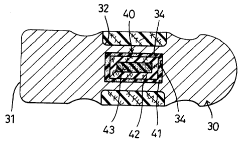
Fig. 2 is an enlarged cross sectional side plan view of the hammer in Fig. l;
16 Fig. 3 is an enlarged cross sectional top plan view of the hammer in Fig.
l;
17 Fig. 4 is an enlarged cross sectional side plan view of a handle of the
hammer in
18 Fig. l; and
19 Fig. 5 is a perspective view of a conventional hammer in accordance with
the prior art.
DETAILED DESCRIPTION OF THE INVENTION
21 With reference to the drawings and initially to Figs. 1-3, a hammer in
22 accordance with the present invention comprises handle (10) and a head (30)
securely
23 attached perpendicularly to one end of the handle ( 10). The handle is made
of composite
24 material, such as carbon fiber or glass fiber, and the head (30) is made of
steel alloy.
The head (30) includes two ends. one forming A flat working face (31 ) is
formed


CA 02353059 2004-05-11
3
1 on one end, and a ball peen (not numbered) is formed on the other end. An
annular
2 groove (32) is defined in the middle portion of the head (30) and a through
hole (34) is
3 transversely formed through the head (30). The through hole (34)
communicates with
4 the annular groove (32).
A cushion core (40) is securely inserted into the through hole (34) in the
head
6 (30). The cushion core (40) comprises a foam ply (43) coated with a
composite material
7 ply {42). A cushion material ply (41 ) coats the composite material ply (42)
after the foam
8 material play (43) and the composite material ply (42) are combined to each
other by
9 being heated and pressed. Then one end of the handle ( 10) forms a
connecting portion
(11) to securely encircle a middle portion of the head (30) to form a T shaped
hammer
11 and hold the cushion core (40) in place.
12 With reference to Fig. 4, the hammer in accordance with the present
invention
13 further comprises a shock absorbing device ( 15) mounted in the handle (
10). The
14 absorbing device (15) includes a closed casing (151) and multiple
partitions (152)
formed to divide the casing (151) into multiple chambers (150) to loosely hold
a quantity
16 of steel balls (153) in each of the chambers (150). The steel balls (153)
in the absorbing
17 device (15) add the momentum of the moving steel balls (153) to the force
of the head
18 (30) when striking an object and can absorb the shock transmitted to the
handle (10) to
19 prevent the user's hand from becoming numb.
As described above, the hammer in accordance with the present invention
21 includes several advantages as follow.
22 1. The hammer of the present invention is light and has a stronger
structure
23 because the handle of the present invention is made of composite material
such as carbon
24 fiber or glass fiber.
2. The connecting portion ( 11) of the handle ( 10) securely encircles in the

CA 02353059 2004-05-11
4
I groove in the head (30) by being heated and pressed so that the connection
of the handle
2 and the head is secure and effectively prevents the head (30) from detaching
from the
3 handle ( 10).
4 3. The cushion core (40) is securely mounted in the head (30) so that the
shock is
partially absorbed by the cushion core (40) and the absorbing device ( 15) is
mounted in
G the handle ( 10) to absorb additional shock to prevent a user's hand from
becoming
7 numb.
8 4. A trademark or characters can easily be formed on the outer periphery of
the
9 handle ( 10) when the hammer is heated and pressed due to the
characteristics of the
composite material and forming method.
I 1 Although the invention has been explained in relation to its preferred
12 embodiment, it is to be understood that many other possible modifications
and variations
13 can be made without departing from the spirit and scope of the invention as
hereinafter
14 claimed.

Representative Drawing
A single figure which represents the drawing illustrating the invention.
Administrative Status

For a clearer understanding of the status of the application/patent presented on this page, the site Disclaimer , as well as the definitions for Patent , Administrative Status , Maintenance Fee  and Payment History  should be consulted.

Administrative Status

Title Date
Forecasted Issue Date 2005-04-12
(22) Filed 2001-07-13
Examination Requested 2001-07-13
(41) Open to Public Inspection 2003-01-13
(45) Issued 2005-04-12
Deemed Expired 2006-07-13

Abandonment History

There is no abandonment history.

Payment History

Fee Type Anniversary Year Due Date Amount Paid Paid Date
Request for Examination $200.00 2001-07-13
Application Fee $150.00 2001-07-13
Maintenance Fee - Application - New Act 2 2003-07-14 $50.00 2003-06-25
Maintenance Fee - Application - New Act 3 2004-07-13 $50.00 2004-07-06
Final Fee $150.00 2005-01-31
Owners on Record

Note: Records showing the ownership history in alphabetical order.

Current Owners on Record
LIN WU, LI-TU
Past Owners on Record
None
Past Owners that do not appear in the "Owners on Record" listing will appear in other documentation within the application.
Documents

To view selected files, please enter reCAPTCHA code :


To view images, click a link in the Document Description column. To download the documents, select one or more checkboxes in the first column and then click the "Download Selected in PDF format (Zip Archive)" or the "Download Selected as Single PDF" button.

List of published and non-published patent-specific documents on the CPD .

If you have any difficulty accessing content, you can call the Client Service Centre at 1-866-997-1936 or send them an e-mail at CIPO Client Service Centre.


Document
Description 
Date
(yyyy-mm-dd) 
Number of pages   Size of Image (KB) 
Abstract 2001-07-13 1 19
Drawings 2001-07-13 5 70
Description 2001-07-13 4 168
Representative Drawing 2002-03-06 1 4
Cover Page 2002-12-20 1 28
Claims 2001-07-13 2 53
Abstract 2004-05-11 1 16
Description 2004-05-11 4 153
Claims 2004-05-11 2 46
Representative Drawing 2004-09-01 1 15
Cover Page 2005-03-18 1 39
Assignment 2001-07-13 5 116
Fees 2003-06-25 1 32
Prosecution-Amendment 2003-07-22 1 31
Prosecution-Amendment 2004-01-07 2 66
Prosecution-Amendment 2004-05-11 10 305
Fees 2004-07-06 1 32
Correspondence 2005-01-31 1 29