Note: Descriptions are shown in the official language in which they were submitted.
P,
CA 02353134 2001-07-16
DIFFERENTIAL HYDROSTATIC TRANSMISSION SYSTEM
BACKGROUND OF THE IN~~ENTION
1. Field of the Invention
The invention relates to hydrostatic transmission systems and use of such a
hydrostatic transmission system in powering a winch.
2. Background Art
Well logging involves recording data related to one or more characteristics
of subterranean formations penetrated by a borehole. Many types of well logs
are
recorded by appropriate downhole instruments placed in a housing called a
sonde.
In wireline-conveyed well logging, the sonde is lowered into the borehole by
means of an armored electrical cable wound on the drum of a winch. The
measurements are made as the sonde passes the various formations, and data
signals are transmitted through the cable to an acquisition system at the
earth's
surface. Generally, the sonde can be lowered .quickly into the borehole and
retrieved quickly from the borehole when it is not; acquiring data. However,
the
physics and design of some well logging instrmrients require that the sonde be
moved precisely inside the borehole, usually at a low speed, while acquiring
data.
A drive system is used to drive the winch drum so that the cable to which the
sonde is attached can be payed out or retrieved at desired speeds. Typically,
the
drive system includes a prime mover, such as an internal combustion engine,
and a
hydrostatic transmission system for transmitting power from the prime mover to
the winch drum.
Conventional hydrostatic transmission systems include a hydraulic pump,
usually a variable-displacement hydraulic pump, and a hydraulic motor, usually
a
variable-displacement hydraulic motor. The hydraulic pump transfers power from
the prime mover to the hydraulic motor, and the hydraulic motor in turn
applies a
1
CA 02353134 2001-07-16
T .
torque to the winch drum. In operation, the prime mover is typically set to
operate
at a predetermined speed via an engine throttle or the like. The speed of the
winch
drum is then regulated by controlling the displacc;ments of one of the
hydraulic
elements of the hydrostatic transmission system. Conventional hydrostatic
transmission systems, however, tend to become unstable when the flow rate of
the
hydraulic pump and the rotational speed of the hydraulic motor are reduced to
accommodate very low drum speeds. Such instability may affect the quality of
the
measurements made by the logging instrument as well as degrade the service
performance of the hydrostatic transmission system. As a result, logging
speeds
have typically been limited to the stable range of the hydrostatic
transmission
system.
Several solutions have been proposed for overcoming instability of the
hydrostatic transmission system at low speeds., For example, U.S. Patent
5,355,675 issued to Mayhugh et al. discloses a stable closed hydrostatic
rotary
power transmission system which can be used to transmit power from an engine
to
a winch. The hydrostatic rotary power transmission system disclosed in the
Mayhugh et al '675 patent has a wide dynamic speed control range and includes
a
hydrostatic motor, a variable-displacement hydraulic pump, and a two-position
control device. The transmission system may operate in one of two modes:
normal made and fine-speed control mode. In the normal mode, the two-position
control device interconnects the pump with the motor through a first circuit,
and
the operation of the motor speed is a function of the displacement of the
pump. In
a fine speed control mode, the two-position control device disables the first
circuit
configuration and interconnects the pump with the motor through a second
circuit.
In this mode, the motor speed is a function of the flow rate through a
proportional-
flow valve downstream of the motor.
2
CA 02353134 2001-07-16
SUMMARY OF THE INVENTION
One aspect of the invention is a hydrostatic transmission system for driving
a rotatable member, which includes a differential having an output rotatably
coupled with the rotatable member. The hydrostatic transmission system further
includes a first hydrostatic drive operatively coupled to a first input of the
differential and a second hydrostatic drive operatively coupled to a second
input of
the differential. The output of the first hydrostatic drive is rotatable in a
first
selected direction and at a first selected speed, the output of the second
hydrostatic
drive is rotatable in a second selected direction and at a second selected
speed. A
rotational speed and direction of the output of the differential is related to
the
algebraic sum of the rotational speeds and directions of the outputs of the
two
hydrostatic drives.
Another aspect of the invention is a method for driving a rotatable member
which includes controlling a first hydrostatic drive to a first input of a
differential
at a selected speed in a first selected direction, and controlling a second
hydrostatic drive to rotate a second input of a differential at a second
selected
speed and in a second selected direction. The; first and second speeds and
directions are selected to provide a selected output speed and rotation
direction of
the differential, and consequently, the rotatable; member, which is rotatably
coupled to the output of the differential.
Another aspect of the invention is a winch system which comprises a
rotatably supported drum, a differential having an output coupled to the
rotatably
supported drum, a first hydrostatic drive having an output coupled to a first
input
of the differential, and a second hydrostatic drive having an output coupled
to a
second input of the differential. The output oiF the first hydrostatic drive
is
rotatable in a first selected direction, the output of the second hydrostatic
is
rotatable in a second selected direction, and a rotational speed of the output
of the
3
CA 02353134 2001-07-16
differential is related to algebraic sum of the rotational speeds and
directions of the
output of the hydrostatic drives.
Other aspects and advantages of the invention will be apparent from the
following description and the appended claims.
BRIEF DESCRIPTION OF THE DRAWINGS
Figure 1 is a block diagram of a winch system.
Figure 2 is a circuit diagram of a hydrostatic transmission system according
to one embodiment of the invention.
Figures 3 and 4 show examples of control graphs used to control the
hydrostatic transmission system shown in Figure 2.
Figure 5 is a circuit diagram of a hydrostatic transmission system according
to another embodiment of the invention.
Figure 6 shows an example of a control graph for the hydrostatic
transmission system shown in Figure 5.
Figure 7 is a circuit diagram of a hydrostatic. transmission system according
to another embodiment of the invention.
Figure 8 shows an example of a control graph for the hydrostatic
transmission system shown in Figure 7.
DETAILED DESCRIPTION OF THE INVENTION
Various embodiments of the invention will now be described with reference
to the accompanying figures. Figure 1 is a block diagram of a winch system 2
which includes a winch 4 having a rotatably supported winch drum 5, an
operator
control console 6, a prime mover 8, for example, a diesel engine, and a
hydrostatic
transmission system 10. The winch 4 is used to move a load 12. In well
logging,
the load 12 could be a sonde, for example. The load 12 would be attached to
the
4
CA 02353134 2001-07-16
end of a cable 13 that is wound on the winch drum S. When the winch drum 5 is
rotated, the cable 13 is either extended or retrieved, depending on the
direction of
rotation of the winch drum 5. The speed at which the winch drum 5 rotates is
controllable from the operator control console 6. The hydrostatic transmission
system 10 delivers power from the prime mover 8 1:o the winch drum 5 in
response
to control signals from the operator control console; 6 to drive the winch
drum 5 in
the selected direction and at the selected speed.
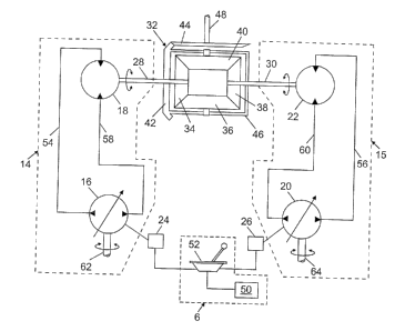
Figure 2 shows an hydraulic circuit diagram for the hydrostatic
transmission system 10 according to one embodiment of the invention. The
hydrostatic transmission system 10 includes two closed-loop hydrostatic drive
circuits 14, 15. Closed-loop hydrostatic drive ciircuit 14 includes an
hydraulic
pump 16 and an hydraulic motor 18. Closed-loop hydrostatic drive circuit 15 in
this example also includes an hydraulic pump 2;0 and an hydraulic motor 22.
Various types of hydraulic pumps are known in the art. See, for example,
Sullivan, James A., Fluid Power: Theory and Applications, Prentice-Hall, Inc.
(1998). The hydraulic pumps 16, 20 may be positive-displacement type. Positive-
displacement hydraulic pumps transfer a substantially constant volume of fluid
for
each cycle of operation. More preferably, the hydraulic pumps 16, 20 are
"variable-displacement" pumps. A variable displacement pump is one in which
the displacement volume per cycle of the pump's operation can be adjusted.
Various types of variable-displacement pumps are known in the art. One common
design uses a swash plate to adjust the volumetric flow rate of the pump. The
volumetric flow rate is adjusted by changing the .angle of the swash plate,
either
mechanically or by the action of a yoke-actuating piston, for example.
The adjustment of the internal mechanisms. e.g., swash plates (not shown),
which control the volumetric flow rates of the; hydraulic pumps 16, 20 are
controlled in this embodiment by actuatable electronic displacement controls
24,
5
CA 02353134 2001-07-16
26, which in this embodiment., for example, are displacement solenoids.
Preferably, the hydraulic pumps 16, 20 include means for controlling their
output
flow in either direction, i.e., means for reversing t:he suction and discharge
ports
on the pump. Reversing valves (not shown) may also be used to change the flow
direction of either or both of the pumps 16, 20. The hydraulic motors 18, 22
receive pressurized fluid from the hydraulic pumps 16, 20 and convert the
energy
in the pressurized fluid to the turning motion of motor output shafts 28, 30,
respectively. The hydraulic motors 18, 22 rotate the respective output shafts
28,
30 in either direction, i.e., forward or reverse, depending on direction of
fluid flow
through the motor. Hydraulic motors are available as either fixed- or variable-
displacement units so that speed variation with rotation in either direction
is
possible even with a fixed volumetric flow rate through the motor. Various
hydraulic motor designs are known in the art. Sec, for example, Sullivan,
James
A., Fluid Power ~ Theory and Applications, supra.
The output shafts 28, 30 of the hydraulic motors 18, 22 are coupled to
respective inputs of a differential 32. In one embodiment, the differential 32
comprises bevel gears 34-40. The shafts 28 and 30 are coupled to input bevel
gears 34 and 38, respectively. The differential 32 also includes bevel gears
42 and
44. Gears 42 and 44 can also be hypoid gears. Accordingly, the form of the
gears
is not meant to limit the invention. A carrier 46 is .attached to bevel gear
42 and is
coupled to bevel gears 36 and 40. The rotary motion of the motor output shafts
28
and 30 is transmitted to bevel gears 36 and 40 by differential input bevel
gears 34
and 38. The rotary motion of bevel gears 36 and 40 is in turn transmitted to
the
bevel gear 42 through the carrier 46. Finally, tile motion of bevel gear 42 is
transmitted to the bevel gear 44. An output shaft 48 is coupled to the bevel
gear
44 so as to turn with the bevel gear 44. The output shaft 48 transmits the
torque
necessary to rotate the winch drum 5 (shown in Figure 1 ). The speed of the
output
6
CA 02353134 2001-07-16
shaft 48 is determined by the configuration of the gears in the differential
32 and
the speed and rotation direction of the motor output shafts 28, 30. The speed
of
the differential output shaft 48 can be controlled by appropriately selecting
the
speed and direction of rotation of each of the motor output shafts 28, 30. The
differential 32 could be configured differently from what is shown in the
drawing,
as well known in the art. For example, the differential 32 could consist of a
train
of planetary gears or other types of gears. Accordingly, the form of the
differential shown in Figure 2 is not meant to limit the scope of the
invention.
The differential 32 can operate, for purposes of explaining its output speed,
in a "differential mode" or a "summation mode". At the operator control
console
6, an operator may use a mode selector 50 to select the mode. Selection of the
mode in one example consists of selecting the direction of rotation of each of
the
hydraulic motors 18, 22. As will be further explained, the speed and direction
of
rotation of each of the motors depends on the desired rotation speed of the
winch
drum (5 in Figure 1 ). >3ased on the selected mode, the operator may then use
a
control device 52, e.g., a joystick controller, to~ control the operation of
the
hydraulic pumps 16, 20. The control device 52 sends a signal to the electronic
displacement controls 24, 26, which then control the internal mechanisms in
the
hydraulic pumps 16, 20, respectively, so that the desired amount of fluid is
pumped out of the hydraulic pumps 16, 20. The pressurized fluid pumped out of
the hydraulic pumps 16, 20 flows through conduits 54, 56, respectively, to the
hydraulic motors 18, 22, thereby providing power to the hydraulic motors 18,
22.
The hydraulic motors 18, 22 convert the energy in the pressurized fluid to
rotary
motion of the motor output shafts 28, 30, as prcwiously explained. The fluid
pumped to the hydraulic motors 18, 22 returns to the inlet manifolds of the
hydraulic pumps 16, 20 through conduits 58, 60, respectively.
The rotation speed and direction of the differential output shaft 48 is
related
7
CA 02353134 2001-07-16
to the algebraic sum of the proportional speeds of the motor output shafts 28,
30.
The term proportional is used because the speed of the differential output
shaft 48
depends on the gear configuration, e.g., the number of teeth on the gears 32-
38
which transmit the motion of the input shafts 28, 3.0 to the output shaft 48.
If the
motor output shafts 28 and 30 are rotating to turn their associated
differential input
gears in the same direction, the speed of the differential output shaft 48
will be
related to the sum of the speeds of the motor output: shafts 28 and 30. On the
other
hand, if the motor output shafts 28 and 30 are rotating in opposite
directions, the
speed of the differential output shaft 48 is the relatf;d to the difference
between the
speeds of the input shafts 28 and 30. Algebraically, a sign (positive or
negative)
can be arbitrarily assigned to the rotation speed of each of the motor output
shafts
to describe which direction the associated differential input gear is being
rotated.
Figures 3 and 4 show examples of control graphs which show the individual
speeds of the hydrostatic drive circuits 14, 15, i.e., the speeds of the motor
output
shafts 28, 30, in the differential and summation mode, respectively, to
achieve
substantially infinite variability of the differential output shaft 48 speed,
from full
speed down (paying out the cable on the winch drum), through and including
zero,
to full speed up (reeling in the cable onto the winch drum).
The control graph shown in Figure 3 is for the differential mode. For the
example shown in Figure 3, the transmission system is set up such that the
load 12
(shown in Figure 1) attached to the cable 13 (shown in Figure 1) on the winch
drum 5 (shown in Figure 1) travels in the upward direction (out of a wellbore)
when the rotation motor output shaft 28 (shown in Figure 2) is clockwise, and
travels in the downward direction (into the wellbore) when the rotation of
motor
output shaft 28 (shown in Figure 2) is counterclockwise. In Figure 3, curves
28a,
28b represent the speeds of motor output shaft 28 (chown in Figure 2), curves
30a,
30b represent the speeds of motor output shaft 30 (shown in Figure 2), and
curves
8
CA 02353134 2001-07-16
48a, 48b represent the speeds of the differential output shaft 48 (shown in
Figure
2). The speed curve 48a is the resultant of the speed curves 28a and 30a, and
the
speed curve 48b is the resultant of the speed curves 28b and 30b. In the
differential zone 66, motor output shaft 28 (shown in Figure 2) rotates in the
counterclockwise direction, as shown by the portion of the curve 28a within
the
differential zone 66, and motor output shaft 30 (shown in Figure 2) rotates in
the
clockwise direction, as shown by the portion of the curve 30a within the
differential zone 66. Similarly, in the differential zone 68, motor output
shaft 28
(shown in Figure 2) rotates in the clockwise direction, as shown by the
portion of
the curve 28b within the differential zone 68, amd the motor output shaft 30
(shown in Figure 2) rotates in the counterclockwise direction, as shown by the
portion of the curve 30b. In the differential zones 66, 68, the speed 48a, 48b
of
the differential output shaft 48 (shown in Figure 2) is determined by the
difference
between the speed 28a, 28b of motor output shaft 28 (shown in Figure 2) and
the
speed 30a, 30b of the motor output shaft 30 (shown in Figure 2), respectively.
The control graph shown in Figure 4 is for the summation mode. In the
summation mode, the motor output shafts 28 and 30 (shown in Figure 2) both
rotate their respective differential input gears in the same direction,
regardless of
the direction in which the load 12 (shown in Figure 1) is traveling. In this
example, the transmission system is set up such that the load 12 (shown in
Figure
1) travels in the upward direction when the rotation of motor output shaft 28
(shown in Figure 2) and the rotation of motor output shaft 30 (shown in Figure
2)
are both clockwise. The load 12 (shown in Figure 1 ) travels in the downward
direction when the rotation of motor output shaft 2;8 and the rotation of the
motor
output shaft 30 are counterclockwise. In Figure 4, curves 28a, 28b represent
the
speeds of motor output shaft 28 (shown in Figure 2), curves 30a, 30b represent
the
speeds of motor output shaft 30 (shown in Figure 2), and curves 48a, 48b
9
CA 02353134 2001-07-16
represent the speeds of the differential output shaft 48 (shown in Figure 2).
The
speed curve 48a is the resultant of the speed curves 28a and 30a, and the
speed
curve 48b is the resultant of the speed curves 28b and 30b. In the summation
mode, the speed 48a, 48b of the differential output shaft 48 (shown in Figure
2) is
determined by the sum of the speed 28a, 28b of motor ouput shaft 28 and the
speed 30a, 30b of motor output shaft 30 (shown in Figure 2), respectively. The
summation mode, does not generally provide for <~ zero speed at the
differential
output shaft 48 (shown in Figure 2), unless the motor output shafts 28 and 30
(shown in Figure 2) both have zero speeds, i. e. , the hydraulic motors 18, 22
(shown in Figure 2) are turned off. When it is desired to obtain very low
speeds or
zero speed, the differential mode is the more appropriate mode of operation.
Referring to Figure 2, it should be noted that the control device 52 is used
to
control the direction in which the motor output shafts 28, 30 are rotating.
The
control device 52 sends signals to the hydraulic pumps 16, to reverse flow
direction. This reverse in flow direction is communicated to the hydraulic
motors
18, 22. Alternatively, as previously explained, the flow direction through
each of
the motors 18, 22 can be selected using a reversing valve (not shown).
The hydrostatic transmission system described above provides certain
advantages over prior art hydrostatic drive systc;ms, especially when used in
wireline-conveyed well logging. One advantage i.s that the transmission system
allows the speed of the winch drum 5 (shown in Figure 1) to be precisely
controlled, particularly at very low rotation speeds, by operating the
transmission
system in the differential mode. When the logging sonde is acquiring data,
however, using the differential mode makes it possible to move the sonde at
very
low speeds, even at zero speed, while operating the motors 18, 22 (shown in
Figure 2) above their individual minimum stable speed limits. Because the
motors
18, 22 (shown in Figure 2) can operate above their individual minimum stable
CA 02353134 2001-07-16
speeds limits while achieving very low differer.~tial output (and consequently
winch drum) speeds, a region of instability of prior art winch drive hydraulic
transmission systems can be avoided. When the logging sonde is not acquiring
data, for example, the transmission system can operated in the summation mode
so
that the logging sonde can be lowered into the borehole or retrieved from the
borehole very quickly.
The hydrostatic transmission system shov~rn in Figure 2 illustrates one
embodiment of a differential hydrostatic drive system which can be used to
power
a winch. There are various other configurations of hydrostatic drive circuits
and
gearing that can be used in the hydrostatic transmiission system according to
the
invention which will provide similar results to the ones described above.
Figure S
shows a circuit diagram for an hydrostatic transmission system in accordance
with
another embodiment of the invention. The hydrostatic transmission system in
this
embodiment includes a closed-loop hydrostatic drive circuit 82 and an open-
loop
hydrostatic drive circuit 84. The closed-loop hydrostatic drive circuit 82
includes
an hydraulic pump 86 and an hydraulic motor 8E.. The closed-loop hydrostatic
drive circuit 82 is similar to the previously described closed-loop
hydrostatic drive
circuits (14, 16 in Figure 2) of the first embodiment. The open-loop
hydrostatic
drive circuit 84 includes an hydraulic pump 90, a directional control valve
92, and
an hydraulic motor 94 which can be, for example, a gear motor. The directional
control valve 92 controls the direction of fluid flowing from the hydraulic
pump
90 to the hydraulic motor 94. In this embodiment, the hydraulic pump 90 is
preferably a fixed-displacement pump, e.g., a hydraulic gear pump, although a
variable-displacement pump can also be used. Tlhe directional control valve 92
receives control signals from the mode selector 50. The hydraulic pump 86
receives control signals from the control device 52.. The input shafts 87, 91
of the
hydraulic pumps 80, 90, respectively, may be coupled to the prime mover 8
11
CA 02353134 2001-07-16
(shown in Figure 1 ).
The output shafts 96, 98 of the motors 88, 94, respectively, are coupled to
the inputs of a differential 100. In this embodiment, the differential 100
includes
planetary gears 102, 104 which rotate about their respective axes and about a
sun
gear 106. The sun gear 106 is coupled to the shaft 98 of the motor 94. Ring
gear
103, is rotationally coupled by carrier 105 to the output shaft 96 of motor
88.
Planetary gears 102, 104 are coupled to the bevel ;dear 110. The motion of
bevel
gear 110 is coupled to bevel gear 108, which transmits its motion to
differential
output shaft 112. The planetary style differential <allows different input
ratios for
the closed-loop hydrostatic drive circuit and the open-loop hydrostatic drive
circuit. This arrangement compensates for the: pressure, torque, and speed
performance differences between the two types of drives 82, 84. Figure 6 shows
an example of a control graph describing the individual speeds of the
hydrostatic
drive circuits 82, 84, i.e., the speeds of the shafts 96, 98, in differential
mode.
Curves 96a, 96b represent the speeds of motor output shaft 96, curves 98a, 98b
represent the speeds of motor output shaft 98, and <;urves 112a, 112b
represent the
speeds of the differential output shaft 112. The speed curve 112a is the
resultant
of the speed curves 96a and 98a, and the speed curve 112b is the resultant of
the
speed curves 96b and 98b. The speed 98a (98b) of motor output shaft 98 (shown
in Figure 5) is maintained substantially constant while the speed 96a (96b) of
motor output shaft 96 (shown in Figure 5) in this embodiment is adjusted to
control the speed 112a (112b) of the output shaft 1.12 (shown in Figure 5). In
the
control graph shown in Figure 6, the motor output shafts 96 and 98 (shown in
Figure 5) rotate in the same direction, regardless of the direction in which
the load
(12 in Figure 1) is traveling.
Figure 7 shows a circuit diagram for a hydlrostatic transmission system in
accordance with yet another embodiment of the invention. The hydrostatic
12
CA 02353134 2001-07-16
transmission system in this embodiment includes .a closed-loop hydrostatic
drive
circuit 122 and an open-loop hydrostatic drive circuit 124. The closed-loop
hydrostatic drive circuit 122 includes an hydraulic pump 126 and an hydraulic
motor 128. The closed-loop hydrostatic drive circuit 122 is similar to the
previously described closed-loop hydrostatic drive circuits 14, 16 (shown in
Figure 2). The open-loop hydrostatic drive circuit 122 includes an hydraulic
pump
130, which is preferably a positive displacement pump but can also be a
variable
displacement pump, check valves 132-138, a control valve 140, and a variable
flow restrictor 142. Check valves 132 and 134 pemnit fluid flow from a
reservoir
144 to the effective intake port of hydraulic pump 1130, but stop any flow
from the
effective discharge port of the pump 130 back to the reservoir 144,
irrespective of
the direction of rotation of the pump 130. Check valves 136 and 138 permit
fluid
flow from the hydraulic pump 130 to conduit 145. .Although individual valves
132
and 134 are shown, these valves may be replaced by a three-way valve that
would
permit alternating connection of the intake port of the hydraulic pump 130 to
the
reservoir 144. The conduit 145 carries fluid from the effective discharge port
of
hydraulic pump 130 to the control valve 140. When the control valve 140 is
open,
fluid can be pumped from the hydraulic pump 130 to the flow restrictor 142.
The
flow restrictor 142 can be adjusted to control the rate at which fluid flows
through
the control valve 140.
The drive shaft 148 of the pump 130 is coupled to one input of differential
143, which may be similar to the differential 100 (shown in Figure 5), couples
the
output shaft 146 of the hydraulic motor 128 to the input shaft 148 of the
hydraulic
pump 130. The hydraulic pump 130 may be a fi~;ed-displacement pump, e.g., a
hydraulic gear pump, although a variable-displacement pump could also be used.
The rotary motion of the motor output shaft 146 drives the other input of the
differential 143. When valve 140 is closed, the pump 130 cannot rotate.
Rotation
13
CA 02353134 2001-07-16
of shaft 146 will translate into proportional speed rotation of the
differential output
shaft 150. When valve 140 is open, the pump will rotate when a load is applied
to
differential output shaft 150 and the other differential input (shaft 146) is
rotated
by motor 128. Because the pump 130 is discharged through the variable
restriction 142, the speed of rotation of the pump 130 will be determined in
part by
the setting on the restriction 142. The rotation of pomp 130 provides an
amount of
speed "offset" between the inputs to the differential 143. This speed offset
can
provide a very low, or zero differential output speed, even while enabling
motor
122 to operate above its minimum stable speed. The setting on variable
restriction
142 can be selected to provide an appropriate degree of "offset" depending on
the
load applied to the differential output and any preferred operating speed of
motor
128. When precision speed control is not required,, as previously explained,
valve
140 can be closed.
Figure 8 shows a control graph which describes the speeds of the
hydrostatic drive circuits 122, 124, i.e., the speeds of the input shafts 146,
148, in
the differential mode. Curves 146a, 146b represent the speeds of shaft 146
(shown in Figure 7) curves 148a, 148b represent the speeds of shaft 148 (shown
in
Figure 7) and curves 150a, 150b represent the speeds of the differential
output
shaft 150 (shown in Figure 7). The speed curve lSOa is the resultant of the
speed
curves 146a and 148a, and the speed curve 150b is the resultant of the speed
curves 146b and 148b. The speed 148a (148b) of shaft 148 (shown in Figure 7)
is
maintained substantially constant while the spef;d 146a (146b) of shaft 146
(shown in Figure 7) is adjusted to control the speed 150a (150b) of the
differential
output shaft 150 (shown in Figure 7). According to the control graph shown in
Figure 8, the shafts 146 and 148 (shown in Figure '7) rotate in opposite
directions,
regardless of the direction in which the load (12 in Figure 1) is traveling.
In general, the invention seeks to apply a selective speed and selected
14
CA 02353134 2001-07-16
direction of rotation to the inputs of a differential, the output of which is
coupled
to drive a rotatable member. This arrangement will allow the motors or pumps
of
an hydrostatic transmission system to operate above their minimum stable
speeds
while allowing precise control of the rotation of the rotatable member at very
low
speeds, down to and including zero. Various embodiments have been described
above, but those skilled in the art, having the benefit of this disclosure,
will
appreciate that other embodiments can be devised which do not depart from the
spirit of the invention as disclosed herein. Accordingly, the scope of the
invention
shall be limited only by the attached claims.