Note: Descriptions are shown in the official language in which they were submitted.
CA 02353183 2001-07-13
"FRACTIONATION APPARATUS WITH LOW
SURFACE AREA GRID ABOVE TRAY DECK"
FIELD OF THE INVENTION
The invention relates to gas-liquid contacting apparatus used primarily as
fractionation trays for the separation of volatile chemical compounds in a
fractional
distillation column.
BACKGROUND OF THE INVENTION
Fractionation trays are widely used in the petrochemical and petroleum
refining
industries to promote the multistage vapor-liquid contacting performed in
fractionation
columns. The normal configuration of a fractionation column includes about 10
to 120
individual trays. Normally each tray is the same. The trays are mounted
horizontally at
uniform vertical distances referred to as the tray spacing of the column. This
distance
may vary within different parts of the column but is normally considered
constant.
Vapor generated at the bottom of the column rises through the tray which
supports a
quantity of liquid. The passage of the vapor through the liquid generates
bubbles refen-ed
to as froth. The high surface area of the froth helps to quickly establish a
compositional
equilibrium between the vapor and liquid phases on the tray. The vapor loses
less
volatile material to the liquid and thus becomes slightly more volatile as it
passes upward
2 0 through each tray. The liquid separates from the froth and carries heavier
components
downward to the next lower tray. This froth formation and separation is
performed on
each tray. Trays therefore perform the two functions of contacting the rising
vapor with
liquid and then allowing the two phases to separate and flow in different
directions.
When the steps are performed a suitable number of times, the process can lead
to highly
2 5 effective separation of chemical compounds based upon their relative
volatility.
RELATED ART
US-A-3,410,540 illustrates a fractionation tray design comprising alternating
decking sections and downcomers typical of a multiple downcomer tray. This
tray design
employs a rectangular cross-section downcomer. US-A-5,382,390 illustrates
modern
3 0 developments in multiple downcomer tray design.
1
CA 02353183 2001-07-13
US-A-2,767,967 illustrates a type of dual flow tray referred to in the art as
a ripple
tray. L~ this tray the rising vapor and descending liquid both pass through
the same
openings in the surface of the tray deck. The deck may have many topologies
ranging from
the sinosoidal curve of Figures 3 and 4 to the more planar shape of Figures 5
and 6 (see
column 3, line 11). The variations in the elevation allow for less liquid
depth on higher
portions of tray which in turn allows for upward vapor passage, while liquid
descends
through the tray at points which allow for a greater liquid depth.
US-A-5,407,605 illustrates fractional distillation column trays having a bed
of
packing material located below the trays and wetted by liquid exiting the
downcomers.
TJS-A-5,389,343 describes a fractionation column in which bundles of catalyst
media used to promote chemical reactions are hung beneath fractionation trays
to promote
vapor phase reactions.
An article by G.X. Chen et al. appearing at page 382 of Volume 68 (June 1990)
edition of The Canadian Journal of Chemical En ineerin describes the
performance of
fractionation trays having layers of stainless steel knitted mesh packing
placed on the top
surface of the tray. This paper appears related to European Patent application
No. 0381388
by the same authors.
A description of various types of packing materials for use in packed columns
is
provided in an article starting at page 40 of Chemical Engineerine, March 5,
1984.
2 0 US-A-4,842,778 illustrates a fractional distillation column containing
"random"
(dumped) packing, structured packing and support grids.
BRIEF SDMMARY OF THE INVENTION
The subject invention is a high capacity fractionation tray which comprises a
relatively thick layer of low surface area, highly vertical "grid" packing
resting on the
2 5 topmost surface of the tray deck or downcomer. The volume above the grid
is preferably
empty. This results in the tray having an unexpectedly increased vapor
capacity.
Additional packing material having a higher surface area may rest upon the
grid packing to
increase the efficiency of the overall tray system.
One embodiment of the invention may be characterized as a vapor-liquid
contacting
30 apparatus comprising a vertical enclosed column (1) having a circular cross
section and an
2
CA 02353183 2001-07-13
upper first end (20) and a lower second end (21); a plurality of evenly spaced-
apart
fractionation trays including a pair of vertically spaced apart fractionation
trays (2)
comprising a lower first and an upper second tray, with the trays being
substantially planar
and extending horizontally across substantially all of the cross-sectional
area of the column
(1), and with the trays (2) having perforations (15) evenly distributed across
decking
sections (5) of the tray (2), which decking sections are devoid of downcomers
(12,G); and, a
layer comprising low surface area structured grid packing (3) Supported by the
first tray (2)
of said pair of fractionation trays, with the layer of structured grid packing
(3) extending
upward toward the second tray for a distance equal to from about one-tenth to
about three-
quarters of the vertical distance between the first and second trays. A
sizable void volume
may be present above the grid packing.
In some embodiments of the present invention a bed of structured or random
(dumped) packing material is present on top of the low surface area grid
structures, with the
packing being wetted by liquid exiting the downcomers of the upper second
tray. A further
thin layer of the low surface area grid structure may rest upon the random
packing.
BRIEF DESCRlI'TION OF THE DRA WINGS
Figure 1 is a sectional side view of a portion of a fractionation column using
the
subject invention on a multiple downcomer tray (2) having rectangular
downcomers (12).
Figure 2 is a sectional side view of a portion of a fractionation column
showing use
2 0 of the invention with vertically spaced dual flow trays (2) and an
optional bed of dumped
packing (4).
Figure 3 is a sectional side view of a portion of a fractionation column
employing
the subject invention with conventional crossflow fractionation trays 2.
Figure 4 is a sectional side view of one embodiment of the subject gas-liquid
contacting apparatus employed as a part of a fractional distillation column
(1) which
empioys V-shaped downcomers (G).
Figure 5 is a cross-section of a portion of a column having a pair of cross-
flow
trays (2) plus low surface area grids (3).
Figures 6a and Gb show two different possible structures for the low surface
area
3 0 grid bundles (3).
3
CA 02353183 2001-07-13
Figures 7 and 8 illustrate alternative structures of the individual low
surface area
grid plates (8).
Figure 9 is an isometric view of a multiple downcomer tray showing the
structure
of rectangular downcomers (12) and decking areas (15).
Figure 10 is a sectional view across a portion of a column 1 containing a
multiple
downcomer tray (2) having low surface area grids (3) resting on the tray decks
(5).
Figure 11 is an overhead view of a crossflow tray employing low surface area
grids (3) to increase vapor capacity and reduce liquid stagnation on the edges
of the tray.
DETAILED DESCRIPTION AND PREFERRED EMBODIMENTS
Fractionation trays are employed within distillation columns as a means of
promoting vapor-liquid contacting and froth formation which leads to the
exchange of
compounds between the vapor and liquid phases based upon their relative
volatility. The
trays are spaced at uniform vertical distances referred to as the tray
spacing. The trays have
separate areas devoted to the upward passage of vapor, which are normally
refen-ed to as
the decking of the tray and other areas which collect the froth. The froth is
allowed to
decompose releasing "clear liquid" which descends to the next lower tray
through a part of
the tray referred to as a downcomer. Due to the high economic impact of column
cost and
the importance of a good separation, which is required in most refining and
petrochemical
processes, there has been much development in the area of fractionation tray
design.
2 0 Some trays, such as multiple downcomer trays, have an advantage of being
able to
handle high liquid flows. Others such as dual flow trays have the advantage of
low cost.
However, most tray types also have at least one characteristic or disadvantage
which limits
their performance or their application to a particular separation. Column
design therefore
often includes a compromise between various tray design characteristics in
order to obtain
2 5 the best balance of cost and performance characteristics over the expected
range of
operating conditions.
One of the disadvantages of some trays is a higher cost of manufacturing the
tray,
which is greatly influenced by the complexity of its design. The more pieces
required to
assemble a tray, the more it costs to fabricate and then assemble the pieces
into the finished
3 0 tray. A dual flow tray is a very simple tray and has the advantage of low
manufacturing and
4
CA 02353183 2001-07-13
installation costs. A dual flow tray typically comprises a flat deck with
uniforni
perforations sized large enough to allow both liquid to descend and vapor to
rise through
the same openings. Dual flow rr-ays therefore do not have downcomers or other
accessories
and are low in cost. However, dual flow trays tend not to work very well at
tray diameters
larger than four feet. Dual flow trays will normally have a tray open area
provided by
perforations of about 20-4.0%. In contrast, the flat decks of a normal
crossflow sieve tray or
a multiple downcomer tray will usually have an open area less than about 20%.
Ripple trays are similar to dual flow trays but have variations in the height
of the
tray deck as shown in previously cited US-A-2,767,967. These variations
provide
depressions which allow liquid to collect and drain to the next tray much like
a downcomer.
Dual flow and ripple trays are very sensitive to departures from the optimum
(design) fluid
flow rates.
A specific type of tray is the multiple downcomer tray shown in the previously
cited
U.S. Patents 3,410,540 and 5,382,390. This tray is also described in an
article appearing at
page 72 of the Apzil 3, 1978 edition of The Oil and Gas Journal. This article
includes a
figure showing the basic characteristics of a multiple downcomer tray
including a plurality
of long, parallel trough-like downcomers evenly spaced across the surface of
the tray, with
bands of planar decking located therebetween.
Traditional crossflow trays use downcomers extending downward to near the next
2 0 lower tray to handle the liquid flow and achieve higher tray efficiencies,
but sometimes
have the disadvantage of being more costly to fabricate and install. The
simplest crossflow
tray has only one outlet downcomer. More complicated multi-pass trays can have
two,
three or four separate inlets and outlets, with each outlet normally having an
outlet weir
which controls the liquid level on the tray.
2 5 Thus, there exists a wide variety of different tray constructions which
can employ
the subject invention. It is believed the subject invention can be used to
augment the
perfomnance of many different types of trays including as multiple downcomer
trays, dual
flow trays, ripple trays and crossflow trays having a variety of downcomer
structures.
It is an objective of the subject invention to provide an improved
fractionation tray
3 0 for use in fractional distillation. It is a further objective of this
invention to provide a low
cost high vapor capacity fractionation tray. It is a specific objective of the
invention to
provide increased vapor capacity in high liquid capacity multiple downcomer
fractionation
5
CA 02353183 2001-07-13
trays.
These objectives have been achieved through the discovery that the placement
of a
layer of low surface area grid material on the surface of a fractionation tray
allows the tray
to operal:e at much higher upward vapor rates without "flooding". That is, the
tray is able to
perform in an effective manner at much higher gas rates with the subject
invention than
without it.
The subject invention was accidentally discovered during testing intended to
locate
a means to increase the liquid capacity and efficiency of trays. It has been
found to
unexpectedly increase the vapor capacity of multiple downcomer type trays and
provides a
means to improve tray and column capacity. The subject invention also provides
a way to
overcome disadvantages inherent in some tray designs and therefore provides a
broader
range of tray choices in the design of a fractional distillation column.
The subject invention was discovered during tests to determine the performance
characteristics of tray configurations having high surface area random or
dumped packing
located above the trays of a column. The low surface area grid was being used
to support
the high surface area packing. A test performed without any high surface area
packing on
the tray revealed the benefits of the invention. The test was performed using
only the single
layer of low surface area grid, which had been employed to support the high
suuface area
packing. The tray used in this test was a multiple downcomer tray having V-
shaped
downcomers as more fully described in U. S. Patent 5,407,605.
Following the discovery of the benefit of a thin layer of grid, the
performance of
tray systems comprising layers of low surface area grids 35 cm (13.75 in) and
56 cm (22 in)
high was separately determined. The grids were simply placed upon the top
surface of the
tray, which employed V-shaped downcomers. The grids were Nutter Engineering
"Snap
2 5 Grids", with each grid being about 70 mm (2.75 in) high and having a space
of about 2.5
cm (1 in) between the parallel blades. These grids had a surface area of about
12 ft''/ft'.
The vertical tray spacing was 76 cm (30 in) with water and air being used as
the operating
fluids. Water and air are very good simulants for simple hydrocarbons. While
multiple
downcomer trays are normally designed to operate at an F-factor of about 0.30
fps, it was
3 0 found that the grid-augmented tray apparatus ran without flooding at F-
factors between
0.51 and 0.60 fps. It was very surprising to observe that even at these high
vapor rates, the
trays were not blown dry. The grids seemed to stabilize the froth and delayed
the transition
6
CA 02353183 2001-07-13
from a froth regime to a spray regime. Perhaps more importantly the grids
appeared to be
well wetted and capable of promoting mass transfer.
The term "low surface area grid" is intended to refer to a structure formed
from a
series of highly imperforate parallel blades which have at least a major
portion of each
wall-like blade aligned substantially perpendicular to the tray decking
surface and rigidly
fixed a set distance apart from each other in the manner of a three-
dimensional grid or
screen. The low surface area grids or grid bundles of the subject invention
have a surface
area of ;zbout 6 to about 24 ft2/ft3. This low surface area distinguishes
these grids from
honeycomb structure grids having more closely-spaced walls.
Low surface area grid systems for use in the subject invention are available
commercially. Suitable examples are "Snap Grid" sold by Nutter Engineering, "C-
Grid"
sold by Glitsch Inc. and "Plexigrid" No. 2 & 3 sold by Koch Engineet~ng. These
grids are
characterized by being formed from relatively smooth metal blades having only
a few large
holes, if perforated. The individual metal blades extend horizontally across
the grid bundle
and are commonly held in place by perpendicular members referred to herein as
stringers.
These stringers are rods or other small dimension connectors whose primary
function is to
retain the blades in place. Alternatively, the blades may criss-cross one
another at a variety
of angles to form vertical channels having a square or diamond cross-section
thus
eliminating the need for the stringers. In one typical grid the individual
blades are about 7
2 0 cm high and spaced apaz~t at horizontal distances of about 2.5 to 7 cm. A
minimum blade
spacing of at least 5 cm is preferred. The blades are generally aligned in a
vertical
direction. The blades preferably have one or two vertically spaced-apart bends
to give the
blades a three-dimensional structure, which is another distinguishing feature
compared to
high surface area structured packing. This construction results in an overall
grid structure
2 5 having a low surface area and large open volumes and a relatively low
pressure drop when
m use.
In comparison to this grid packing, a "dumped" or "random" packing typically
has a
surface area of about 20 to about 75 ft2/ft3. These materials have these names
because they
are normally placed in a contact column by literally dumping them into the
column.
3 0 Examples of commercially available dumped packing include Pall rings and
Raschig rings.
These materials come in various sizes chosen based upon a specific application
and
expected t7ow rates, etc.
7
CA 02353183 2001-07-13
The term "high surface area" packing is intended to refer to both structured
and
dumped (random) packing having a surface area greater than about 45 ft2/ft~.
The term "structured packing" is used to refer to a more costly, fabricated
material
typically formed from thin perforated and corrugated strips of metal wrapped
into spirals or
otherwise held parallel to each other by some form of restraint. The metal
strips are much
closer together than in a low surface area grid packing, with distances of
about 1 to 2 cm
being typical. The individual strips may be held apart only by the physical
contact of the
conugations or bent out areas of adjacent strips. These materials typically
are placed into a
column in the form of sizable cubes or slabs having a thickness in excess of
about 10 cm, a
width greater than about 25 cm and of an overall size which allows easy
insertion into the
column by available manways and other openings. Examples of these materials
are shown
in the references cited above. A structured packing of this nature has a
surface area in the
range of from about 30 to about 210 ft2/ft3 and preferably above about 100
ft2/ft3.
A fourth type of contact material or packing is referred to as a "gauze" and
is
fabricated from a large number of small cross-section strands fastened or
woven together to
retain a loose open shape. The surface of this material is typically about 150
ft2/ft'.
The accompanying drawings illustrate by way of example some embodiments of the
present invention. Referring now to the Drawings, Figure 1 represents an
embodiment in
which the bottom layer of the low surface area grid 3 rests upon the top edge
16 of the
2 0 sidewall of the rectangular downcomers 12 which are used on the multiple
downcomer
fractionation tray 2. Other figures show embodiments with other types of
trays.
One structural variation in the tray is the number of grid sublayers which are
on top
of the tray. While Figure 1 shows three sublayers, this is optional as shown
in other
Figures. Yet another basic variation shown on Figure 1 relates to the
directional alignment
2 5 of the blades 8 of the grid 3. The blades on the upper trayu-e all
parallel while the blades
of the middle sublayer on the lower tray are perpendicular to adjacent
sublayers. Each
rectangular downcomer 12 of this tray is comprised of two parallel side walls
32 and two
parallel end walls 33. A bottom plate 34 seals the lower portion of the
downcomer and the
upper end is totally open providing a rectangular entrance to the downcomer.
The bottom
3 0 plate of each downcomer and/or the side walls have a number of
perforations to allow the
collected liquid to exit and fall upon the packing material located below.
In this embodiment a sizable space "S" denoting a cylindrical void volume in
the
8
CA 02353183 2001-07-13
column is left between the bottom edge of the upper tray, measured from the
bottom of the
downcomer 12, and the upper surface of the uppermost grid bundle 3 supported
by the
lower fractionation tray. The provision of this sizable void space normally
present between
trays is preferred if the tray spacing in the column allows it. Tray spacing
is the term used
to describe the deck-to-deck vertical distance between trays.
In Figure 2 a pair of dual flow trays 2 are shown supported by a circular ring
19
attached to the inner surface of the cylindrical wall of the column 1. Dual
flow trays are
unique in that they lack downcomers. The relatively large openings 15 in the
tray decking
are sufficiently large to allow liquid to "weep" downward at the required rate
through the
perforations while the total vapor flow is simultaneously passing upward
ttwough the same
perforations. In this embodiment a bundle of three grid 3 sublayers rest
directly on the
upper surface of the tray decking of the lower tray. Those for the upper tray
ane not shown.
Optional elements shown in this figure include a bed 4 of high surface area
random packing
supported above the low surface area grid layer by a separate support means
such as a
screen 11. This provides an empty cylindrical volume "v". An optional layer of
low
surface grid 3 can be employed above the dumped packing if desired. Preferably
there is
shallow cylindrical void volume between the top of this optional upper grid
layer and the
bottom of the upper tray.
Figure 3 illustrates the subject invention used in a fractionation column
having
2 0 classical crossflow fractionation trays. In this type of tray a single
long downcomer formed
by the vertical chordal downcomer wall 14 and the inside surface of a portion
of the column
wall 30 transports the liquid collected on the upper tray 2 to the next lower
tray. The liquid
flowing down the downcomer impacts upon an imperforate portion of the decking
of the
tray 2, referred to as a receiving pan, and then flows horizontally across the
receiving tray.
2 5 The liquid eventually flows over an outlet weir 13 on the other side of
the tray and enters
another downcomer directing the liquid to the next lower fractionation tray.
The optional
sandwich type structure of an upper layer of low surface area grid 3, an
intermediate layer
of dumped packing 4 and a bottom portion comprising three sublayers of low
surface area
grid 3 is similar to the embodiment of Figure 2 except there is no
intermediate void
3 0 volume. The three sublayers of grid are aligned in different directions.
The middle layer is
preferably rotated perpendicular to the other two layers.
The bottom sublayer of low surface area grid is supported a distance "h" above
the
9
CA 02353183 2001-07-13
upper surface of the lower fractionation tray by a horizontal grid support
means 18 which
extends from the wall 30 of the vessel to the chordal wall 14 of the
downcomer. The grid
could also be supported by an upward projections) from the tray intended
primarily for this
purpose, by other parts of the tray or by legs attached to the grid. The
distance h is
preferably equal to one to three times the height of one blade of the grid
bundle. In this
embodiment the vapor passes upward through the holes 15 in the tray deck and
rises
upward carrying froth into the low surface area grid bundle. While this will
wet the surface
of the grid bundle, the upward vapor cannot carry the liquid any substantial
distance
upward beyond the grid. The bed 4 will be ineffective if dry. Therefore a
means, not
shown on the Drawing, is used to divert a portion of the liquid from the deck
31 of the next
higher tray onto the upper surface of the bed 4 of packing materials located
between the
trays. These devices may take the form of a few spaced-apart larger diameter
perforations
in the decking which allow for weeping, channels, or even piping systems and
valves.
Figure 4 is a vertical cross-section of a portion of a fractionation column 1
employing yet another embodiment of the subject invention. The column
comprises a
cylindiic~al outer wall, a sealed upper end (20) and sealed lower end (21). A
feed stream
comprising the several chemical compounds to be separated is charged to the
column at a
point set by calculation and operating practice. In the embodiment shown in
the Figure, the
feed stream enters via feed line (22). Overhead vapor is removed from the
column via line
2 0 (23) and passed to a conventional oveWead condenser not shown.
Condensation of this
vapor foams a liquid which is at least partially returned to the column as
reflux via the
reflux return line (26). At the bottom of the column, liquid is withdrawn via
line (24). A
portion of this bottoms liquid is passed into a conventional reboiler not
shown which
preferably vaporizes at least a portion of the bottoms liquid and generates
reboiling fluid
2 5 returned to the column via line (25). The subject invention could be
employed in other
column configurations. For instance, the column could be set up as a pure
stripping
column, with the feed stream entering at or near the top of the column.
The internal cylindrical cross-sectional area of the column 1 is
compartmentalized
by a plurality of evenly spaced multiple downcomer fractionation trays 2.
While only two
3 0 trays are shown in the figure, commercial columns contain a total of ten
to more than one
hundred such trays. The vertical distance between the same part of two trays
or tray
spacing is uniform in any one portion of the column. It may differ however in
different
l0
CA 02353183 2001-07-13
portions of the column such as above and below the feed point. Each
fractionation tray in
this embodiment is comprised of a number of V-shaped downcomers 6 which
distribute
collected liquid through openings 28 onto the optional dumped packing 4
located below the
tray. The trays also comprise substantially flat perforated decking sections 5
through which
vapor rises on its way to the top of the column. Three sublayers of low
surface area
contacting grid 3 are stacked upon the lower fractionation tray 2. To ensure
free transport
of liquid-contacting froth across the decking portions of the tray and into
the downcomers,
the bottommost grid sublayer is suspended a short distance above the upper
surface of the
tray by a number of stick-like grid supports 7 which project upward from the
tray surface.
While the bottommost grid sublayer may rest upon the actual decking surface of
the tray, it
is prefewed that the lowermost grid is retained a short distance above the
surface of the
decking as shown in the Figure. In many instances this will occur
automatically as the grid
will rest upon the top of a weir or other upward projection of the tray.
Located immediately above the topmost of the three sublayers is a porous
support
and retention screen 11 for the optional dumped packing 4 located above the
grid bundle.
This high surface area packing may be any of the conventionally commercially
available
packings intended for vapor liquid contact. In this embodiment this dumped
packing
material fills a large portion of the cylindrical void space between the pair
of fractionation
trays and extends upward to an upper packing retention screen 10. Just above
the packing
2 0 retention screen 10, an optional top layer of low surface area glid
structure formed by a
single grid layer 3 forms the top element in the sandwich of materials located
between the
pair of fractionation trays in this embodiment. The top of this grid is
intentionally spaced
down from the bottomrnost part of the next higher tray. Tt must be noted that
this sandwich
is an extreme extension of one embodiment. Normally a considerable percentage
of the
2 5 cylindrical volume between the trays is left empty.
While dumped packing is shown in the Figure, it may be replaced by other high
surface area packing such as structured packing.
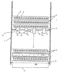
Figure 5 is a cross-sectional view of a section of a fractionation column 1
containing a pair of traditional cross-flow sieve trays 2. Liquid from above
flows
3 0 downward through a chordal downcomer formed by the wall 14 and curved
inner surface of
the column. The liquid impacts the imperforate receiving pan 35 and then ri-
avels
horizontally across the decking 31 of the tray. Vapor rises through the
perforations 15 in
11
CA 02353183 2001-07-13
the decking and causes vapor-liquid contact. The liquid then overflows the
outlet weir 13
and enters the inlet of the downcorner leading to the next lower tray. The
bottom tray
supports three sublayers of low surface area grid 3 while only a single layer
of grid 3 rests
upon the upper tray. In both instances, the grids 3 are oriented such that the
blades 8 run
from the receiving pan to the outlet weir. The blades are therefore aligned
with the general
direction of liquid and froth movement across the tray. The two upper
sublayers on the
bottom tray are aligned perpendicular- to lowest grid sublayer.
Figure 6a is an enlarged view looking sideways at a small portion of a
suitable low
surface area grid. Each grid is foamed by a large number, e.g., 20 to 40 or
more, individual
grid blades 8. The imperforate grid blades are held in a rigid position by a
number of grid
stringers 9 which extend through the grid 3. The grid stringers, which hold
the blades in
place, may simply fall into notches or they may be welded to each blade to
form a rigid
substantially inflexible structure. The overall gr7d bundles can theoretically
be formed as a
monolithic cylindrical pad-like structure approximately equal in size to the
internal
diameter of the fractionation column. However, it is much more feasible to
form smaller
grid bundles in the shape of rectangular sections about .3 to .5 meters wide
which are
placed on the trays or on supports extending across the column. The grid
bundles can be
fabricated to fit between the walls of adjacent downcomers and rest upon the
tray deck or
the top of the downcomers. The length of each grid bundle can be equal to the
width of the
2 0 column.
Figure 6b differs from Figure 6a in showing a grid structure formed from flat
blades
8 rather than the bent blades of Figure 6a. These blades would result in even
lower
pressure drop but are not as effective in increasing the capacity of the tray.
The blades of
this Figure have a number of rather large circular openings 29 spaced across
their face.
2 5 These openings are optional but will allow good froth admixture on the
tray and the
movement of froth through the blades.
The grid designs of Figure Ga and Gb share the common characteristic of having
relatively large vertical channels which allow unobstructed upward vapor flow.
Some grid
structures have angled portions of the blades which cross into the vertical
channels. The
3 0 width of the channels will be larger, typically larger than 3 cm, and the
channels more
unifor-rrr than in a structured packing. Portions of the blades themselves may
intersect or he
attached to each other at multiple points thereby eliminating the need for the
connecting
12
CA 02353183 2001-07-13
grid stringers 9.
Figures 7 and 8 illustrate ten different alternative structures (a) - (j) for
the blades 8
of the low surface area grid bundle. Many more are possible. In Figure 7 the
representati ve
blades 8 rest upon a horizontal support bar 27 which may be part of a
downcomer. In
Figure 8 the blades rest directly upon the upper surface of a section of
perforated tray
decking 5.
It is highly preferred that at least one portion of the blade structure is
inclined from
vertical such that one portion of the blade intercepts the rising vapor flow
and the other side
provides an inclined surface for increased liquid retention. This provides a
greater increase
in the capacity of the tray for a reason as yet unknown. The inclined straight
blade (h) is the
simplest example of such an inclined portion. The more complicated
bidirectional blades
(c) and (f) offer increased rigidity but at higher cost. There is no known
requirement for
sharp bends and it is believed the inclined surface can be provided by one or
more curves as
shown by blade (e). It is preferred that the blade is not shaped in a manner
which creates a
concave shape. The shape of blade (a) is therefore preferred over the shape of
blade (b).
The two low surface area grid blades 8 of Figure 8 differ from those of Figure
7 in
that each blade has one or more tabs (x, y, z) extending from the major
surface of the blade.
The tabs may protrude away from both sides of the blade as shown by tabs y and
z of blade
(j), which extend in opposite directions. The tabs can comprise separate
elements fastened
2 0 to the blades as by welding. However, it is preferred that the tabs are
formed by a
conventional metal forming procedure in which several cuts are made in the
blade and the
tab is formed by bending along the uncut metal at the base of the tab. This
operation will
form perforations in the blade. These perforations will conform in shape to
the tabs and
may augment other perforations in the blade.
Figure 9 illustrates a multiple downcomer type fractionation tray which may be
employed in the subject invention. The flat discoid tray 2 of Figure 9 has six
decking
sections 5, each of which has a large number of perforations 15 for the upward
passage of
vapor. This particular tray 2 is illustrated as having five rectangular
downcomers 12 evenly
spaced across the surface of the tray. The downcomers extend away from both
bottom and
3 0 top surfaces of the tray and are separated by strips of planar decking 5
intended for upward
vapor passage. All of the upward vapor flow in the column should pass through
the
perforations 15. Each downcomer borders two flat strips of decking. Each
downcomer has
13
CA 02353183 2001-07-13
a rectangular open upper end formed by the upward extension of the side and
end walls
upward beyond the decking surface. In a similar manner the downcomers extend
below the
tray, with the lower end of each downcomer being closed by a horizontal seal
plate having
liquid sealable perforations i7 for the passage of liquid. These perforations
17 of the tray
are sized to collectively allow the passage of the entire downward liquid flow
in the column
during operation while retaining sufficient liquid in the downcomers to
prevent upward
vapor flow.
Figure 10 illustrates a sectional side view of a single multiple downcomer
tray 2
similar to Figure 9 and comprising four parallel rectangular trough-like
downcomers 12
spaced across the tray. A flat decking section 5 is present on either side of
each
downcomer. The rectangular structure of the downcomers allows the side walls
32 to act as
beams providing vertical support for the decking sections. In this embodiment
the side
walls and end walls 33 are imperforate and all of the on-stream downward
liquid tlow
travels through the plurality of liquid sealable openings 17 provided in the
flat downcomer
seal plates 34. A single layer of low surface area grid 3 comprising the
substantially
vertical blades 8 and connecting stringers 9 rests directly upon the upper
surface of the
decking 5 of the tray between the downcomer sidewalls, which extend upward
beyond the
bottom portion of the grid. Vapor rising upward through the perforations 15
therefore
impinges upon the blades 8 of the grid.
2 0 Figure 11 is the view seen looking downward in a fractionation column 1
sectioned
above a c:rossflow fractionation tray 2. Liquid falling down a chordal
downcomer from the
next tray above falls upon the imperforate receiving pan 35 and proceeds
horizontatly
across the tray 2 towards the top of the Figure. Vapor from below rises
through the large
number of small diameter openings 15 evenly distributed across the decking 5.
For
2 5 simplicity these perforations 15 are shown only on a portion of the tray.
Upon reaching the
other side of the crossflow tray, the liquid flows over the outlet weir 13 and
downward into
a chordal downcomer leading to the next lower tray. This flow is similar to
that depicted in
Figures 3 and S.
A primary distinguishing characteristic of this apparatus is the provision of
3 0 differently angled low surface area grids 3 on the decking surface. The
grids are in several
flat bundles, with each grid bundle comprising a plurality of blades 8 and the
connecting
perpendicular stringers 9. The blades of different bundles are aligned in
different directions
14
CA 02353183 2001-07-13
as shown. These grids are shaped, placed and aligned such that vapor rising
from the grid
imparts a horizontal force to the froth on the tray, with this force tending
to cause the new
froth to diverge towards the sides of the tray. This is intended to reduce the
tendency of
liquid to stagnate in the side areas alongside the direct flow path from the
receiving pan 35
to the outlet weir 13. A second pair of angled grid bundles 3 located on the
outlet half of
the tray then speeds the collection of the froth from those areas and its
passage into the
outlet downcomer. These two sets of angled grids 3 are separated by an
intermediate
section of grids which are aligned parallel to the outlet weir 13. The angled
grid bundles
can differ in number from the four shown in the drawing and can be used on
only a smaller
portion of the tray. For instance, aligned grids located exclusively on the
inlet side of the
tray may be sufficient to promote the required froth movement. Additionally as
shown on
the drawing, sizable portions of the tray deck may be free of any grids. It
may be noted this
figure shows grid bundles of the same layer aligned in different directions,
as opposed to
prior figures in which sublayers were aligned in different directions.
The low surface area grid can be in the form of only a single layer or several
sublayers. The height of the grid is such that it does not fill the area
between vertically
adjacent trays. The percentage of the vertical distance between trays filled
by the grid
material will depend somewhat on tray spacing and will increase as tray
spacing is reduced.
It is preferred that between 10 to 75 percent of the space between trays is
filled with low
2 0 surface area grid. It is highly prefewed the low surface area grid fills
less than one-half the
space between the trays, with less than one-third of the space being filled
being highly
preferred.
The subject invention may be applied to multiple downcomer trays such as
described in the previously cited US-A- 3,410,540. Multiple downcomer trays
have several
2 5 distinguishing physical characteristics. For instance, a multiple
downcomer tray does not
have the receiving pan shown on the cross-flow trays discussed above. This is
the normally
imperforate section of tray deck located below the bottom of a downcomer. It
is therefore
the area of a tray upon which the liquid descending through the downcomer
impacts before
passing horizontally onto the perforated decking of the tray. Receiving pans
are normally
3 0 located directly below the downcomer leading from the next above
conventional
fractionation tray as shown in Figures 3, 5 and 11. The horizontal surface
area of a multiple
downcomer fractionation tray is divided into depressed areas functioning as
downcomer
CA 02353183 2001-07-13
means and flat vapor-liquid contacting area normally referred to as decking.
There are no
imperforate areas allocated to receiving descending liquid fiom the tray
located
immediately above.
Another distinguishing feature of a multiple downcomer type fractionation tray
is
the provision of a relatively large number of parallel downcomer means across
the tray.
Each tray can employ from one to fifteen or more downcomers. These downcomer
means
are spaced relatively close together compared to those of the more common
crossflow
fractionation trays as they are spread across the surface of the tray rather
than being at the
periphery of the tray. The distance between adjacent downcomers (measured
between their
side walls) of the same multiple downcomer tray will be between 0.2 and 1.0
meters and
preferably less than 0.5 meter. This results in a tray having a unique design
consisting of
the alternating decking areas and downcomer means evenly spaced across the
upper surface
of the fractionation tray, as shown in Figures 4, 9 and 10.
The structure of the downcomers of a multiple downcomer tray is also unique
compared to the downcomers employed upon crossflow fractionation trays. The
downcomer means do not extend downward to the next fractionation tray. Rather
they stop
at a much higher intermediate level located in the void volume between the two
trays. The
downcomer descending from the tray above therefore normally stops well above
the deck
surface of a lower tray and above the inlet to the downcomers of the tray
below. The inlet
2 0 to the downcomer of a tray functions as the outlet weir of the tray, and
the bottom of the
downcomer is preferably well above the outlet-weir of the lower tray. The
horizontal ends-
on cross-section of the downcomers can have a wide variety of shapes ranging
from
rectangular as in Figure 1 to triangular as in Figure 4.
A very distinctive feature of a multiple downcomer fractionation tray is the
2 5 provision of a liquid sealable means near the bottom of the downcomer. The
bottom of the
downcomer is partially closed off to retard the direct downward flow of liquid
out of the
downcomer. This causes the accumulation and retention of froth, which allows
it to
separate into clear liquid. The accumulated liquid seals the downcomer to the
upward flow
of vapor. This liquid sealable outlet is located well above the deck of the
tray located
3 0 immediately below. Preferably it is at a level above the inlet of the
downcomers associated
with this next lower tray. The clear liquid is collected in the lower portion
of the
downcomer and spills forth upon the next lower tray through the openings in
the bottom of
16
CA 02353183 2001-07-13
the downcomer. Some liquid may, if desired, exit through the openings in the
downcomer
side walls. The openings are grouped together and located such that the
exiting liquid does
not fall into a downcomer of the next lower tray.
In the embodiments employing V-shaped downcomers, the perforations 28 in the
downcomer side walls are preferably arranged in one or more rows running along
the major
axis of the downcomer. It is preferred that the holes are located in the side
walls rather than
along the bottom of the V-shaped downcomer. This helps impart horizontal
velocity to the
egressing liquid causing it to travel away from the downcomer. This is
beneficial in
spreading the liquid over any high surface packing 4 which is located below
the tray, hence
ensuring more uniform wetting of the packing. It is also useful in directing
the liquid onto
the decking areas of the tray below depending on the orientation and location
of the lower
tray decks. The perforations in the downcomer side walls are preferably
circular but could
have other shapes including horizontal or diagonal slots. The use of a smaller
number of
larger perforations is preferred although the perforations should be located
more or less
uniformly along the length of both side walls of the downcomer in a single row
to again aid
in spreading the liquid over the suspended high surface packing. Circular
openings of
about 0.5-2.5 centimeters diameter are suitable. An important facrnr ;n the
"IarPmP.,r "f
the downcomer perforations is the provision of an adequate distance between
the upper
surface of the tray, which may be coextensive with downcomer inlet, and the
perforations
2 0 to allow the entering froth to separate into clear liquid and vapor. This
is important to good
tray efficiency and performance in general. This distance should also provide
sufficient
liquid head to prevent the upward passage of vapor through the downcomer
perforations.
This desirable placement of the downcomer perforations can be characterized as
being in
the lower third of the downcomer sidewall.
2 5 The decking between any downcomers of a multiple downcomer type tray is
preferably substantially planar, that is flat, and orientated in a horizontal
plane. These
decking portions are provided with uniformly distributed openings of adequate
total cross-
sectional open area to allow the expected vapor flow to pass upward through
the tray at a
reasonable velocity. The uniform circular openings of a standard sieve tray
are preferred
3 0 but can be supplemented by vapor flow directing slots. The open area
provided by deck
perforations may be as high as 30-45% of the tray deck, as compared to a lower
area of up
to 20% normally used on ripple trays. The circular perforations may be up to
1.87 cm (.75
17
CA 02353183 2001-07-13
in) in diameter.
The apparatus according to the present invention can be in the form of a new
apparatus or as a modification to an existing apparatus. That is, an existing
trayed column
may be modified to employ the subject invention by placement of low surface
area grid on
some or all of the existing trays.
One embodiment of the invention may be characterized as a fractional
distillation
apparatus comprising a vertical enclosed column (1) having a circular cross
section and an
upper first end (20) and a lower second end (21); a pair of vertically spaced
apart multiple
downcomer fractionation trays (2) comprising a lower first tray and an upper
second tray,
with the trays extending across substantially a1.1 of the cross-sectional area
of the column
(1), and with the trays (2) having separate vapor passage decking sections (5)
and parallel
liquid collection downcomers (6, 12) distributed across the trays (2), with
the liquid
collection downcomers extending away from the tray (2) toward the second end
of the
column, and with perforations (28) for liquid passage being located in the
liquid collection
downcomers; and, a layer of low surface area structured grid packing (3 j
resting upon the
first tray of said pair of fractionation trays, with the layer of grid packing
extending toward
the second tray (2) for a distance equal to from about one-tenth to about
three-fourths of the
vertical distance between the first and second trays (2).
A further embodiment of the invention may be characterized as a fractional
distillation apparatus comprising a vertical enclosed column (1) having a
circular cross
section and an upper first end (20) and a lower second end (21 ); a pair of
vertically spaced
apart discoid fractionation trays (2) extending across substantially all of
the cross-sectional
area of the column (1), with the trays having separate substantially flat
perforated decking
sections (5) and liquid collection downcomers (6,12), which downcomers extend
away
from the tray (2) towards the lower second end of the column (1), and with
additional
perforations (17,28) for liquid passage being located in the liquid collection
downcomers; a
layer of low surface area structured grid packing (3) resting upon a lower
first tray (2) of
said pair of fractionation trays; and, a layer of high surface area packing
(4) located above
the layer of low surface area structured grid packing (3).
3 0 As previously mentioned an optional addition to the subject invention is a
bed of
high surface area packing. These optional beds are located between two trays
and
preferably do not contact either tray. As they receive the necessary liquid
from the next tray
~8
CA 02353183 2001-07-13
above their location is described as under the top tray. Tests have shown that
an effective
high surface area packing section need only be relatively thin, say 200 mm top
to bottom,
and so wall effects are insignificant. A minimum bed thickness of 10 cm is
desired, with
beds up to 150 cm thick being contemplated.
The amount of high surface area packing used with any one tray pair is
preferably
less than 50 percent of the volume of the column between the upper and lower
trays of the
pertinent tray pair. It is preferred that no high surface area packing
material is placed
directly on the surface of the trays. This allows conventional frothing and
liquid flow to
occur.
A bed of the optional high surface area packing provided in the column will
preferably be thicker, measured top to bottom, than the first layer of low
surface area grid
structure located below it. Any optional second layer of low surface area grid
structure
located above the bed of high surface area packing is preferably thinner than
the first
(lower) layer of low surface area grid structure. More precisely, it is
preferred that the first
(lower) layer is at least two times as thick, and more preferably at least
three times as thick
as the second (upper) layer of low surface area grid packing.
The optional packing beds may contain any of the many known random packings;
e.g., sings, spheres, saddles, or structured (ordered) bed packings; e.g.,
corrugated, rolled,
screens or plates. Examples of random and structured packings are provided in
LJ.S.
2 0 Patents 5,200,119 and 5,132,056.
The high surface area packing beds may be suspended by a porous woven wire
screen. The screen itself may be held in place in a number of ways. The screen
may rest on
a grid bundle or a plurality of support bars which crisscross the internal
volume of the
column in a plane parallel to the trays. The screen or the individual packing
elements may
2 5 alternatively be suspended (hung) from the tray above. These mechanical
details may be
varied to suit individual situations and are not deemed a limitation on the
inventive
concept.
Some embodiments of the invention include an element which functions to supply
liquid to the optional high surface packing bed. Openings in the decking
material may be
3 0 used for this purpose in addition to allowing vapor flow. Some portion;
e.g., 25-40 vol.~7~
of the liquid flowing across the tray deck S, may therefore flow downward
through
openings in the deck to allow liquid to flow onto the packing 4. Those skilled
in the art
19
CA 02353183 2001-07-13
will recognize there are a number of ways to distribute liquid from the tray
to the packing.
It is preferred to avoid the use of any mechanically complex system involving
conduits,
pipes and valves, inclined troughs, etc. The liquid which is spread across the
packing may
be derived from a downcomer, a separate liquid collection area or from the
tray deck itself.
For these purposes it is preferred to utilize some form of "dual flow" tray
decking. That is.
the tray intentionally allows liquid to "weep" downward as by having some
larger diameter
holes or devices to promote liquid flow through the holes. Valuing means known
to the art
may also be placed on the tray to regulate liquid and vapor flow and to
accommodate
variations in these flows due to changes in feed or reflux rates in the
column.
The trays of the subject invention are fractionation trays as compared to
liquid
distributors found in packed columns. Some characteristics of fractionation
trays include a
much closer vertical spacing than for redistributors; a design which causes
intimate,
vigorous contact of liquid retained on the tray with vapor passing upward
through the tray
and the formation of froth on the surface of fractionation trays; and an
abundance of closely
spaced perforations across a high percentage of the decking area of the
fractionation trays.
On a fractionation tray, a large percentage, approximately 70°70, of
the tray's cross-sectional
area is comprised of decking. The conventional redistributors of packed
columns employ
no decking. On a tray, mass transfer, that is, purification or separation
occurs; on a
conventional redistributor, no mass transfer occurs.