Language selection

Search

Patent 2353372 Summary

Third-party information liability

Some of the information on this Web page has been provided by external sources. The Government of Canada is not responsible for the accuracy, reliability or currency of the information supplied by external sources. Users wishing to rely upon this information should consult directly with the source of the information. Content provided by external sources is not subject to official languages, privacy and accessibility requirements.

Claims and Abstract availability

Any discrepancies in the text and image of the Claims and Abstract are due to differing posting times. Text of the Claims and Abstract are posted:

  • At the time the application is open to public inspection;
  • At the time of issue of the patent (grant).
(12) Patent Application: (11) CA 2353372
(54) English Title: FLUID COLLECTOR ASSEMBLY
(54) French Title: ASSEMBLAGE DE COLLECTEUR DE FLUIDE
Status: Dead
Bibliographic Data
(51) International Patent Classification (IPC):
  • A61M 5/32 (2006.01)
  • A61M 25/06 (2006.01)
(72) Inventors :
  • GARVIN, DAVID M. (United States of America)
(73) Owners :
  • RETRAX SAFETY SYSTEMS, INC. (United States of America)
(71) Applicants :
  • RETRAX SAFETY SYSTEMS, INC. (United States of America)
(74) Agent: FINLAYSON & SINGLEHURST
(74) Associate agent:
(45) Issued:
(22) Filed Date: 2001-07-23
(41) Open to Public Inspection: 2002-01-21
Examination requested: 2006-07-24
Availability of licence: N/A
(25) Language of filing: English

Patent Cooperation Treaty (PCT): No

(30) Application Priority Data:
Application No. Country/Territory Date
09/620,929 United States of America 2000-07-21

Abstracts

English Abstract


The present invention relates to a fluid collection method and assembly in
which the
needle is retracted inside the syringe after the sample is taken. A standard
sealed blood
collection tube is inserted into the outer barrel of the syringe. A double
ended needle held by
the syringe has one end inserted into the patient and the other end through
the seal of the
blood collection tube. After the blood collection tube is removed, the user
inserts a plunger
into the cavity between an inner and outer barrel which initiates an automatic
retraction of the
needle into the assembly device. In operation, a collet is expanded and a
spring biased needle
retractor is engaged in response to the forward movement of the plunger. The
forward end of
the barrel carries a wedge which force the collet to expand upon forward
movement of the
collet.


Claims

Note: Claims are shown in the official language in which they were submitted.


8
WHAT IS CLAIMED IS:

1. An assembly for use with a blood collection tube, said blood collection
tube having a
closed end and an open end sealed by an elastomeric material, said assembly
comprising a tube
holder with an outer barrel for slidably receiving the blood collection tube,
said outer barrel
having a forward end and rearward end, said forward end of said outer barrel
having an
opening, an inner barrel having a forward end and an open rearward end
slidably inserted into
the rearward end of said outer barrel, said inner barrel having an expandable
collet mounted on
said forward end thereof, spring means positioned between said outer barrel
and inner barrel
so as to bias said inner barrel rearwardly with respect to said outer barrel,
said collet extending
through said forward end of said outer barrel opening and engaging said
opening in said
forward end of said outer barrel, said opening constricting said collet as
said callet is biased
rearwardly through said opening, a needle retractor having a forward end
extending through
said collet and adapted to receive a needle slidably received in said inner
barrel, said needle
retractor having a shoulder trap engaging said restricted collet, said needle
retractor having a
tubular body and a rearward end carrying a puncture means for penetrating the
elastomeric
seal of said blood collection tube, second spring means for biasing said
needle retractor
rearwardly positioned between said inner barrel and said needle retractor, and
a tubular
plunger having an annular forward end and a rearward end, said plunger adapted
for insertion
into the rearward end of said outer barrel, said annular forward end of said
plunger adapted to
contact said inner barrel whereby forward movement of said inner barrel with
respect to said
outer barrel releases said needle retractor element rearwardly into said inner
barrel.

2. An assembly as in claim 1 further comprising a vent in said rearward end
portion of
said plunger.


9

3. An assembly as in claim 2 further comprising a needle connected to the
forward
end of said needle retractor element.

4. An assembly as in claim 2 further comprising screw attachment means for
attaching said needle to a forward end of said needle retractor.

5. An assembly as in claim 2 wherein said spring means comprises a coil
spring.

6. An assembly as in claim 2 wherein said second spring means comprises a coil
spring.

7. An assembly as in claim 2 wherein said forward end of said inner barrel is
enlarged
to form a first seal between said outer barrel portion and said inner barrel.

8. An assembly as in claim 7 wherein said first seal means comprises a
separate O-ring
type seal mounted on said forward end of said inner barrel.

9. An assembly as in claim 2 wherein said expandable collet has a funnel
shaped
exterior and includes slats which enable expansion in contraction of the
longitudinal
passageway located within said collet.

10. An assembly as in claim 9 wherein said opening in said forward end of said
outer
barrel has at least one wedge element, said wedge element engaging said slots
in said collet to
force sand collet to expand.


10

11. An assembly as in claim 2 wherein said outer barrel and said plunger are
connected with a tether, said tether connecting said rearward end of said
outer barrel said
rearward end or said plunger.

12. An assembly as in claim 2 with means within said inner barrel for guiding
and
supporting the blood collection tube.

13. A method for collecting fluid samples comprising:

A) providing a blood collection tube having a closed end and an open end
sealed with an
elastomeric material;

B) providing an assembly having a tube holder with an outer barrel for
slidably receiving
the blood collection tube, said outer barrel having a forward end and a
rearward end, said
forward end formed with an opening therein, an inner barrel having a forward
end and an open
rearward end slidably inserted into the rearward end of said outer barrel,
said inner barrel
having an expandable collet mounted on said forward end thereof, spring means
positioned
between said outer barrel and inner barrel so as to bias said inner barrel
rearwardly with
respect to said outer barrel, said collet extending through said forward end
of said outer barrel
opening and engaging said opening in said outer barrel, said opening
constricting said collet
as said collet is biased rearwardly through said opening, an elongated needle
retractor having a
through bore slidably extending through said collet and said inner barrel, one
end of said
needle retractor adapted to receive a needle, said needle retractor having a
shoulder trap
engaging said restricted collet, said needle retractor having a puncture means
for penetrating
said elastomeric seal of said blood collection tube on the other end, a second
spring biasing
said needle retractor rearwardly positioned between said inner barrel and said
needle retractor,


11

and a tubular plunger having an annular forward end and a rearward end,; and
C) inserting said needle into a patient, inserting said open end of said blood
collection tube
into said outer barrel, penetrating said elastomeric seal with said puncture
means, collecting
said sample in said blood collection tube, removing said blood collection tube
from said outer
barrel, inserting said plunger in said outer barrel, advancing said annular
forward end of said
plunger over said inner barrel into contact with said forward end of said
inner barrel,
continuing advancing said plunger compressing said spring means and expanding
said collet
out of contact with said shoulder trap, said needle retractor sliding into
said inner barrel in
response to the bias of said second spring means carrying said needle within
said needle holder
Description

Note: Descriptions are shown in the official language in which they were submitted.


CA 02353372 2001-07-23
1
1 FLUID COLLECTOR ASSEMBLY
2
3 FIELD OF THE INVENTION
4 This invention relates generally to the collection of blood samples and more
specifically
to a method and an assembly for collecting fluid samples with a retractable
needle and fluid
6 collecting tube holding device which following the stroke of the plunger,
automatically retracts
7 the needle into the body of the assembly.
8
9 BACKGROUND OF TIC I7VVENTION
I O Blood samples and other medical specimens are routinely taken and
collected in a
11 specimen collection container. The typical blood collection container is a
hollow blood
12 collection tube with one end closed by a semi-spherical portion and the
other end open. The
13 open end is sealable by an impervious elastomeric cover.
14 To collect a blood sample, the tube is used in concert with a tube holding
device.
1 S Normally the holding device has a hollow needle extending through the
closed end of a tubular
16 housing. The tubular housing has an opposed open end for accepting the
blood collection
17 tube. The hollow needle is inserted through the dermal layer into the lumen
of the blood
18 vessel into the circulation system of a subject to direct blood there
through towards the
19 interior compartment of the holding device. The collection container is
inserted through the
20 open end of the holder so that the hollow needle punctures through the
elastomeric cover of
21 the collection container. The interior of the collection container is now
in direct
22 communication with the circulation system and, having typicalLly been
formed in a vacuum,
23 draws blood through the hollow needle and into the collection container.
Once enough blood
24 has been drawn, the container may be removed from the holder.


CA 02353372 2001-07-23
2
I The tube holding device with its contaminated needle presents the danger of
an
2 accidental needle stick. Even trace amounts of body fluids from a person
with Hepatitis,
3 Acquired Immune Deficiency Syndrome (AIDS) etc. transferred into another's
blood stream
4 can transmit these diseases. Thus, what is needed in the art is a fluid
collecting tube holding
device that protects from inadvertent needle sticks.
6
7 SC~I~llViARY OF THE 1NVENTION
8 Thus, an object of the instant invention is to provide a iduid collecting
tube holder that
9 causes the contaminated hypodermic syringe to retract into the: holder, by
insertion of a
plunger, so that the needle is enclosed within the holder.
i 1 It is a further object of the instant invention to provide a plunger
device that is either
12 unattached or attached to the fluid colleting tube device holder such that
it does not interfere
13 with the collection of the fluid sample but is easily accessible f«r
insertion into the tube holding
14 device.
Another object of the instant invention is to provide a <;ollet which expands
and
16 releases a spring biased needle retractor in response to the fonward
movement of the plunger.
17 The forward end of the outer barrel carries a wedge which insures the
collet fingers will spread
18 apart upon forward movement of the collet.
19 It is yet another object of the instant invention to provide a vent in the
plunger. The
vent allows air to escape from the interior of the plunger as the needle
assembly is retracted by
21 or in response to spring action.
22 It is still another object of the instant invention is to provide an
inexpensive, easily
23 manufactured and used tube holding device with a retractable needle
mechanism for safe
24 disposal and prevention of diseases

CA 02353372 2001-07-23
3
1 It is further objective of the instant invention to provide a method for
collecting fluid
2 samples that significantly reduces accidental needle sticks.
3 Other objectives and advantages of this invention will become apparent from
the
4 following description taken in conjunction with the accompanying drawings
wherein are set
forth, by way of illustration and example, certain embodiments, of this
invention. The
6 drawings constitute a part of this specification and include exemplary
embodiments of the
7 present invention and illustrate objects and features thereof.
8
9 BRIEF DESCRIPTION OF THE DRAW1NGS
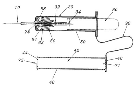
I O Fig. 1 is a partial sectional view of the fluid collection ;assembly;
I 1 Fig. 2 is a partial sectional side view of the fluid collection assembly
with the plunger in
12 the forward position, a screw mounted needle according to the present
invention is shown;
13 Fig. 3 is a partial sectional side view of the fluid collection assembly
according to the
14 presem invention shown in the retracted position;
I 5 Fig. 4 is an exploded view of the fluid collection asserr~bly sequence of
the component
16 parts with the forward end of the barrel enlarged;
17 Fig. 5 is an enlarged partial sectional view of the forty<~rd end of the
assembly
18 according to the present invention;
I9 Fig. 6 is an end view of the expanding collet used in tlhe present
invention;
20 Fig. 7 is a plan view of the collet and inner barrel; andl
21 Fig. 8 is a cross-sectional view of the collet and inner barrel.
22
23 DETAILED DESCRIPTION
24 As shown in Figs. I-5, the invention is a combination of a fluid collection
tube holding


CA 02353372 2001-07-23
4
1 device 20 and a needle 10. The device features a separately attached needle
hub including a
2 metal cannula 12 and a threaded attachment portion I4.
3 The fluid collection tube holding device 20 includes a hollow inner barrel
60 which
4 cooperates with a needle retractor 30 to draw the needle 10 into the inner
barrel following use
of the needle. This action is accomplished by inserting the plunger 40 into
the hollow space
6 between the inner barrel 60 and outer barrel S0. The continued stroke of the
plunger 40 moves
7 collet 66 forward and releases needle retractor 30 which is then propelled
by spring action into
8 the body of the plunger.
9 The fluid collection tube holding device 20 is made up of an outer barrel or
tube SO
and an inner barrel 60. The inner barrel has a forward end 64 which has an
additional seal
I 1 element 62, p-ring in this embodiment, which seals the inner barrel to the
inner surface of the
I2 outer barrel S0. Between the inner barrel 60 and the outer barrel 50 is a
space into which the
I3 plunger 40 is introduced from the rear end of the syringe. The plunger 40
has a tubular body
14 42 and an annular plunger end 44 with a central aperture 75 on a forward
end of the plunger.
Aperture 75 is sized to accommodate the inner barrel 60. The annular plunger
end 44 is sized
16 to form liquid proof contact with the outer barrel. At the rear end of the
plunger a push
17 element 46 can be provided to engage the user's thumb. A vent 7I is formed
in the rear end of
18 the plunger adjacent to push element 46. The vent 71 permits outward flow
of air from the
I9 interior of the plunger when the needle 10 and retractor 30 are; retracted
into the plunger.
The forward end 64 of the inner barrel 60 also include:> a collet 66 which
acts as a
21 movable stop between the outer barrel and the needle retractor. The collet
has slots 67 in the
22 external funnel shape which creates a contracting and clamping effect for
the collet as it is
23 withdrawn through the opening 72 located at the forward end of the outer
barrel 50. The
24 collet is biased into a clamping or retracted position by a shore: spring
68 which biases the inner


CA 02353372 2001-07-23
1 barrel 60 rearwardly with respect to the outer barrel 50.
2 The holder 30 is adapted to be inserted through the tubular body of the
inner barrel 60
3 from a rearward end thereof. The retracting holder 30 includes a fluid
expelling portion 32
4 with a puncture end 34 capable of puncturing the elastomeric end of the
specimen tube 80 and
expelling the fluid into the specimen tube 80. The retracting holder 30 passes
fluid from the
6 vein through the needlel0 and the fluid expelling portion 32 into the
specimen tube 80 . The
7 specimen tube can be removed and another used to allow for multiple samples
to be taken
8 from one site.
9 Details of the collet 66 of this embodiment are shown i:n Figs 6, 7 and 8.
The collet
includes a plurality of slots 67 which allow for expansion and contraction of
the collet as the
I I exterior funnel shape of the collet is urged forwardly and rearwardly
through the forward
12 opening 72 in outer tube 50 of the fluid collection tube holding; device
20. The slats 67 are
13 larger at the forward ends 73 of the collet and taper rearwardly. The
forward ends 73 of the
I4 slots 67 are sized to accommodate the wedges 74. When the c;ollet 66 is
urged rearwardly
IS with respect to the outer barrel 50 by a short spring 68, the slots 67 in
the collet forward end
16 are forced into a closed position, without interference from wedges 74,
reducing the diameter
17 of the collet and clamping the holder 30. This clamping and retention of
the holder is helped
18 by the trapped edge 31 which is present of the exterior of the holder 30.
The collet 66 clamps
19 onto the holder just behind the trapped edge. The trapped edge 3 I is shown
as an annular
element in this embodiment, however, it can take on any shape; which binds
against the
21 restricting edges of the collea 66 and retains the holder 30 in the forward
end of the inner
22 barre160.
23 The retracting holder 30 is biased rearwardly by long spring 38 which
pushes on the
24 erid cap 34 of the holder. To release the holder 30, the collet 66 is
expanded by forward


CA 02353372 2001-07-23
6
1 movement of the collet 66 in response to contact with the inner barrel
forward end 64, and the
2 forward end 44 of the plunger. The forward movement of the r;,ollet 66 frees
the collet from
3 the constriction of the opening 72 and engages the narrowed portions 75 of
the slots 67 with
4 the wedges 74 to force the collet to expand clear of the lip on 'the
retracting holder 30.
To collect a sample, the user inserts the needle 10 of the assembly into a
vein. The
6 elastomeric end of the specimen tube 80 is introduced into the rearward end
of the inner barrel
7 60. The specimen tube 80 is fully inserted into the inner barrel 60 until
the puncture end 34 of
8 the fluid expelling portion 32 punctures the elastomeric end of the specimen
tube 80. The
9 blood enters the needle 10 of the retracting holder 30 through the fluid
expelling portion 32
and into the specimen tube 80. After the user has collected the quantity
needed, the specimen
I I tube 80 is removed from the inner barrel 60. Another specimen tube can be
inserted if
12 multiple samples are needed.
23 When the user has removed the specimen tube, the plunger 40 is inserted
into the
14 space between the inner barrel 60 and outer barrel 50. The user pushes
until the annular
plunger end 44 urges against the inner barrel 60 which in turn pushes the
collet 66 forward.
16 By pushing forward, the collet 66 expands and the holder 30 disengages from
the collet 66 and
17 the holder 30 is propelled rearwardly into the tubular body of the inner
barrel 60. The needle
18 10 is then disabled with the needle trapped within the assembly as shown in
Fig. 3. The
19 plunger 40 can be connected to the outer barrel 50 by a tether 80 placed on
the rearward ends
of each. This prevents misplacement of the plunger.
21 The assembly sequence of the present invention is shown in Fig. 4. The
holder 30 and
22 the associated long spring 38 are inserted into the inner barrel 60 which
is comprised of a
23 forward end 64 and seal 62 and collet 66. The inner barrel 60 and the short
spring 68 are
24 loaded into the outer tube 50 followed by the insertion of the .assembled
holder 30. The holder

i;
CA 02353372 2001-07-23
7
1 is inserted until engagement of the collet occurs forward followed by the
insertion of the
2 assembled plunger. The entire assembly includes four polymer plastic molded
parts, namely
3 the plunger, outer and inner barrels, the holder and seal, and taro springs.
The seal can also be
4 a polymer and consequently be molded together with the respective inner
barrel and holder as
desired. By virtue of the comparatively few numbers of parts ~~nd their
simplicity in execution,
6 the present assembly and retractable needle combination can bf; readily and
economically
7 manufactured.
8 It is to be understood that while I have illustrated and described certain
forms of my
9 invention, it is not to be limited to the specific forms or arrangE;ment of
parts herein described
and shown. It will be apparent to those skilled in the art that various
changes may be made
1 I without departing from the scope of the invention and the invention is not
to be considered
I2 limited to what is shown in the drawings and described in the
specification.
13
14

Representative Drawing
A single figure which represents the drawing illustrating the invention.
Administrative Status

For a clearer understanding of the status of the application/patent presented on this page, the site Disclaimer , as well as the definitions for Patent , Administrative Status , Maintenance Fee  and Payment History  should be consulted.

Administrative Status

Title Date
Forecasted Issue Date Unavailable
(22) Filed 2001-07-23
(41) Open to Public Inspection 2002-01-21
Examination Requested 2006-07-24
Dead Application 2009-07-23

Abandonment History

Abandonment Date Reason Reinstatement Date
2008-07-23 FAILURE TO PAY APPLICATION MAINTENANCE FEE

Payment History

Fee Type Anniversary Year Due Date Amount Paid Paid Date
Registration of a document - section 124 $100.00 2001-07-23
Application Fee $150.00 2001-07-23
Maintenance Fee - Application - New Act 2 2003-07-23 $50.00 2003-07-22
Maintenance Fee - Application - New Act 3 2004-07-23 $50.00 2004-07-23
Maintenance Fee - Application - New Act 4 2005-07-25 $50.00 2005-07-14
Request for Examination $400.00 2006-07-24
Maintenance Fee - Application - New Act 5 2006-07-24 $100.00 2006-07-24
Maintenance Fee - Application - New Act 6 2007-07-23 $100.00 2007-07-23
Owners on Record

Note: Records showing the ownership history in alphabetical order.

Current Owners on Record
RETRAX SAFETY SYSTEMS, INC.
Past Owners on Record
GARVIN, DAVID M.
Past Owners that do not appear in the "Owners on Record" listing will appear in other documentation within the application.
Documents

To view selected files, please enter reCAPTCHA code :


To view images, click a link in the Document Description column. To download the documents, select one or more checkboxes in the first column and then click the "Download Selected in PDF format (Zip Archive)" or the "Download Selected as Single PDF" button.

List of published and non-published patent-specific documents on the CPD .

If you have any difficulty accessing content, you can call the Client Service Centre at 1-866-997-1936 or send them an e-mail at CIPO Client Service Centre.


Document
Description 
Date
(yyyy-mm-dd) 
Number of pages   Size of Image (KB) 
Claims 2001-07-23 4 168
Abstract 2001-07-23 1 26
Description 2001-07-23 7 348
Representative Drawing 2001-12-28 1 11
Drawings 2001-07-23 7 222
Drawings 2001-10-22 7 148
Cover Page 2002-01-21 1 42
Correspondence 2001-08-10 1 18
Assignment 2001-07-23 8 370
Correspondence 2001-10-22 16 406
Fees 2003-07-22 1 26
Prosecution-Amendment 2006-07-24 1 34
Correspondence 2007-09-11 2 49