Note: Descriptions are shown in the official language in which they were submitted.
CA 02353426 2001-07-23
;'i
A METHOD AND SYSTEM FOR TURBO El'JCODING IN ADSL
The invention relates to the field of asynchronous digital subscriber line
("ADSL"}
communication systems. More specifically, the invention :relates to a system
and method
for encoding signals applied to ADSL.
BACKGROUND OF THE INVENTION
Channel coding methods are used in order to design reliable digital
communication
systems. Although channel coding improves error performance through the
mapping of
input sequences into code sequences, this adds redundancy and memory to the
transmission. Shannon's Theorem holds that small error rates are achievable
provided
that the rate of transmission is less than the capacity of the channel.
In the early 1990s, a very powerful channel coding scheme was developed which
used
concepts related to block and trellis codes. The encoding scheme used simple
convolutional codes separated by interleaving stages to produce generally low
rate block
codes. Decoding was performed by decoding the convoluti.onal encoders
separately using
a "soft" output Viterbi algorithm and sharing bit reliability information in
an iterative
manner. This new coding scheme was called "Turbo Coding" and it was found to
be
capable of near Shannon capacity performance as described in C. Berrou, and A.
Glavieux, "Near Optimum Error Correcting Coding And L>ecoding: Turbo-Codes",
IEEE
Trans. Commun., vol. COM-44, No. 10, October 1996, pp.1261-1271.
In general, a turbo encoder is a combination of two simple; encoders where the
input is a
block of lVL information bits. The two encoders generate; parity symbols using
simple
recursive convolutional encoders each with a small numlber of states. The
information
bits are also transmitted uncoded. A key innovation of turbo encoders was the
use of an
interleaver which permutes the original M information bits before input to the
second
encoder. The permutation is generally such that input ;>equences for which the
first
encoder produces low-weight code-words will typically cause the second encoder
to
produce high-weigh code-words. Thus, even though the constituent codes may be
individually weak, the combination code is powerful. 'This resulting code has
features that
1
CA 02353426 2001-07-23
are similar to a random block code with M information lbits. Random block
codes are
known to achieve Shannon-limit performance as M increases but with a
corresponding
increase in decoder complexity.
Turbo codes may achieve the performance of random codes (for large M) using an
interative decoding algorithm based on simple decoders that are individually
matched to
the constituent codes. In a typical turbo decoder, each constituent decoder
generally sends
a posteriori likelihood estimates of the decoded bits to th.e second decoder
and uses the
corresponding estimates from the second decoder as a priori likelihood
estimates. The
decoders generally use the maximum a posteriori ("MAF"') bitwise decoding
algorithm
which requires the same number of states as the well-knovm Viterbi algorithm.
The turbo
decoder iterates between the outputs of the two constituent decoders until
reaching
satisfactory convergence. The final output is a "hard" quantized version of
the likelihood
estimates of either of the decoders.
As turbo codes have a near Shannon limit, error correcting performance, they
are of
potential use in a wide range of telecommunications applications. As
mentioned, turbo
codes were originally proposed for binary modulation using two binary
convolutional
component codes separated by an interleaver. For moderate QAM (quadrature
amplitude
modulation) constellation modulation, bit-level turbo coded QAM and symbol-
level turbo
TCM (trellis coded modulation) have been proposed as described in P.
Robertson, and T.
Worz, "Bandwidth-Efficient Turbo Trellis-Coded Nl'odulation Using Punctured
Component Codes", IEEE J-SAC, vo1.16, No.2, Feb., 1998, pp.206-218; S. L.
Goff, A.
Glavieux, and C. Berrou, "Turbo-Codes and High Spectral Efficiency
Modulation", IEEE
ICC94; pp. 645-649, 1994; and, "New Proposal of Turbo Codes for ADSL Modems",
ITU
Standard Contribution, Study Group 15/4, BA-02081, Antwerp, Belgium, June. 19-
23,
2000.
Typically, bit-level turbo coded QAM combines the binary turbo codes with
large
constellation modulation using Gray mapping whereas symbol-level turbo TCM
uses
TCM codes as component codes that are separated by a symbol-level interleaver.
2
--_.#~.. --~- -_
CA 02353426 2001-07-23
A problem arises in the deployment of turbo codes in ADSL (asynchronous
digital
subscriber line) communication systems where these codes are combined with
very large
modulation constellations. These constellations may be as large as 215=32768
QAM
symbols. For conventional bit-level turbo coded QAM using Gray mapping, the de-
mapper, which calculates the soft information bits from the received
constellation signal,
requires an excessive number of computations. In addition, the turbo decoder's
complexity (i.e. length) is proportional to the number of bits transmitted in
one
constellation symbol. Therefore, the overall receiver becomes very
complicated. For
symbol-level turbo TCM using two-dimensional or four-dimensional set
partitioning
mapping, the turbo decoder's length is independent of the; number of bits
transmitted in
one constellation symbol, but its de-mapper still requires and excessive
number of
computations. Furthermore, the decoder uses a much more complicated symbol MAP
decoder. Consequently, the very large constellation size used in ADSL systems
makes
both conventional bit-level turbo coded QAM and symbol-level turbo TCM very
1 S complicated to decode at the receiver end. In other words, conventional
bit-level turbo
coded QAM and symbol-level turbo TCM both have very high decoding complexity
for
large ADSL related constellations. These techniques are described in S.
Benedetto, D.
Divsalar, G. Montorsi, and F. Pollara, "Paralell Concatenated Trellis Coded
Modulation", IEEE ICC96, 1996, pp.974-978; L. Bahl, J. Cocke, F. Jelinek, and
J. Raviv,
"Optimum Decoding of Linea~° Codes for Minimizing Symbol Error Rate",
IEEE Trans.
Inform. Theory, vol. IT-20, pp. 284-287, Mar. 1974; J. Hagenauer and P.
Hoeher, "A
Vite~bi Algorithm with Soft-Decision Outputs an:d Its Application", IEEE
GLOBECOM89, pp.47.1.1-47.1.7, Nov. 1989; D. Divsalar, "Turbo Codes for PCS
Applications", IEEE ICC95, pp. 54-59, 1996; P. Robertson, "Illuminating the
Structure of
Parallel Concatenated Recursive Systematic (TURBO) Codes", IEEE GLOBECOM94,
pp. 1298-1303, Nov. 1994; S. Benedetto, D. Divsalar, G. Montorsi, and F.
Pollara,
"Parallel Concatenated Trellis Coded Modulation", IEEE ICC96, 1996, pp.974-
978; and,
G. Ungerboeck, "Channel Coding with MultilevellPhase Signals", IEEE traps.,
Inform.
Theory, vol. IT-28, No. l, January 1982, pp.55-67.
A need therefore exists for a method and system that will. allow for the
effective use of
turbo coding in ADSL communication systems.
3
CA 02353426 2001-07-23
SUMMARY OF THE INVENTION
In accordance with this invention there is provided a method for the encoding
sequence
of information bits in a digital signal. The method comprises the steps of
dividing the
information bits into encoding bits and parallel bits; encoding the encoding
bits to
5 produce encoded bits; mapping the encoded bits and the p<~rallel bits into
first and second
PAM signals; and generating a QAM signal from these first and second PAM
signals.
According to another aspect of the invention there is provided a coding system
monitoring data representing sequences of instructions which when executed
cause the
above-described method to be performed. The coding system generally includes
parallel-
to-serial transfer means, interleaver means, encoder means, puncturing means,
mapper
means, and mode control means.
BRIEF DESCRIPTION OF THE DRAWINGS
The invention may best be understood by referring to the following description
and
accompanying drawings which illustrate the invention. In the drawings:
FIG. 1 is a block diagram of a turbo coding system in accordance with a
preferred
embodiment of the invention;
FIGS. 2 (a), (b) and (c) are line diagrams illustrating a concatenated gray
mapping for an
4-ASK, 8-ASK, and 16-ASK respectively in accordance with a preferred
embodiment of
the invention;
FIG. 3 is a block diagram of a turbo coding system with coding rate 2m/(2m+2),
where
m>0, in accordance with one embodiment of the invention;
FIG. 4 is a block diagram of a turbo coding system with coding rate
(2m+1)/(2m+2),
where m>0, in accordance with another embodiment of the. invention;
4
.--..-..,..,..-,~.F.. , a:a....m.~.,a:3 ~......a. r,~:,gRrpqy2,,p,.~y~p~p. ..
. .... -__.--
CA 02353426 2001-07-23
a v
FIG. 5 is a block diagram of a universal turbo coding system using mode
control with
coding rates 2m/(2m+2) and (2m+1 )/(2m+2), where m>0, in accordance with the
invention;
FIG. 6 is a block diagram of a general turbo coding system using an arbitrary
turbo
coding method with coding rate 2m/(2m+2), where rn>0, in accordance with one
embodiment of the invention;
FIG. 7 is a block diagram of a general turbo coding system using any turbo
coding
method with coding rate (2m+1)/(2m+2), where m>0,, in accordance with another
embodiment of the invention;
FIG. 8 is a block diagram of a universal turbo coding system similar to the
embodiment
of figure 5 using mode control and any turbo coding method with coding rates
2m/(2m+2) and (2m+1 )/(2m+2), where m>0;
FIG. 9 is a block diagram of a turbo product or low-density parity check
coding system
with coding rate 2m/(2m+2), where m>0, in accordance with a preferred
embodiment;
FIG. 10 is a block diagram of a turbo product or low-density parity check
coding system
with coding rate (2m+1)/(2m+2), where m>0, in accordance with a preferred
embodiment;
FIG. 11 is a block diagram of a universal turbo product or low-density parity
check
coding system using mode control with coding rates 2n~/(2m+2) and
(2m+1)/(2m+2),
where m>0, in accordance with a preferred embodiment;
FIG. 12 is a block diagram of a turbo coding system with coding rate
2m/(2m+2), where
m>0, where the six least significant bits are encoded by turbo codes, and
where the
puncturing rate is 3/, in accordance with a preferred embodiment;
FIG. 13 is a block diagram of a turbo coding system with coding rate
(2m+1)/(2m+2),
where m>0, where the six least significant bits are encodedl by turbo codes,
and where the
puncturing rate is 9/10 in accordance with a preferred embodiment;
5
CA 02353426 2001-07-23
Y
FIG. 14 is a block diagram of a bit level turbo TCM system in accordance with
the prior
art;
FIG. 15 is a block diagram of a turbo TCM encoder system with coding rate
R=1/2 for
4QAM or a group of two 2QAM in accordance with a preferred embodiment;
FIG. 16 is a block diagram of a turbo TCM encoder system with coding rate
R=(2+2m)/(4+2m) for MQAM, where M> 16 and M=2m, in accordance with a preferred
embodiment;
FIG. 17 is a block diagram of a turbo TCM encoder system with coding rate
R=(3+2m)/(4+2m) for MQAM, where M>16 and M=2m;
FIG. 18 is a block diagram of a universal turbo TCM encoder system MQAM in
accordance with a preferred embodiment;
FIG. 19 is a block diagram of a symbol level turbo TCM system in accordance
with the
prior art; and,
FIG. 20 is a block diagram of a turbo TCM encoder system for small
constellation sizes
in accordance with a preferred embodiment.
DETAILED DESCRIPTION OF THE PREFERRED EME~ODIMENTS
In the following description, numerous specific details are set forth to
provide a thorough
understanding of the invention. However, it is understood that the invention
may be
practiced without these specific details. In other instances, well-known
software, circuits,
structures and techniques have not been described or shown in detail in order
not to
obscure the invention. In the drawings, like numerals refer to like structures
or processes.
The term asymmetric digital subscriber line ("ADSL") is used herein to refer
to a
technology for transmitting digital information which simultaneously
transports high-bit-
6
CA 02353426 2001-07-23
rate digital information downstream to a subscriber or customer, lower-bit-
rate data
upstream from the subscriber, and analog voice typically via a twisted-wire-
pair.
The term amplitude shift keying ("ASK") is used herein to refer to a
modulation
technique that uses one signal of constant frequency, but varies the strength
of the signal
according to the state of the digital information to be conveyed.
The term binary phase shift keying ("BPSK") is used herein to refer to a
modulation
technique wherein the phase of the RF carrier is shifted 1 f~0 degrees in
accordance with a
digital bit stream.
The term discrete mufti-tone ("DMT") is used herein to refer to a multicarrier
transmission technique that uses a Fast Fourier Transforrn ("FFT") and Inverse
FFT to
allocate the transmitted bits amoung many narrowband QAM modulated tones
depending
on the transport capacity of each tone.
The term "G.lite" is used herein to refer to a consumer-driendly splitter-less
version of
ADSL that typically offers downstream data rates of up to 1.5 Mbps and
upstream date
rates of up to 384 kbps.
The term "G.dmt" is used herein to refer to a second standard for ADSL that
typically
offers downstream data rates of up to 8 Mbps and upstream data rates of up to
1.5 Mbps.
G.dmt requires the installation of a splitter at the consumer's premises.
The term "Gray code" is used herein to refer to a binary code in which
consecutive
decimal numbers are represented by binary expressions that differ in the state
of one, and
only one, bit.
The term low-density parity check ("LDPC") code is used herein to refer to a
binary code
for which the parity check matrix is very sparse, having a. small, fixed
number of parity
equations checking each bit, and each parity equation checking the same number
of bits.
The term maximum a posterio~i ("MAP") decoder is used herein to refer to a
maximum
likelihood decoder.
7
CA 02353426 2001-07-23
s
The term pulse amplitude modulation ("PAM") is used Therein to refer to a
modulation
technique in which the amplitude of each pulse is controlled by the
instantaneous
amplitude of the modulating signal at the time of each pulse.
The term quadrature amplitude modulation ("QAM") is used herein to refer to a
passband
modulation technique which represents information changes in carrier phase and
amplitude (i.e. real and imaginary parts). QAM is a method of combining two
amplitude-
modulated ("AM") signals into a single channel, thereby doubling the effective
bandwidth. QAM is used with PAM in digital systems. hn a QAM signal, there are
two
carriers, each having the same frequency but differing in phase by 90 degrees.
The two
modulated carriers are combined at the source of transmission. At the
destination, the
carriers are separated, the data is extracted from each, and then the data is
combined into
the original modulating information.
The term recursive systematic convolutional ("RSC" or "SRC") code is used
herein to
refer to a code that takes the desired sequence to be transnnitted as an input
and produces
an output sequence that contains the original signal plus a shifted, weighted
version of it,
which introduces redundancy. Its implementation is typically carried out in
hardware
using shift registers, which basically consist of registers (i.e. memory
allocations) and a
clock which controls the shifting of the data contained in t:he registers that
is added to the
original sequence to produce the output. The word "recursive" in the term RSC
code
refers to the presence of a feedback connection. The word "convolutional" in
the term
RSC code indicates that the code depends on the current bit sequence and the
encoder
state.
The term trellis coded modulation ("TCM") is used herf;in to refer to a
convolutional
code that provides coding gain without increasing bandwidth.
Finally, the term "coding system" is used herein to refer to any machine for
ADSL
related encoding and decoding, including the circuitn,~, systems and
arrangements
described herein.
8
CA 02353426 2001-07-23
In general, the invention described herein provides a method and system for
turbo coding
in ADSL communication systems. It is an advantage of the invention that its de-
mapper
requires fewer computations than are required for a conventional de-mapper for
bit-level
coded QAM and symbol-level turbo TCM. It is a further advantage of the
invention that
its decoder is independent of the number of bits transmitted in the
constellation signal. It
is further advantage of the invention that the overall number of computations
is less than
that required for both bit-level and symbol-level turbo decoders. It is a
further advantage
of the invention that its mapping efficiently maximizes the minimum Euclidean
distance
of uncoded bits while providing good performance for turbo coded bits. It is a
further
advantage of the invention that not only does it have as good an error
performance as
conventional bit-interleaved turbo coded QAM and s~,~mbol-interleaved turbo
TCM
methods, but it also has low decoding complexity when compared with
conventional bit-
interleaved turbo coded QAM.
In general, the method for turbo coding comprises the following steps:
(a) Information bits are divided into two categories: encoding bits and
parallel bits.
The encoding bits are passed into a turbo encoder. The parallel bits bypass
the
turbo encoder. The encoder outputs are coded bits which consist of systematic
bits
and parity bits (i.e. either all parity bits or partial parity bits).
(b) The coded bits and parallel bits are mapped into two PAM signals. For
small
PAM, there are no parallel bits. The coded bits are used as least significant
bits,
and the parallel bits are used as the most significant bits. The number of
coded
bits to be mapped to PAM is preferably two for b-ansrnitting an even number of
bits and preferably three for transmitting an odd number of bits. The mapping
of
coded bits and parallel bits to PAM signals is performed using concatenated
Gray
mapping where concatenated Gray mapping is a serial concatenation of an inner
Gray mapping and an outer Gray mapping. The inner Gray mapping is used for
the coded bits. The outer Gray mapping is used for the parallel bits.
(c) A QAM signal is generated by two PAM signals,, one for the real part and
the
other for the imaginary part.
9
CA 02353426 2001-07-23
(d) To transmit an even number of bits, say 2m bits, preferably 2m-2 bits of
the total
2m bits are parallel bits that will bypass the turbo encoder. The remaining
preferably 2 bits will pass through the turbo encoder. Two parity bits are
generated after puncturing. The overall bandwidtl:~ efficiency is 2m bits/Hz
using
QAM.
(e) To transmit an odd number of bits, say 2m+1 bits, :preferably 2m-2 bits of
the total
2m+1 bits are parallel bits that will bypass the turbo encoder. The remaining
preferably 3 bits will pass through the turbo encoder. One parity bit is
generated
after puncturing. The overall bandwidth efficiency is 2m+1 bits/Hz using QAM.
(~ Mode control may be employed in which a first mode may be used for
transmitting an even number of bits and a second mode may be used for
transmitting an odd number of bits.
(g) Alternate turbo codes such as serial concatenated turbo codes or multiple
turbo
codes may be used. Rather than using a turbo encoder, turbo product codes or
LDPC codes may be used.
(h) Although the number of coded bits to be mapped to PAM is preferably two,
this
number may be greater than two.
The corresponding coding system has stored therein data representing sequences
of
instructions which when executed cause the above-described method to be
performed.
The coding system generally includes parallel-to-serial transfer means,
interleaver means,
encoder means, puncturing means, mapper means, and mode control means.
Bit Level Turbo Encoder Protecting A Few LSB Bits. For ADSL communication
systems, there is a choice between using symbol-level turbo TCM or bit-level
turbo
TCM. However, in terms of decoding complexity, bit-level turbo TCM is superior
for the
following reasons. Firstly, symbol-level turbo TCM uses two-dimensional, four
dimensional, or eight-dimensional set partitioning mapping at the encoder end.
For very
large constellations, this kind of set partitioning mapping typically requires
a very
complicated receiver de-mapper. Secondly, a symbol MAP decoder is typically
more
complicated than a bit MAP decoder. Thirdly, the complexity of a bit-level
turbo coded
QAM scheme may be reduced by protecting only a few least significant
information bits.
CA 02353426 2001-07-23
In fact, the decoder's length and complexity are proportional to the number of
information bits. For example, consider 214 QAM. If only four least
significant bits are
protected and a coding rate 1 /2 convolutional encoder is used as a component
encoder,
then the computational complexity of the decoder will be approximately six
times lower
than the computational complexity of a scheme where all bits are protected.
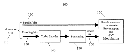
Referring to FIG. 1, there is shown a block diagram of a turbo coding system
100 in
accordance with one embodiment of the invention. The i:urbo coding system is
suitable
for application in ADSL communication systems. The turbo coding system 100
includes
information bits 110 consisting of parallel bits 120 and encoding bits 130,
turbo encoder
means 140, puncturing means 150, coded bits 160, and Gray mapping and QAM
modulation means 170. The encoding system 100 may have stored therein data
representing sequences of instructions which when execui;ed cause the method
described
herein to be performed. Of course, the encoding system 100 may contain
additional
software and hardware a description of which is not nf;cessary for
understanding the
invention.
A portion of the information bits 110, referred to as parallel bits 120, are
mapped 170 to
the signal constellation point directly without any coding. The remaining
portion of the
information bits 110, referred to as encoding bits 130, axe coded by a turbo
encoder 140.
The parallel bits 120 and coded bits 160 are mapped into one QAM signal 170.
In order
to achieve both low computation complexity for the de-mapper and good
performance, a
method in which two independent one-dimensional mappings with concatenated
Gray
mapping is used. This method will be described below.
Two Independent One Dimensional Mappings In typical'. prior art bit-level
turbo coded
QAM schemes, all the transmitted bits are protected by a turbo encoder. These
transmitted bits may be either systematic bits or parity bits. The de-mapper
in typical
prior art schemes has to calculate soft information for all the transmitted
bits. In the
method and system of the present invention, the transmitted bits to be mapped
to a QAM
symbol are of three categories: parallel bits (i.e. which <~.re not protected
by the turbo
code), systematic bits, and parity bits. In the method and system of the
present invention,
11
CA 02353426 2001-07-23
the receiver de-mapper only needs to calculate the soft information for the
systematic and
parity bits. For example, in the case of turbo TCM, for 21x4=16384 QAM, with
the present
invention only 4 soft bits need be calculated rather than 14E soft bits.
The de-mapper calculates the soft information bits from the received
constellation signal
for the turbo decoder by calculating
~'J('Sm ~ f"k )
SmES+
'~k,.i = log (1)
~p(Sn ~~"k)
SnEs
where ~.k,~ is the jth soft bit in the kth QAM symbol, S-"~ is the
constellation signal set
corresponding to the jth bit set to "1", S- is the constellation signal set
corresponding to
the jth bit set to "0", and rk is the received complex sample for the kth QAM
symbol.
Now, let M represent the number of information bit. For a 2'1~ QAM
constellation, the
size of S+ or S- is 2M-1 (i.e. assuming a two dimensional set-partitioning
mapping)
and thus can be very large for a large M. As a result, the soft bit
calculation in equation
(1) becomes computationally intense. However, if one-dirnensional mapping is
used, the
size of S+ or S- becomes 2''~ ~ 2-1. 'This results in a complexity saving
factor of 2 'l~ ~ 2 ,
as shown in Table 1 below. For large constellations, this complexity saving
can be very
significant. Note that the number of addition and multiplication operations
for the soft bit
calculation is proportional to the size of S+ or S-, which is approximately as
large as a
multiple of 16384 for a 16384 QAM signal.
M 2D mapping 1D mapping Saving factor
8 128 8 16
10 512 16 32
12 2048 32 64
14 8192 64 128
12
CA 02353426 2001-07-23
Table 1: Complexity Comparison of 1 D and 2D Mapping
Cohcatehated Gray Mapping. In order to achieve good performance, the present
invention employs a mapping scheme which will be refi~rred to as "concatenated
Gray
mapping". In concatenated Gray mapping, two Gray mappings (i.e. inner and
outer Gray
mappings) are concatenated serially. The inner mapping is for the turbo coded
bits that
include both systematic bits and parity bits, and the outer mapping is for the
uncoded
parallel bits. Referring to FIG. 2, there are shown line dia,~ams 200 of three
examples of
this mapping technique, namely, for 4-ASK 210 (Gra.y mapping), 8-ASK 220 (set
partition mapping plus Gray mapping), and 16-ASK 230 (concatenated Gray
mapping).
In these examples, the two least significant bits are coded 1'~its and are
used for inner Gray
mapping, and the remaining bits are used for outer Gray Mapping. Since the two
least
significant bits are either systematic bits or parity bits, t:he Gray mapping
can provide
equal protection for them. Furthermore, the minimum Euclidean distance for the
uncoded
parallel bits is also maximized by the outer Gray mapping. Therefore, this
technique
ensures good error protection for the encoded bits and the uncoded parallel
bits. A
detailed example of this mapping technique is provided below.
Turbo Coded QAM System with Coding Rate R=2ml(2m+2). Refernng to FIG. 3, there
is shown a block diagram of a turbo coding system 300 with coding rate
2ml(2m+2),
where m>0, in accordance with another embodiment of the invention. Here, the
turbo
coded QAM system with coding rate R=2ml(2m+2) is used to transmit an even
number
of information bits in one QAM symbol. In this embodinnent, 2m information
bits 310,
311, 3I2, 313, 314 are transmitted in each 2 2m+2 QA;M signal 320. Two
identical
recursive systematic convolutional ("RSC") encoders 330, 340 with coding rate
%2 are
employed. Parallel-to-serial 305 and interleaver 370 means are employed. T'he
outputs of
the two encoders 330, 340 are four parity bits 331, 341 for two information
bits 313, 314
and are punctured alternatively (i.e, with different puncturing phase) 350,
360. For every
two information bits (ul , u2 ) 313, 314, two parity bits are left after
puncturing. One parity
bit pul 351 is the parity bit for ul 314, and the other parity bit put' 361 is
the parity bit
13
CA 02353426 2001-07-23
for the interleaved 370 version u2 313. Now, in order t:o have equal
protection for all
information bits, it would be desirable that each information bit have one
parity bit. This
requires that the interleaver 370 permutates the bits at even number positions
to even
number positions and that it permutates the bits at odd mamber positions to
odd number
positions. The two vectors (vo , vl ,..., vm ) 380 and (wo , wl ,..., wm ) 390
will be mapped
320 into two 2m+1-ASK signals independently. For low d;~ta rates, if the
uncoded bits are
absent, (vo , vl ) 380 or (wo , wl ) 390 may be mapped iinto one 4QAM signal
or two
BPSK signals.
In addition, this embodiment employs "concatenated Gray mapping". The vector
(vo , vl ,..., vm ) 380 consists of coded bits (vo, vl ) _ (pu2', u1 ) and
uncoded bits
(v2 , v3 ,..., vm ) . As discussed above in reference to FIG. 2, the coded
bits (vo , v~ ) may
form an inner Gray mapping and the uncoded bits (vz , v3 ,..., v"~ ) may form
an outer Gray
mapping. These two mappings are then concatenated.
Tables 2 through 7 below illustrate the relationship.between QAM size,
parallel bits and
encoded bits, and puncturing pattern and puncturing rate. fn these tables, the
subscript of
the symbol "d" represents the index of QAM symbols in the time domain. The
turbo
coded QAM system of this embodiment may be used for are least the following:
1. Coding rate 2/4 16QAM with bandwidth efficiency of 2bits/Hz;
2. Coding rate 4/6 64QAM with bandwidth efficiency of 4bits/Hz;
3. Coding rate 6/8 256QAM with bandwidth efficiency of 6bits/Hz;
4. Coding rate 8/10 1024QAM with bandwidth efficiency of 8bits/Hz;
5. Coding rate 10/12 4096QAM with bandwidth efficiency of lObits/Hz;
6. Coding rate 12/14 16384QAM with bandwidth efficiency of l2bits/Hz; and,
7. Coding rate 1/2 4QAM with bandwidth efficiency of lbits/Hz.
14
CA 02353426 2001-07-23
Information data dk d~ d2
Encoder input data d~ d2
Parity bit from encoderpl' -
1
Parity bit from encoder- p2'
2
4ASK symbol (I) (dr'.,, pl
)
4ASK symbol (Q) (d2 , p2 )
16QAM (dl '~ PI
', dz , pa')
Table 2: Puncturing and Mapping for 16QAM with Rate 2/4 (transmitting 2 bits)
Information data dk d~ d3 , d4
Encoder input data dl dz
Parity bit from encoderp~' -
1
Parity bit from encoder- p2'
2
BASK symbol (I) (d3', d,~
, pl')
8ASK symbol (Q) (d4', d,-~
, p2')
64QAM (d3', dl',
pl', d4 ,
d2', p2')
* d31, d41 do not go through the convolutional encoder in order to reduce
the decoder complexity.
Table 3: Puncturing and Mapping for 64QAM with Rate 4/6 (transmitting 4 bits)
Information data dk dl , d2 ,~d3
,-d4 , ds
, d6
Encoder input data dT d2
Parity bit from encoderpl' -
1
Parity bit from encoder- p2'
2
16ASK symbol (I) (ds , d3 ,
dr , pl )
,~ _
_.~..~
CA 02353426 2001-07-23
16ASK symbol (Q) (d6~, d4 , d2 , pa )
256QAM (ds-~ ~ yl p ~ d6 , d4
, d2 , pa )
* d31, d4', ds~, d61 do not go through the cortvolutional encoder in order to
reduce the decoder complexity.
Table 4: Puncturing and Mapping for 256QAM witch Rate 6/8 (transmitting 6
bits)
Information data ~d2 ,~d3 ,-d4
dk , ds , d6 ,
d~ , d8
Encoder input data dT d2
Parity bit from encoderpl' -
1
Parity bit from encoder_ pa'
2
32ASK symbol (I) (d~', ds', d3
, dl', pr')
32ASK symbol (Q) (d8', d6', d4
, d2', pz')
1024QAM (d~', ds', d3',
d~', pl ~ ds'~
d6', da', da',pz')
* d31, d41, ..., dal, d81 do hot go through the convolutional encoder in order
to reduce the decoder complexity.
Table 5: Puncturing and Mapping for 1024QAM with Rate 8/10 (transmitting 8
bits)
Information data dk d~ , dl , d3
, d4 , ds ,
d6 , d~ , d8
, d9 , dlo
Encoder input data d? d2
Parity bit from encoderp1' -
1
Parity bit from encoder- p2
2
16
CA 02353426 2001-07-23
f
i
64ASK symbol (I) (d9 , d~ , ds , d3 , dl , pr )
64ASK symbol (Q) (d,ro , ds , d6 , da , d2 , p2 )
4096QAM (d9', d~', ds', d:~ ~ dl'~ pl'~ dlo'~
ds'~ d6'~ da'. dz'~ pa')
* d31, dal, ..., d91, dlol do not go through the' convolutional encoder in
order to reduce the decoder complexity.
Table 6: Puncturing and Mapping for 4096QAM with Rate 10/12 (transmitting 10
bits)
Information data dl , d~ d4 , ds ,
dk d6 , d~ , ds , d9
, dlo dll , dlz
Encoder input data dl d2
Parity bit from pl' -
encoder 1
Parity bit from - p2'
encoder 2
128ASK symbol (I) (drlh d91, d~ , ds
, d3 , dl , pi )
128ASK symbol (Q) (dl2 , dlo , ds ,
d6 , da , dz , p2
)
16384QAM (dl~', d9', d~', ds',
d3 , dl'npl'~ drag
dro'. ds'~ d6'. da'.
da',pa')
* d31, dal, ..., dll', d121 do not go through the convolutional encoder in
order to reduce the decoder complexity.
Table 7: Puncturing and Mapping for 16384QAM with Rate 12/14 (transmitting
12 bits)
Turbo Encoder with Coding Rate R=(2m+1)l(2m+2) for MQAM (M?16). Referring to
FIG. 4, there is shown a block diagram of a turbo coding system 400 with
coding rate
(2m+1)l(2m+2), where m>0, in accordance with another embodiment of the
invention.
Here, the turbo coded QAM system with coding rate R=(2m+1)l(2m+2) is used to
17
CA 02353426 2001-07-23
transmit an odd number of information bits in one QAM symbol. In this
embodiment,
2m+1 information bits 410, 411, 412, 413, 414 are transmitted in each 22m+z
QAM signal
420. For every three information bits 412, 413, 414 pas;>ed into the two RSC
encoders
430, 440, six parity bits 431, 441 are generated. Parallel-to-serial 405 and
interleaver 470
means are again employed. The parity bits generated by each RSC encoder are
punctured
450, 460 with the puncturing rate 5/6 (i.e. 5 of 6 parit~,~ bits are
punctured). The two
puncturing phases (or patterns) 450, 460 are offset three bits from each
other. The
unpunctured bits from the two encoders are multiplexed 495 to obtain the
remaining
parity bits. For each group of three information bits (ul , u,, , u3 ) 412,
413, 414, one parity
bit vo 496 is generated. The parallel bits and coded bits are mapped 420 into
a one-
dimensional ASK signal using concatenated Gray mapping as described above and
as
illustrated in FIG. 2.
Tables 8 through 13 below illustrate the relationship between QAM size,
parallel bits and
encoded bits, and puncturing pattern and puncturing rate. In these tables, the
subscript of
the symbol "d" represents the index of QAM symbols in the time domain. The
turbo
coded QAM system of this embodiment may be used for at least the following:
1. Coding rate 3/4 16QAM with bandwidth efficiency of 3bits/Hz;
2. Coding rate 5/6 64QAM with bandwidth efficiency of Sbits/Hz;
3. Coding rate 7/8 256QAM with bandwidth efficiency of 7bits/Hz;
4. Coding rate 9/10 1024QAM with bandwidth efficiency of 9bits/Hz;
5. Coding rate 11/12 4096QAM with bandwidth efficiency of 1 lbits/Hz; and,
6. Coding rate 13/14 16384QAM with bandwidth efficiency of l3bits/Hz.
Information data dk ~,
d2
,
d3
,
dl
,
d2
,
d3
Encoder input data dl d2 d3 dl d2 d3
Parity bit from encoder- p2 - - -
1
Parity bit from encoder- _ _ _ pZl -
2
4ASK symbol (I) (d3', (d31,
dl') dll)
4ASK symbol (Q) (d2', (dZl'
pa') pll)
18
CA 02353426 2001-07-23
16QAM ~ (ds', dl', da'~ P2') ~ ~d3z~ dr ~ dz ~ P2 )
Table 8: Puncturing and Mapping for 16QAM with Rate 3/4 (transmitting 3 bits)
Information data ~~ dl
dk , dT
d4
, ds
, dl
, dl
, d3
, d4
, ds
Encoder input data dl d2 d3 dl d2 d3
Parity bit from encoder- p2' - - _ _
1
Parity bit from encoder- _ _ _ p2z -
2
8ASK symbol (I) (ds', (ds'.
d3', dsh
dr'.) drl)
8ASK symbol (Q) (d4', (da'~
da', dzl,
PZ',) Pal)
64QAM (ds', (ds'~
d3', d3',
dl', drh
d4', dal,
di dah
~ Pa') Pal)
I
S * d41, dsl, d42, ds2 do not go through the convolutional encoder in order to
reduce the decoder complexity.
Table 9: Puncturing and Mapping for 64QAM with. Rate 5/6 (transmitting 5 bits)
Information data dl ,adz
dk ,- d3 ,
d4 , ds
, d6 ,
d~ , dl
, d2 ,
d3', d4
, ds ,
d6 , d~
*
Encoder input data d~ d2 d3 dl d2 d3
Parity bit from - p2' - _ _
encoder 1
Parity bit from - - _ _ p2 _
encoder 2
16ASK symbol (I) (d~ , ds (d~
, d3 , ,
dl ) ds
,
d3
,
dl
)
16ASK symbol (Q) (d6', d4', (d6
d2', pa') ,
d4
,
d2
,
pz
)
256QAM (d~', ds', (d~
d31 dl ~
~ d6 ~ ds
da , de ,
,p d3
~
dl
~
d6
.
da
,
d
p
)
* d3', ..., d~', d32, ..., d~2 do not go through the convolutional encoder in
order to reduce the decoder complexity.
Table 10: Puncturing and Mapping for 256QAM wiith Rate 7/8 (transmitting 7
bits)
19
CA 02353426 2001-07-23
Information data dl ,~dzr,
dk dTd4 ,~dsT,-d6
d;- , d8
, d9 , dl
, d2 , d3',
d4 , ds
d6 , d~
, d8 ,
d2*
9
Encoder input data dl' d2' d3 a'IZ d2 d3
Parity bit from - pl _ _ _ _
encoder 1
Parity bit from - - - _ -p2 _
encoder 2
32ASK symbol (I) (d9', d~', (d9Z,
ds', d3', d~~
dl') ds
,
d3
,
dl
)
32ASK symbol (Q) (d8', d6', (a8
da'. d2', '
pa') d6
,
d4
,
d2
~
pa
)
1024QAM (d9', d~', (d9Z,
ds', d3', d~
d~', ,
d81 ~ d6'~ ds
d4u dzl ,
~ pa') d3
,
dl
,
d82~
d6
,
d42.
da2,
pat)
* d3', ..., d9', d32, ..., d92 do not go through the convolutional encoder in
order to reduce the decoder complexity.
Table 11: Puncturing and Mapping for 1024QAM with Rate 9/10 (transmitting 9
bits)
Information data dl~, d2
dk , d3 ,
d4 , ds
, d6 ,
d~ , d8
, d9 ,
dlo , dll
, dl ,
d2 , d3
d4 , ds
,
d6Z~ d~2
ds2, d92,
dloZ. dlrz
Encoder input data dl' d2' d3 dl~ d2 d3
Parity bit from encoder- p2 _ _ _ _
1
Parity bit from encoder- - - _ p2 _
2
64ASK symbol (I) (dll', d9', (dm
d~', ds', .
dj', dl dv
) .
d~
~
ds
,
d3
,
dl
)
64ASK symbol (Q) (dlo , d8 (dro
, d6 , ,
d4 , da da
~ pa~ ~
d6
~
d4
.
da
~
pz
)
4096QAM (dm'~ dv', (dllz.
d~', ds', d92~
d3', d'r d~z.
~ ds
dloh d8', ~
d6', d4', d3
da', pa') ~
dl
dloz,
ds2:
d62,
d42,
d22,
p2z)
CA 02353426 2001-07-23
* d31... dlll, d3z... d112 do hot go through th:e convolutional encoder in
order to reduce the decoder complexity.
Table 12: Puncturing and Mapping for 4096QAM with Rate 11/12 (transmitting
11 bits)
Information data dl , d2
dk , d3 ,
d4 , d
6 h ,
d8 , d9
, dlo
, dll
, d12
~ dl3
, dl d2
.
d32~ d42.
ds2 d62~
d;2, dgZ,
d92, d142.
4112 d122,
d132 ~
Encoder input data dl d2 d3 dl d2 d3
Parity bit from encoder- p2 - - _ _
1
Parity bit from encoder- - - - p2 -
2
128ASK symbol (I) (dl3 . (dl3
dll . ~ dll
d9 , d~ ~ d9
, ds ~ ~ d7
d3' ~ ~ ds
dl ) ~ d3
~ dl
)
128ASK symbol (Q) (dla', (dl2l~
dlo'. dloz~
dg'~ d6'~ d8z~
da'~ dl' d6Z~
~ j~2') d4z.
d2~~
p2
)
16384QAM (dl3 , (d13
dm , d9 ~ dll
, d~ , ~ d9
ds . d3' ~ d7
~ d~ ~ ds
I 1 1 1 ~ d3
I I 1 ~ dl
dlz ~ dlo ,
~ ds , 2 2
ds ~ d4 2 2
, da .~ 2 2
pz ) 2
dra
~ dlo
~ d$
, d6
~ d4
~ dz
~ p2
)
* d31... d131, d32... d132 do not go through the convolutional encoder in
order to reduce the decoder complexity.
Table 13: Puncturing and Mapping for 16384QAM with Rate 13/14 (transmitting
13 bits)
Universal Implementation of Turbo Coded QAM for MQAM. Referring to FIG. 5,
there
is shown a block diagram of a universal turbo coding system 500 using mode
control
with coding rates 2ml(2m+2) and (2m+1 )l(2m+2), where m>0, in accordance with
another
embodiment of the invention. Here, a universal implementation system
applicable to the
embodiments illustrated in FIG. 3 and FIG. 4 for coding rates R=2ml(2m+2) and
R=(2m+1 )l(2m+2) is described. The puncture rate for each RSC encoder 530, 540
is
21
CA 02353426 2001-07-23
either P=1/2 for coding rate R=2ml(2m+2) or P=5/6 for coding rate
R=(2m+1)l(2m+2).
This puncture rate is controlled by a mode control signal 565 having states
corresponding
to even and odd numbers of information bits 510, 511, 512, 513, 514. The
parity bits
from the two conventional encoders are evenly and alternatively punctured 550.
The
parallel-to-serial transfer means ("P/S") 505 is also controlled by the mode
565, which
will control whether u3 512 is used or not by the P/S transfer 505 and the
encoders 530,
540. Interleaver 570 means are again employed. The constellation mapper 520 is
also
controlled by the mode 565, which will indicate the posiltion of the least
significant bit.
Finally, the bits passed into the RSC encoders 530, 540 and their parity bits
are grouped
into two 2-bit vectors (vo , vl ) and (wo , wl ) 580, 5'90. Then, (vo , vl
,..., vm ) and
(wo, wl,..., wm ) 580, 590 are mapped 520 into an ASK signal format, if a
large
constellation MQAM (i.e. M516) is used, or they are mapped 520 into one 4QAM
signal
or two BPSK signals, if 4QAM or BPSK is employed.
Geheral Coded QAM Using Ahy Turbo Codes The embodiments discussed above in
reference to the turbo coded QAM systems of FIG. 3, FIfG. 4, and FIG. 5 used
double
parallel concatenated convolutional encoders, with each encoder employing a
coding rate
1 /2 convolutional encoder. However, the invention may make use of different
kinds of
turbo codes (e.g. a parallel concatenated convolutional encoder with each
encoder using a
coding rate other than 1/2, a multiple parallel concatenated convolutional
encoder (refer
to D. Divsalar, and F. Pollara, "Multiple Turbo Codes for Deep-Space
Communications",
JPL TDA Progress Report 42-121, May 15, 1995), serial concatenated turbo codes
(refer
to S. Benedetto, D. Divsalar, G. Montorsi, and F. Pollaxa, "Serial
Concatenation of
Interleaved Codes: Performance Analysis, Design, and Iterative Decoding", JPL
TDA
Progress Report 42-126, August 15, 1996), etc.). Referring to FIG. 6, there is
shown a
block diagram of a general turbo coding system 600 using any turbo coding
method with
coding rate 2ml(2m+2), where m>0, in accordance with another embodiment of the
invention. In this embodiment, any kind of turbo code ma',~ be used for an
overall coding
rate of 2ml(2m+2). For every QAM symbol 620, two parity bits are used, the
number of
input bits 613, 614 to the turbo encoder 630 is two, and the number of parity
bits after
22
CA 02353426 2001-07-23
puncturing 650 is two. This embodiment has an output/input ratio 666 of 2/2.
Referring
to FIG. 7, there is shown a block diagram of a general tort>o coding system
700 using any
turbo coding method with coding rate (2m+1)l(2m+2), where m>0, in accordance
with
another embodiment of the invention. In this embodiment, any kind of turbo
code may be
used for an overall coding rate of (2m+1)l(2m+2). For every QAM symbol 720,
one
parity bit is used, the number of input bits 712, 713, 714 to the turbo
encoder 730 is three,
and the number of parity bits after puncturing 750 is one. This embodiment has
an
output/input ratio 766 of 1/3. Referring to FIG. 8, there :is shown a block
diagram of a
universal turbo coding system 800 using mode control anel any turbo coding
method with
coding rates 2ml(2m+2) and (2m+1)l(2m+2), where m»D, in accordance with
another
embodiment. In this embodiment, any turbo code m;ay be used for coding rates
2ml(2m+2) and (2m+1)l(2m+2). This embodiment employs mode control 865.
Coded QAM Using Turbo Product Codes and Low ~~ensity Parity Check (LDPC)
Codes Other powerful coding schemes such as turbo product codes (refer to D.
Chase,
"A Class of Algorithms for Decoding Block Codes", IEEE Trans. Inform. Theory,
Vol.
IT-18, pp. 170-182, Jan. 1972; and, R. Pyndiah, "Near Optimum Decoding of
Product
Codes: Block Turbo Codes", IEEE Trans. Common., Vol. COM-46, No. 8, pp. 1003-
1010, August 1998) and low-density parity check (LDPC) codes (refer to R. G.
Gallager,
"Low-Density Parity Check Codes", IRE Trans. Inform. Theory, vol. IT-8, pp. 21-
28,
Jan. 1962; D. J. C. Mackay and R. M. Neal, "Near Shanfaon Limit Performance of
Low
Density Parity Check Codes", Electon. Lett., vol. 32, No. 18, pp.1645-1646,
Aug. 1996;
and, D.J.C. Mackay, "Good Error-Correcting Codes Based on fiery Sparse
Matrices",
IEEE Tran. Inform. Theory, vol. 45, No. 2, pp. 399-431, nrlar. 1999) may also
be used in
the coded QAM system of the present invention. Referring to FIG. 9, there is
shown a
block diagram of a turbo product or low-density parity check ("LDPC") coding
system
900 with coding rate 2ml(2m+2), where m>0, in accordan<;e with another
embodiment of
the invention. In this embodiment, a turbo product code or LDPC code 930 for
the coding
rate (2m+1 )l(2m+2) is employed. Referring to FIG. 10, there is shown a block
diagram of
a turbo product or low-density parity check ("LDPC") coding system 1000 with
coding
23
-.., .y.: ~.___ ....~~,.~. -__ __- ~~_.
CA 02353426 2001-07-23
rate (2m+1)l(2m+2), where m>0, in accordance with another embodiment of the
invention. In this embodiment, a turbo product code or LDPC code 1030 for the
coding
rate (2m+1)l(2m+2) is employed. Referring to FIG. 11, there is shown a block
diagram of
a universal turbo product or low-density parity check ("LDPC") coding system
1100
S using mode control with coding rates 2ml(2m+2) and (:Zm+1)l(2m+2), where
m>0, in
accordance with another embodiment of the invention. In this embodiment, a
turbo
product code or LDPC code 1130, with mode control 1165, for the coding rates
2ml(2m+2) and (2m+1 )l(2m+2) are employed.
Extension Case: More Coded Bits for Turbo Codes wit~~ Coding Rate R=2ml(2m+2).
Although the number of coded bits to be mapped to Q is preferably two as
described in
the preceding embodiments, this number is not limitef, to two and may be
greater.
However, in practice, coding more than six bits may be counter productive as
the
puncturing required may lead to diminished performance of the turbo code.
Referring to
FIG. 12, there is shown a block diagram of a turbo coding; system 1200 with
coding rate
2ml(2m+2), where m>0, where the four least significant bits are encoded by
turbo codes,
and where the puncturing rate is 3/, in accordance with another embodiment of
the
invention. In this embodiment, three coded bits are used in PAM mapping. Four
information bits 1212, 1213, 1214, 1215 are inputted to two turbo encoders
1230, 1240
generating eight parity bits. At the output 1231, 1241 of the two encoders
1230, 1240, the
parity bits are punctured 1250, 1260 with puncturing rate 3/ (i.e. three
parity bits are
punctured out of four bits). The puncturing phases for thc; two encoders 1230,
1240 are
offset by two bits. For every four information bits (ur , u2, u3, u4 ) 1212,
1213, 1214,
1215, two parity bits (wo ; vo ) 1251, 1261 remain after puncturing 1250,
1260. The two
vectors (vo , vi ,..., vm ) and (wo , wl ,..., wm ) 1280, 1290 arcs mapped
1220 into two 2 m+i -
ASK signals independently using "concatenated Gray mapping". The coded bits
(vo , vl , v2 ) (or (wo , wl , w2 ) ) consisting of systematic bits (vl , v2 )
(or (wi , w2 ) ) and one
parity bit vo (or wo ) use Gray mapping and the uncoded bits (v3 , v4 ,..., vm
) (or
(w3, w4,..., wm ) ) use Gray mapping. Tables 14 through 18 below illustrate
the
24
CA 02353426 2001-07-23
relationship between QAM size, parallel bits and encoded bits, and puncturing
pattern
and puncturing rate. In these tables, the subscript of the symbol "d"
represents the index
of QAM symbols in the time domain. In addition, other codes such as LDPC codes
and
product turbo codes may be used in the manner of the embodiment described
above in
association with FIG. 9 but where the input bits are (~~l , u2 , u3 , u4 ) .
The turbo coded
QAM system of this embodiment may be used for at least the following:
l . Coding rate 4/6 64QAM with bandwidth efficiency of 4bits/Hz;
2. Coding rate 6/8 256QAM with bandwidth efficien<;y of 6bits/Hz;
3. Coding rate 8/10 1024QAM with bandwidth efficiE,ncy of 8bits/Hz;
4. Coding rate 10/12 4096QAM with bandwidth efficiency of lObits/Hz; and,
5. Coding rate 12/14 16384QAM with bandwidth efficiency of l2bits/Hz.
As mentioned above, this system may be extended to encode six information bits
by
using a puncturing rate of 5/6 with an offset of three bits.
Information data dk d 2
,
d3
,
d4
Encoder input data dl d~ d3 d4
~
Parity bit from encoderpl' - - -
1
Parity bit from encoder_ _ p3' -
2
8ASK symbol (I) (d3',
dl
,
pl')
8ASK symbol (Q) (d4
,
d2
,
p3
)
64QAM (d3'~
dl',~II
,
G~4',
d2',
p3')
Table 14: Puncturing and Mapping for 64QAM with Rate 4/6 (transmitting 4 bits)
Information data dk dTTd3',
d4
,
ds
,
d6
Encoder input data dl d2 d3 d4
Parity bit from encoderpl' - - _
1
CA 02353426 2001-07-23
Parity bit from encoder- - p3 -
2
16ASK symbol (I) (dsr,
dd3
, dl
, pl
)
16ASK symbol (Q) (d6',
d4 ,
d2',
p3')
256QAM (ds',
d3',
d j',
pr ,
a'6',
da',
a'z'
~ ps')
*dsl, d61 do not go through the convolutional encoder in order to reduce
the decoder complexity.
Table 15: Puncturing and Mapping for 256QAM with Rate 6/8 (transmitting 6
bits)
Information data dk d~ ,
d~
da
, ds
, d6
, d~
, d8
*
Encoder input data dl d2 d3 d4
Parity bit from encoderpl' - - -
1
Parity bit from encoder- - p3 -
2
32ASK symbol (I) (d~
, ds
, d3
, d~
, pl
)
32ASK symbol (Q) (d8
, cd6
, da
, d2
, p3
)
1024QAM (d~
~ ds
~ ds
~ dl
~pl
~ da
~ d6
~ da
~ da
~p3
)
*dsl, d61, dal, d81 do not go through the convolutional encoder in order to
seduce the decoder complexity.
Table 16: Puncturing and Mapping for 1024QAM with Rate 8/10 (transmitting 8
bits)
26
CA 02353426 2001-07-23
Information data dk dl',
d2',
d3',
d4
, ds',
...,
d9',
dlo'
Encoder input data dl d2 d3 d4
Parity bit from encoderpl - - -
1
Parity bit from encoder- - p3' -
2
64ASK symbol (I) (d9',
d~',
ds
, d3',
dl',
pl')
64ASK symbol (Q) (dlo',
d8
, d6',
d4',
d2',
p3')
4096QAM (d9',
d~',
ds',
d3',
dr',
pl',
d101.
d81,~
d61~
d41~
d21,j731)
*dsl, d61, ..., d91, dlol do not go through the convolutional encoder in
order to reduce the decoder complexity.
Table 17: Puncturing and Mapping for 4096QAM with Rate 10/12 (transmitting
bits)
Information data dk dl ,
d2
, d3
, d4
, ds
, ...,
dll
, dlz
*
Encoder input data dl d2' d3 d4
Parity bit from encoderpl' - - -
1
Parity bit from encoder- - p3 -
2
64ASK symbol (I) (dll',
d9',
d~
, ds',
d3',
dl',
pl')
64ASK symbol (Q) (d12'.
dlo',
ds
, d6',
da',
d2',
p3')
4096QAM (dll',
d9',
d~
, ds',
d3',
dl',
pl',
d121~
d101~
<~81~
d61~
d41~
d21~j~3')
*dsl, d61, ..., dlll, d121 do not go through the' convolutional encoder in
order to reduce the decoder complexity.
27
CA 02353426 2001-07-23
Table 18: Puncturing and Mapping for 16384QA1~!t with Rate 12/14 (transmitting
12 bits)
Extension Case: Mope Coded Bits of Turbo Codes with Coding Rate
R=(2m+1)l(2m+2). Referring to FIG. 13, there is shown a block diagram of a
turbo
coding system 1300 with coding rate (2m+1)l(2m+2), where m>0, where the six
least
significant bits are encoded by turbo codes, and where the puncturing rate is
9/10 in
accordance with another embodiment of the invention. In this embodiment, three
coded
bits are again used in PAM mapping. Five information bits 1312, 1313, 1314,
1315, 1316
are inputted to two turbo encoders 1330, 1340 generatin;; ten parity bits. At
the output
1331, 1341 of the two encoders 1330, 1340, the parity bits are punctured 1350,
1360 with
puncturing rate 1/10 (i.e. nine parity bits are punctured out of ten bits).
The puncturing
phases for the two encoders 1330, 1340 are offset by five bits. For every five
information
bits (u i , u2 , u3 , u4 , a 5 ) 1313, 1313, 1314, 1315, 1316, one parity bit
vo 1396 is left after
puncturing 1350, 1360. The two vectors (vo , vl ,..., vm ) and (wa , wl ,...,
wm ) 1380, 1390
will be mapped 1320 into two 2m+i _ASK signals independently using
"concatenated
Gray mapping". The coded bits (vo , vl , v2 ) consisting of systematic bits
(vl , v2 ) and one
parity bit vo use Gray mapping, the coded bits (systematic bits only) (wo, wl,
w2 ) use
Gray mapping, and the uncoded bits (v3 , v4 ,..., vm ) (or (w3, w4 ,...; wm )
) use Gray
mapping. Tables 19 through 23 below illustrate the relationship between QAM
size,
parallel bits and encoded bits, and puncturing pattern and puncturing rate. In
these tables,
the subscript of the symbol "d" represents the index of QA:M symbols in the
time domain.
In addition, other codes such as LDPC codes and product turbo codes may be
used in the
manner of the embodiment described above in association with FIG. 10 but where
the
input bits are (ul , u2 , u3 , u4 , us ) . The turbo coded QAM system of this
embodiment may
be used for at least the following:
1. Coding rate 5/6 64QAM with bandwidth efficiency of Sbits/Hz;
2. Coding rate 7/8 256QAM with bandwidth efficiency of 7bits/Hz;
28
~.. __ .~._____ ,.~T__ _..
CA 02353426 2001-07-23
3. Coding rate 9/10 1024QAM with bandwidth efficiency of 9bits/Hz;
4. Coding rate 11/12 4096QAM with bandwidth efficiency of l lbits/Hz; and,
5. Coding rate 13/14 16384QAM with bandwidth efficiency of l3bits/Hz.
Again, this system may be extended to coding seven information bits by using a
puncturing rate of 13/14 with an offset of 7 bits.
Furthermore, and in the manner of the embodiment described above in
association with
FIG. 8, a universal implementation may be obtained for the embodiments
described in
association with FIG. 12 and FIG. 13 for turbo codes. Moreover, and in the
manner of the
embodiment described above in association with FIG. 11, a universal
implementation
may be obtained for the embodiments described in association with FIG. 12 and
FIG. 13
for LDPC and product codes.
Information data dl dl
dk , ,
d2 d2
, ,
d3 d3
, ,
d4 d4
, ,
d~ ds
~
Encoder input data dl dZ d3 d4 d~ dl dl d3 d4 ds
Parity bit from p3
encoder 1
Parity bit from p3'
encoder 2
8ASK symbol (I) (ds', (ds',
d3', d3',
dl') dl')
8ASK symbol (Q) (d4', (d4',
d2', d2',
p3') p3')
64QAM (ds', (ds',
d3', d3',
dl', dl',
1 2
I 2
I 2
da~d2~p3) d4~da~p3)
Table 19: Puncturing and Mapping for 64QAM with Rate 5/6 (transmitting 5 bits)
Information data dl dl
dk , ,
d~, d2
d4 ,
,ids d3
,-...,d~ ,
d4
,
ds
,
...,
d~
Encoder input data dl d2 ~ d4 dT dl dl d3 d4 ds
d3
Parity bit from p3'
encoder 1
29
- .. ~ ..~.~....~_-_____7..
CA 02353426 2001-07-23
Parity bit from ~ ~ p3
encoder 2
8ASK symbol (I) (d~ (d~
, ,
ds ds
, ,
d3 d3
, ,
d~ dl
) )
8ASK symbol (Q) (ds', (d6z.
d4', d4~,
d2', d2
P3') ,
p3
)
64QAM (d~', (d~
ds', ,
d3', ds
dl', ~
d6,' d3
d41 ~
~ dl
d2l d62~
p31 d42~
) d22~
p32)
*d61, d~', d62, d~2 do hot go through the convolutional encoder in order to
reduce the decoder complexity.
Table 20: Puncturing and Mapping for 256QAM with Rate 7/8 (transmitting 7
bits)
Information data dl dl
dk ,Tdzr, ,
dT d2
,~, ,
...,~~ d3
~ ,
d4
,
ds
,
...,
d9
Encoder input data ~ d2 d3 d4 ds dl d2 d3 d4 ds
Parity bit from p3
encoder 1
Parity bit from p3
encoder 2
32ASK symbol (I) (d9', (d9
d~ '
, d7
ds', ,
d3', ds
dl') ,
d3
,
dl
)
32ASK symbol (Q) (ds'~ (dsz,
d6'~ d6z,
d4'~ daZ,
da'~ da
p3') ~
ps
)
1024QAM (d9', (d9z,
d~', d~Z,
ds', ds
d3', ,
dl', d3
d81. ,
d61. dl
da', ,
d2l d82.
p31) d62,
da2,
d22,
p32)
*d61, d~', d8', d9', d6 , d~2, d82, d92 do not go through the cohvolutional
encoder in order to reduce the decoder complexity.
Table 21: Puncturing and Mapping for 1024QAM with Rate 9/10 (transmitting 9
bits)
.~...~_ . ,_.. ~..
CA 02353426 2001-07-23
Information data dl dl
dk , ,
d2 d2
, ,
d3 d3
, ,
d~..., d4
I~ ,
ds
,
...,
dll
Encoder input data dl d2 d3 d4 ds dl d2 d3 d4 ds
Parity bit from p3
encoder 1
Parity bit from p3
encoder 2
32ASK symbol (I) (dlll, ~a112'
d91, d9
dal, d7
dsh ,
d31' d,5
dll~ ,
d3
,
dl
)
32ASK symbol (Q) (dlo'; (d10'.
d8', d8'.
d6', d6'~
d4', d4',
d2', d2',
p3') p3')
1024QAM (dll (dll
. ~
d9 dv
~ ~
do, d~
ds ~
, ds
d3 ,
, ds
dl ,
, dl
d101~ ,
d81~ d102.
dbh d82~
d41, d62~
d21, d42,
p31) d22,
p32)
*d61, dal, ..., dlll, d6 , d~2, ..., dll2 do not go through the convolutionczl
encoder in order to reduce the decoder complexity.
Table 22: Puncturing and Mapping for 4096QAM with Rate 11/12 (transmitting
11 bits)
Information data dl dl
dk , ,
d2 d2
, ,
d3 d3
,~d4 ,
,-dsl, d4
..., ,
dr3 ds
,
...
Encoder input data dl d2 d3 d4 ds dl d2 ~ d~ ds
d3
Parity bit from p3
encoder 1
Parity bit from p3
encoder 2
64ASK symbol (I) (dl3'~ (dl3'~
dll'~ dll~~
d9'~ dv'~
d7'~ d~'.
ds', dsh
d3', d3h
dl dl')
)
64ASK symbol (Q) (d12 (d12
, ~
dlo d10
~ .
ds d8
~ ~
d6 d6
~ ~
d4 d~
, ,
dz p3
, )
p3
)
16384QAM (d13', (d13~~
dll'. dll'.
d9', dv'~
di d~',
, ds',
ds', dsh
d3', dh,
dl 2
, 2
I 2
1 2
1 2
I 2
I 2
1 dl2
1 ~
dl2 d10
~ .
d10 d8
~ ~
d8 d6
~ ~
d6 d4
. ,
d4 d2
, ,
d2 p3
, )
p3~
)
*d61, dal, ..., 4131, d62, d~2, ..., d132 do not go t,~Crough the
convolutional
encoder in order to reduce the decoder com,~lexity.
31
CA 02353426 2001-07-23
Table 23: Puncturing and Mapping for 16384QAM: with Rate 13/14 (transmitting
13 bits)
Referring to FIG. 8, the method of one embodiment ~of the invention will now
be
described. With this method turbo codes may be effectively used in ADSL
communication systems. At a step 1, M information bits 810, 811, 812, 813, 814
to be
transmitted over an ADSL communication system are divided into two categories:
encoding bits 812, 813, 814 and parallel bits 810, 811.
At a step 2, after parallel-to-serial transfer 805, the encoding bits 812,
813, 814 are
passed into a turbo encoder 830. The parallel bits 810, 811. bypass the turbo
encoder 830.
The encoder outputs, after puncturing 850, are coded bits which consist of
systematic bits
and parity bits (i.e. either all parity bits or partial parity bi.ts).
Alternate turbo codes such
as serial concatenated turbo codes or multiple turbo codes :may be used.
Rather than using
a turbo encoder, turbo product codes or LDPC codes may be used.
At a step 3, the coded bits and parallel bits are mapped E~20 into two PAM
signals. For
small PAM, there are no parallel bits. The coded bits are used as least
significant bits, and
the parallel bits are used as the most significant bits. The number of coded
bits to be
mapped to PAM is preferably two for transmitting an even number of bits and
preferably
three for transmitting an odd number of bits. The mapping of coded bits and
parallel bits
to PAM signals is performed using concatenated Gray mapping where concatenated
Gray
mapping is a serial concatenation of an inner Gray mapping and an outer Gray
mapping.
The inner Gray mapping is used for the coded bits. The outer Gray mapping is
used for
the parallel bits. To transmit an even number of bits, say M 2m bits,
preferably 2m-2 bits
of the total 2m bits are parallel bits that will bypass the turbo encoder. The
remaining
preferably 2 bits will pass through the turbo encoder. Two parity bits are
generated after
puncturing. In this case, the overall bandwidth efficiency is 2m bits/Hz using
QAM. To
transmit an odd number of bits, say M--2m+1 bits, preferably 2m-2 bits of the
total 2m+1
bits are parallel bits that will bypass the turbo encoder. The remaining
preferably 3 bits
will pass through the turbo encoder. One parity bit is generated after
puncturing. In this
32
CA 02353426 2001-07-23
r
case, the overall bandwidth efficiency is 2m+1 bits/Hz using QAM. Mode control
865
may be employed in which a first mode may be used for transmitting an even
number of
bits and a second mode may be used for transmitting an odd number of bits.
Although the
number of coded bits to be mapped to PAM is preferably two, this number may be
greater than two.
At step 4, a QAM signal is generated 820 from the two PAM signals, one for the
real part
and the other for the imaginary part. The QAM signal is tlhen transmitted over
the ADLS
communication system.
G.lite and G.dmtADSL. Now, there have been a number of proposals to apply
powerful
turbo coding and decoding techniques to G.lite and G.dmt ADSL to improve
transmission.
rate and loop reach (refer to C. Berrou and A. Glavieux, "Neat Optimum Error
Correcting Coding and Decoding: Turbo-Codes", IEEE T'rans. Commun., vol. COM-
44,
No. 10, October 1996, pp. 1261-1271). Among them, thE;re are two typical turbo
TCM
schemes. The first is a symbol-level turbo TCM scheme which was proposed by
Robertson and Worz (refer to P. Robertson and T. Worz, "Bandwidth-E~cient
Turbo
Trellis-Coded Modulation Using Punctured Component Codes", IEEE J-SAC, vol.
16,
No. 2, Feb. 1998, pp. 206-218; and, "Performance Simulation Results on Turbo
Coding", ITU Standard Contribution, NT-112, Nashville, USA, November 1999).
The
other is a bit-level turbo TCM scheme (refer to "Proposed Evaluation of
Proposed TTCM
(PCCC) with R-S Code and without R-S Code", ITU Standard Contribution, D.748
(WPl/15), Geneva, Switzerland, April 2000; "Proposal and Performance
Evaluation of
TTCM (PCCC) with R-S Code", ITU Standard Contribution, FI-122, Fiji Island,
Feb.
2000; and, "New Proposal of Turbo Codes for AZ)SL Modem", ITU Standard
Contribution, BA-020, Antwerp, Belguim, June 2000). With respect to the bit-
level
scheme, several designs have been proposed (refer to S. Benedetto, D.
Divsalar, G.
Montorsi, and F. Pollara, "Parallel Concatenated Treli'is Coded Modulation",
IEEE
ICC96, 1996, pp. 974-978).
Referring to FIG. 14, there is shown a block diagram of a bit level turbo TCM
system
1400 in accordance with the prior art. Information bits 14:10 are encoded by
two parallel
33
CA 02353426 2001-07-23
concatenated recursive systematic convolutional encoders (RSCs) 1420, 1430
with an
interleaves 1440 between their inputs. The two encoders ,are identical and
have a coding
rate of R=1/2. The respective sets of parity bits output from the encoders are
punctured
1450 in a predetermined pattern in order to reduce the parity overhead. Then,
the
systematical information bits and parity bits are grouped :1460 and
subsequently mapped
into a QAM constellation 1470. Although this prior art scheme has good error
performance, it also has some drawbacks including the following: all
information bits are
passed into the convolutional encoders for protection, therefore the number of
trellis
transitions is very large and the decoder is very complicated; the puncturing
and mapping
patterns are different for different constellation sizes of QAM, which leads
to high
implementation complexity; and, high coding rates cannot be obtained for large
constellation sizes because over puncturing will damage the code, and
therefore high data
rates cannot be achieved.
According to another embodiment of the invention, a universal turbo TCM system
is
provided which has both good error performance and low decoder complexity. In
general,
this TCM system comprises: a pair of recursive systematic; convolutional (RSC)
encoders
for generating parity bits from input bits; an interleaves for interleaving
input bits to the
encoders; a puncture unit for determining a puncture rate of the parity bits
in response to
an even and odd number of information bits; and, a bit grouping module for
receiving the
punctured bits and the input bits and grouping the bits for snapping into a
symbol.
Referring to FIG. 15, there is shown a block diagram of a turbo TCM encoder
system
1500 with a coding rate of R=1/2 for 4QAM or a group of two 2QAM in accordance
with
another embodiment of the invention. This turbo TCM encoder may be used to
transmit 1
bit in one 4 QAM symbol or in two 2 QAM symbols. For each information bit
1510, two
parity bits are generated by two recursive systematic convolutional (RSC)
encoders 1520,
1530. The parity bits generated by each RSC encoder are; punctured 1540
alternatively,
that is, one half of the total parity bits are punctured. The overall coding
rate is R=1/2.
For each information bit v2 1550, one parity bit vl 1560 is generated. (vl,
v2) are
34
CA 02353426 2001-07-23
mapped 1570 into one 4QAM symbol using Gray mapping. The system includes an
interleaves 1580 between the two encoders 1520, 1530.
Referring to FIG. 16, there is shown a block diagram of a turbo TCM encoder
system
1600 with a coding rate of R=(2+2m)/(4+2m) for MQAM, where 111516 and M--2m,
in
accordance with another embodiment of the invention. Tlhis turbo TCM encoder
system
may be used to transmit an even number of information bits in one QAM symbol.
For
every two information bits (v3, v4) 1610, 1620 passed into the RSC encoders
1630, 1640,
four parity bits are generated by these encoders. The par.'~ty bits generated
by each RSC
encoder are punctured alternatively, that is, one half of the total parity
bits are punctured
1650, 1660. For every two information bits (v3, v4) 1610, 1620, two parity
bits (vl, v2)
1670, 1680 are generated. (vl, v2, ... v2m) are mapped 1690 into one QAM
symbol
using set-partition mapping (refer to G. Ungerboe;ck, "Channel Coding with
MultilevellPhase Signals", IEEE trans., Inform. Theory, vol. IT-28, No. 1,
January 1982,
pp. 55-67) and Gray mapping. It is preferable that this mapping be operated in
one
dimension, that is two halves of (vl, v2, ... v2m) are mapped into two 2m-ASK
signals.
This system may be used for at least the following: coding rate 2/4 16QAM;
coding rate
4/6 64QAM; coding rate 6/8 256QAM; coding rate 8/10 1024QAM; coding rate 10/12
4096QAM; and, coding rate 12/14 16384QAM.
Referring to FIG. 17, there is shown a block diagram of a turbo TCM encoder
system
1700 with a coding rate of R=(3+2m)/(4+2m) for MQAM, where lt?516 and M--2m,
in
accordance with another embodiment of the invention. This turbo TCM encoder
system
may is used to transmit an odd number of information bits in one QAM symbol.
For
every 3 information bits passed into the two RSC encoders 1730, 1740, 6 parity
bits are
generated by the two encoders. The parity bits generated by each RSC encoder
are
punctured 1750, 1760 with a puncturing rate of 5/6, tlhat is, 5 of 6 parity
bits are
punctured. For every three information bits (v2 , v3, v4), one parity bit vl
is generated.
(vl, v2,..., v2m) are mapped 1790 into one QAM symbol using set-partition
mapping and
Gray mapping. It is preferrable that this mapping be operated in one
dimension, that is,
two halves of (vl, v2,..., v2m) are mapped into two 2m -ASK signals. This
system may be
CA 02353426 2001-07-23
used for at least the following: coding rate 3/4 16QAM; coding rate 5/6 64QAM;
coding
rate 7/8 256QAM; coding rate 9/10 1024QAM; coding rate 11/12 4096QAM; and,
coding rate 13/14 16384QAM.
Referring to FIG. 18, there is shown a block diagram of a universal turbo TCM
encoder
system 1800 for MQAM in accordance with another embodiment of the invention.
Here,
the data paths of embodiments 1600 and 1700 are combined via the interleaver
1810
which interleaves the bits at even numbered positions to even numbered
positions and the
bits at odd numbered positions to odd numbered positions. The puncture rate
1840 for
each RSC encoder 1820, 1830 is either 1/2 or 5/6 which ins selected based on
the even or
odd status of the number of information bits. The information bits are passed
into the
RSC encoders 1820, 1830 and their parity bits are grouped 1850 into 4-bit by 4-
bit for
MQAM (M>4) or they are grouped 1850 into 2-bit by 2-bit for 4QAM. In general,
this
embodiment of the invention includes the following: a pair of recursive
systematic
convolutional (RSC) encoders 1820, 1830 for generating parity bits from input
bits; an
interleaver 1810 for interleaving input bits to the encodlers; a puncture unit
1840 for
determining a puncture rate for the parity bits in response to the even or odd
status of the
number of information bits; and, a bit grouping module 1850 for receiving the
punctured
bits and the input bits and grouping the bits for mapping into a symbol. The
interleaver
1810 may include a pair of interleavers. This pair of interl~eavers may be
implemented by
an interlearver with even and odd patterns. The mapping; 1860 may comprise
mapping
one two-dimensional QAM into two one-dimensional ASK. The mapping 1860 may
include a mixed Gray mapping and set partition mapping; And, the mapping 1860
may
include concatenated Gray mapping.
For embodiments of the invention including 1600, 1700, and 1800, and with
reference to
the discussion of concatenated Gray mapping and FIG. 2 above, note that two
unique
mapping schemes may be employed to achieve better error performance. The first
mapping scheme may be a mixed Gray mapping with set partition mapping. With
this
mapping scheme, the mapping of (vl, v2, ... v2m) into 2~2m QAM is operated by
mapping each half of (vl, v2, ... v2m) into one 2m -ASK signal. For example,
(vl, v3, ...
36
CA 02353426 2001-07-23
v2m-1) may be mapped into one 2m -ASK signal and (v:Z, v4, ... v2m) may be
mapped
into another 2m -ASK signal. Again, FIG. 2 illustrates this unique mapping
(i.e. set
partition plus Gray mapping) for 4-ASK 210 and 8-ASIA 220. For 4-ASK 210, Gray
mapping is employed. For 8-ASK 220, the first most significant bit employs set
partition
mapping and the two least significant bits employ Gray mapping. For general 2m
-ASK,
the first (m-2) most significant bits employ set partition mapping and the two
least
significant bits employ Gray mapping. For example, suppose that Bl, B2, ...,
B2m are a
mapping for 2m -ASK (m>1), where Bk (1<k<_2m) is an m-bit string, then the
mapping
for 2m+1 -ASK may be generated as 1B1, 1B2, ..., lB2m, OBl, OB2, ..., OB2m,
that is, a
1 bit is appended to all Bl, B2, ..., B2m to obtain the first half and a 0 bit
is appended to
all B1, B2, ..., B2m to obtain the second half. The second unique mapping
scheme may
be concatenated Gray mapping. With this second schemE;, both the coded bits,
such as
(vl, v3) or (v2, v4), and the uncoded bits, such as (v5, v7, ".., v2m-1) or
(v6, v8, ..., v2m),
both employ Gray mapping and these mappings are conca~.tenated. For example,
for m =
4, both (vl, v3) and (v5, v7) are Gray mappings. The concatenated Gray code is
illustrated in line diagram 230 of FIG. 2. The two leas significant bits are
the Gray
mapping of coded bits (vl, v3), which will repeat every four mappings. The two
most
significant bits are the Gray mapping of the uncoded bits (v5, v7), which are
the same for
each group of 4 mappings.
Function Block fog Small Constellation Sizes Referrin~; to FIG. 19, there is
shown a
block diagram of a turbo TCM system 1900 in accordance with the prior art
(refer to
D.V. Bruyssel, "G.gen: Performance Simulation Res~!lts on Turbo Coding", ITU
Telecommunication Standardization Sector NT-112, Nashville, Tennesse, Nov. 1-
5,
1999). In this scheme, parallel bit streams pass through two parallel
convolutional
encoders 1910, 1920. The scheme includes an interlea~~er 1930 located between
the
encoders. Two sets of coded bits are mapped 1940, 1950 into a constellation
point
independently. These points are then alternately 1960 pas;>ed to the channel,
that is, one
constellation point is punctured out for a given DMT symbol. One drawback with
this
scheme is that it can only support a minimum constellation of size of eight,
that is, it
37
CA 02353426 2001-07-23
a
cannot map to bins or subchannels with smaller constellation sizes of, say,
two or four.
This may become problematic as loop reach increases and SNR are lowered.
Referring to FIG. 20, there is shown a block diagram oiF a turbo TCM encoder
system
2000 in accordance with another embodiment of the invention. This system
includes a
mufti-dimensional constellation construction function block 2010 which enables
smaller
constellations to be grouped together to accommodate a minimum of 3 coded
bits. The
function block (i.e. tone ordering bin grouping) 2010 is introduced to order
the tones
based on constellation sizes and to group them accordingly to form mufti-
dimensional
constellations. The function block 2010 interfaces with the signal mappers
2020, 2030 to
control bits-to-point mapping. The bin grouping may be flexible enough to
handle
different bin loading scenarios. Table 24 lists exemplary mufti-dimensional
constellation
construction scenarios for small constellations.
Case Grouping Scenario Constellation
Dimension
1 Four b=1 bins 4
2 Two b=1 bins and One b=2 4
bin
3 Two b=2 bins 4
*b is the humbe~ of bits that a bin (i.e. subcizannel) caries.
Table 24: Bin Group Summary
This embodiment of the invention may be used with many different mapping
alternatives.
In general, for a given encoder, the mapping scheme should give roughly the
same error
protection for each constellation dimension. For example, consider Case 3 from
Table 24
above. Here, one of three coded bits from the encoders, say the bottom one,
may be used
to select one of the two bins and the remaining two bits may be used to select
4QAM
points in each bin. The added function block 2010 allows. for the construction
of multi-
dimensional constellations with small constellation sizes of two and four.
This allows
turbo codes to be applied in low SNR environments.
38
CA 02353426 2001-07-23
Y . ~ n
Although the invention has been described with reference to certain specific
embodiments, various modifications thereof will be app~~rent to those skilled
in the art
without departing from the spirit and scope of the invention as outlined in
the claims
appended hereto.
39