Language selection

Search

Patent 2353717 Summary

Third-party information liability

Some of the information on this Web page has been provided by external sources. The Government of Canada is not responsible for the accuracy, reliability or currency of the information supplied by external sources. Users wishing to rely upon this information should consult directly with the source of the information. Content provided by external sources is not subject to official languages, privacy and accessibility requirements.

Claims and Abstract availability

Any discrepancies in the text and image of the Claims and Abstract are due to differing posting times. Text of the Claims and Abstract are posted:

  • At the time the application is open to public inspection;
  • At the time of issue of the patent (grant).
(12) Patent Application: (11) CA 2353717
(54) English Title: SCREW JACK
(54) French Title: VERIN A VIS
Status: Dead
Bibliographic Data
(51) International Patent Classification (IPC):
  • B66F 3/08 (2006.01)
  • B66F 3/10 (2006.01)
  • B66F 13/00 (2006.01)
(72) Inventors :
  • KAWASAKI, YASUJI (Japan)
(73) Owners :
  • KAWASAKI INDUSTRIAL CO., LTD. (Japan)
(71) Applicants :
  • KAWASAKI INDUSTRIAL CO., LTD. (Japan)
(74) Agent: FETHERSTONHAUGH & CO.
(74) Associate agent:
(45) Issued:
(22) Filed Date: 2001-07-24
(41) Open to Public Inspection: 2003-01-24
Examination requested: 2001-07-24
Availability of licence: N/A
(25) Language of filing: English

Patent Cooperation Treaty (PCT): No

(30) Application Priority Data: None

Abstracts

English Abstract


The present invention relates to a screw jack that has a thin metal
bearing for supporting a main screw shaft of a jack body to lift the jack body
high as possible so that a torque increase can be kept to a minimum. For
this purpose, the metal bearing is mounted and configured to have a
substantially large outer diameter, and also a small stepped sliding-surface
is formed on the top or bottom surface of the metal bearing.


Claims

Note: Claims are shown in the official language in which they were submitted.


WHAT IS CLAIMED IS:

1. A screw jack comprising:
a jack body;
a main screw shaft that stands on the jack body;
a thin metal bearing arranged on a bottom surface of a jack body;
and
a stepped sliding-surface formed on the top or bottom surface,
wherein
the thin metal bearing receives and supports the main screw shaft
on the jack body and is constructed so as to have a large outer diameter,
while the stepped sliding-surface is constructed so as to have a small
diameter.

-6-

Description

Note: Descriptions are shown in the official language in which they were submitted.


CA 02353717 2001-07-24
SPECIFICATION
TITLE OF THE INVENTION : SCREW JACK
BACKGROUND OF THE INVENTION
FIELD OF THE INVENTION
This invention relates to a screw jack used for raising a structural
object or a work piece, and more particularly to a screw jack that utilizes a
screw.
DESCRIPTION OF THE PRIOR ART
The conventional automatic three-stage screw jack, as shown in Fig.
6, is structurally designed to equip a ball bearing C on a bed B at a lower
end of an external cylinder A to receive and support a screw shaft D on the
ball bearing C. Therefore, there is a disadvantage that the jack is able to
raise an object only up to a level from which the thickness of the ball
bearing has subtracted.

CA 02353717 2001-07-24
SLTMMARY OF THE INVENTION
An object of the present invention is to provide a screw jack that is
able raise an object up to a higher level in comparison with the conventional
one.
According to the present invention, there is provided a screw jack
that comprises a thin metal bearing arranged on a bottom surface of a jack
body, where the thin metal bearing receives and supports a main screw
shaft on the jack body. The thin metal bearing is constructed so as to have
a large outer diameter while a stepped sliding-surface is constructed so as to
have a small diameter and provided on the top or bottom surface of the
large-diameter metal bearing. . _

CA 02353717 2001-07-24
BRIEF DESCRIPTION OF THE DRAWINGS
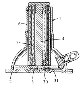
Fig. 1 is a vertical cross sectional front view of the screw jack in
accordance with the present invention;
Fig. 2 is a front view that illustrates a condition in which the screw
jack is being elevated high;
Fig. 3 is a set of a plan view Fig. 3-a, a vertical cross sectional view
Fig. 3-b and a bottom view Fig. 3-c for illustrating an exemplified metal
bearing to be installed on the screw jack of the present invention;
Fig. 4 is a set of a plan view and a vertical cross sectional front view
for illustrating another exemplified metal bearing to be installed on the
screw jack of the present invention;
Fig. 5 is a set of a plan view and a vertical cross sectional front view
for illustrating still another exemplified metal bearing to be installed on
the
screw jack of the present invention; and
Fig. 6 is a front view of the conventional screw jack.
-3-

CA 02353717 2001-07-24
DETAILED DESCRIPTION OF THE PREFERRED EMBODIMENTS
A screw jack as one of preferred embodiments of the present
invention will be described with reference to Figs. 1 to 5.
Reference numeral 1 denotes a jack body where a metal bearing 3 is
installed on a bed 2 arranged on a lower end of the jack body and a main
screw shaft 4 stands on the bed 2 by being received and supported by the
metal bearing 3. The metal bearing 3 is structurally designed to have a
substantially large outer diameter in comparison with the conventional one.
In addition, a stepped sliding surface 31 is formed on the top or bottom
surface of the metal bearing 31. The stepped sliding surface 31 is
structurally designed to have a small turning-radius~to relatively facilitate
its sliding action for keeping a torque increase to a minimum. In the
present invention, the outer diameter of the metal bearing is enlarged in the
design in advance so that it may be easy to be materialized and it may be
excellently stabilized. Thus, only the size of the sliding surface 31 is
lessened to keep a torque increase to a minimum by facilitating its sliding
action. Furthermore, reference numeral 6 denotes a case and 7 denotes an
external cylinder.
According to the present invention, as described above, the thickness
of the metal bearing is substantially smaller than that of the conventional
ball bearing, so that the jack body is of a high level type, compared with the
conventional one, resulting in excellent features of the jack. In addition,
the metal bearing is structurally designed to have a large diameter in
comparison with that of the conventional one, so that it ensures stability.
Furthermore, a stepped sliding surface is formed on the top or bottom
surface of the metal bearing and structurally designed to have a small
-4-

CA 02353717 2001-07-24
turning-radius, so that its sliding action is facilitated and a torque
increase
can be kept to a minimum.
-5-
Representative Drawing
A single figure which represents the drawing illustrating the invention.
Administrative Status

For a clearer understanding of the status of the application/patent presented on this page, the site Disclaimer , as well as the definitions for Patent , Administrative Status , Maintenance Fee  and Payment History  should be consulted.

Administrative Status

Title Date
Forecasted Issue Date Unavailable
(22) Filed 2001-07-24
Examination Requested 2001-07-24
(41) Open to Public Inspection 2003-01-24
Dead Application 2004-11-05

Abandonment History

Abandonment Date Reason Reinstatement Date
2003-11-05 R30(2) - Failure to Respond
2004-07-26 FAILURE TO PAY APPLICATION MAINTENANCE FEE

Payment History

Fee Type Anniversary Year Due Date Amount Paid Paid Date
Request for Examination $400.00 2001-07-24
Registration of a document - section 124 $100.00 2001-07-24
Application Fee $300.00 2001-07-24
Maintenance Fee - Application - New Act 2 2003-07-24 $100.00 2003-07-09
Owners on Record

Note: Records showing the ownership history in alphabetical order.

Current Owners on Record
KAWASAKI INDUSTRIAL CO., LTD.
Past Owners on Record
KAWASAKI, YASUJI
Past Owners that do not appear in the "Owners on Record" listing will appear in other documentation within the application.
Documents

To view selected files, please enter reCAPTCHA code :


To view images, click a link in the Document Description column. To download the documents, select one or more checkboxes in the first column and then click the "Download Selected in PDF format (Zip Archive)" or the "Download Selected as Single PDF" button.

List of published and non-published patent-specific documents on the CPD .

If you have any difficulty accessing content, you can call the Client Service Centre at 1-866-997-1936 or send them an e-mail at CIPO Client Service Centre.


Document
Description 
Date
(yyyy-mm-dd) 
Number of pages   Size of Image (KB) 
Representative Drawing 2002-03-07 1 18
Cover Page 2002-12-30 1 41
Abstract 2001-07-24 1 15
Description 2001-07-24 5 119
Claims 2001-07-24 1 15
Drawings 2001-07-24 4 79
Assignment 2001-07-24 4 130
Prosecution-Amendment 2003-05-05 2 79
Fees 2003-07-09 1 38