Note: Descriptions are shown in the official language in which they were submitted.
CA 02353728 2001-05-31
WO 00/32946 PCT/CA99/01129--
WEDGE ANCHOR FOR CONCRETE
BACKGROUND OF THE INVENTION
1. Field of the Invention
The present invention relates to fasteners and, more
particularly, to expandable fasteners for mounting to concrete structures,
and the like.
2. Description of the Prior Art
Expandable anchors of many different types are already
known. More particularly, expandable anchors have been developed for
insertion into a hole formed in a support structure such that a cylindrical
expansion sleeve of the anchor may be selectively expanded into
frictional contact with the inside peripheral surface of the hole such that
the anchor becomes frictionally anchored in the support structure.
Typically, the expandable anchor includes an elongated expander member
having a threaded first end and a flared second end opposite the first end
with a cylindrical surface extending between the first and second ends
around which there is provided the aforementioned expansion sleeve.
The threaded first end is like a headless screw and extends outwardly of
the support structure once the expandable anchor is positioned in the hole
thereof. A nut threaded on the visible part of the threaded first end may
be used as an actuating mechanism with an object to be secured to the
support structure being typically located between the nut and the support
structure as the threaded first end of the expandable anchor extends
through this object. By rotating the nut, it engages the outer surface of the
object and thus bears upon it such as to pull the expander member in an
outward direction. As the expansion sleeve is already sufficiently
frictionally engaged with the inside surface of the hole, when the
expandable anchor is pulled by the rotation of the nut, the expansion
sleeve stays substantially stationary in the hole and thus, as the expander
member is pulled out of the hole, the flared second end of the expander
member causes the cylindrical expansion sleeve to expand radially
outwardly thereby increasing a friction between the expansion sleeve and
the hole and thus further securing the expandable anchor therein.
Since the expansion sleeve must already be frictionally
engaged with the hole before the expandable anchor is pulled, the outside
diameter of the expansion sleeve must be similar to, even slightly greater
1
CA 02353728 2001-05-31
WO 00/32946 PCT/CA99/01129
than, the inside diameter of the hole in order to ensure an initial frictional
contact therebetween which will then allow the expansion sleeve to
remain still in the hole while the expander member is pulled outwardly
thereof and thus allow the expansion sleeve to be expanded by the flared
end of the expander member. This diameter of the expander member, at
rest, results in that the expandable anchor when initially inserted in the
hole must be inconveniently driven with significant force therein as the
expansion sleeve is already frictionally engaged with the inside wall of
the hole. The flared end then acts as a wedge to expand the expansion
sleeve into greater frictional contact with the inside of the hole.
For instance, United States Patent No. 2,647,431 issued on
August 4, 1953 to Lewis discloses an expansion bolt comprising a hollow
shell having a leading end adapted to be expanded by a wedge into
frictional contact with the peripheral wall of a hole. Resilient spurs, in
some cases as part of a separate bail, are provided at opposite trailing ends
of the shell, i.e. the end which is nearest to the opening of the hole, in
order to engage the wall of the hole and prevent initial rotation of the
shell relative to the hole until the shell frictionally engages the wall.
United States Patents No. 3,250,170 issued on May 10,
1966 to Siegel, No. 3,620,120 issued on November 16, 1971 to Warner,
No. 4,337,012 issued on June 29, 1982 to Sohnius, No. 4,403,894 issued
on September 13, 1983 to Clark, No. 5,028,188 issued to July 2, 1991 to
Prince and No. 5,344,257 issued on September 6, 1994 to Wright et al. all
disclose to expand a shell in a direction normal to a hole axis such that the
periphery of the shell frictionally engages a wall of the hole. Notably,
United States Patent Nos. 3,620,120, 5,028,188 and 5,344,257 each
describes having a resilient shell for facilitating the introduction of the
expandable anchor within a hole while providing sufficient holding
pressure to prevent the shell and associated wedge member from spinning
in the hole as a torque is applied to a bolt for axially displacing the wedge
member such as to radially expand the shell.
United States Patents No. 2,783,673 issued on March 5,
1957 to Lewis et al. and No. 5,352,066 issued on October 4, 1994 to
Schaeffer et al. also both disclose an expandable shell for facilitating the
installation thereof within a hole. The leading end of the shell may be
expanded at an angle with respect to the central axis of the hole.
2
CA 02353728 2001-05-31
WO 00/32946 PCT/CA99/01129
Also known are undercut wedge anchors, wherein the hole
formed in the support structure is enlarged with a tool at a distance from
the visible opening of the hole such that the expandable undercut wedge
anchor may thereafter be inserted in the hole until its expansion sleeve
becomes located behind a shoulder defined at the junction of the enlarged
area and the remainder of the hole. Once expanded, the expansion sleeve
may abut this shoulder and thus retain the anchor in position in the
support structure.
SUMMARY OF THE INVENTION
It is therefore an aim of the present invention to provide an
improved expandable wedge anchor for use in holes in various materials,
e.g. concrete.
It is also an aim of the present invention to provide an
expandable wedge anchor having an expander member and an expansion
member capable of spring-like deformation.
It is a further aim of the present invention to provide an
expandable wedge anchor wherein the expansion member is capable of
being expanded at a trailing end thereof.
It is a still further aim of the present invention to provide an
expandable wedge anchor wherein the expansion member may be rotated
in the hole such that its trailing end produces an undercut in the hole into
which the expanded trailing end nests.
It is a still further aim of the present invention to provide a
spiral wedge anchor also in accordance with the present invention.
Therefore, in accordance with the present invention, there is
provided an expansion wedge anchor for insertion in a hole delimited by a
wall, comprising an expander means and an expansion means, said
expansion means being provided at a leading end of said expander means,
said expander means comprising flaring means, said expansion means
being expandable at a trailing end thereof and being adapted to engage the
wall of the hole when said expander means is positioned in the hole,
wherein upon longitudinal withdrawal of said expander means from the
hole, said expander means displaces longitudinally relative to said
expansion means with said flaring means thereof gradually causing said
3
CA 02353728 2010-06-29
trailing end of said expansion means to expand. whereby a trailing edge of
said expansion means engages the wall of the lr.ole.
More particularly, said trailing end is adapted, when
expanded by said flaring means, to extend at an angle with respect to a
longitudinal axis of said expander means.
Also in accordance with the present invention, there is
provided a method of setting an expansion wedg:: anchor in a hole
delimited by a wall. comprising the steps of': (a) providing an expander
member and an expansion member; and (b) displacing said expander
member such as to cause a trailing end of said expansion member to
engage the wall ot't.lie hole.
More particularly, in step (b), said trailing end is expanded
such as to extend at all angle with respect to a longitudinal axis of said
expander member.
Further in accordance with i.lh-e present: invvention, there is
provided an expansion wedge anchor for insertion in ;a hole delimited by a
%vall, comprising an expander means and all expansion means, said
cxpan;,iml means being provided at, a leading end of said expander n)eans,
said expander means cornprisin g a leading flaring means and a trailing
flaring means both disposed on the leading end of s::aid expander means,
said expander means comprising a threaded section on a trailing end
thereof, said expansion means including leading and trailing ends and
being expandable at said trailing end and being adapted to engage the wall
of the hole when said expander means is positioned in the hole, the
expansion means defining a leading support adapted to contact a bottom
of the hole and adapted to stop movement of the expansion means within
the Dole, when the expander means is positioned in the laole, while said
expander means is adapted to relatively continue to move towards the
bottom of the hole to engage said trailing flaring me;tns of said expander
means with a trailing edge of said expansion means tc expand said trailing
end of said expansion means within the hole, wherein, upon longitudinal
withdrawal of said expander means from the hole, said expander means
displaces longitudinally relative to said expansion means with said leading
flaring means gradually causing at least one of said leading and trailing
ends of said expansion means to expand, whereby a leading, edge of said
expansion meals engages the wall of the hole.
4
CA 02353728 2010-06-29
Still lurthcr in accordance with the pre:salt invention, there
is provided a method of setting an expansion wedge anchor in a hole
delimited by a wall, the method comprising the steps =:)f:
(a) providing an expander Member and in expansion
member,
(b) displacing said expander member such as to cause the
trailing end of said expansion member to engage the wall of the hole,
wherein said trailing end is expanded such its to extend at an angle with
respect to a longitudinal axis of'said expander member; and
(c) displacing said expander member relative to said
expansion member such as to cause it leading en.l of said expansion
member to enrage the wall ot't.he bole.
Still further in accordance with the present invention, there
is provided an expansion wedge anchor for insertion in a hole delimited
by a wall, Comprising an expander means and an e>:pansion ameans, said
expansion means being provided it a leadin end of;taid expander means,
said expander means comprising flaring
means, said expansion means
11tcll}(lI leading and trailing cruls and being expandable at said trailing
end and being adapted to cng.ige the will] of the hole When said expander
means is positioned in the hole. wherein upon longit_idinal withdrawal of
said expander means from the hole, said expander means displaces
longitudinally relative to said expansion means with said flaring means
thereof gradually causing at least one of said leading and trailing ends of
said expansion means to expand, whereby at least o.:ie of a leading edge
and a trailing edge of said expansion means engages the wall of the hole,
wherein said flaring means comprise a flared end which tapers towards
said threaded section, an intermediate seetion tieing provided proximally
of said flared end and having it diameter less than that of said threaded
section, said inwrinediate section providing space to accommodate
outwardly thereof at least part of said expansion means in a collapsed
position thereof at least. for during insertion of said anchor in the hole.
Still further in accordance with the present invention, there
is provided an expansion wedge anchor for insertion in a hole delimited
by a wall, comprising an expander means and an expansion means, said
expansion means being provided at a leading end of said expander means,
said expander means comprising a leadin flaring means and a trailing
flaring means ] oth disposed on the leading end of said expander means.
.1 a
CA 02353728 2010-06-29
said expansion means including leading and trailing ends and being
expandable at said trailing end and being adapted to engage the wall of't.he
hole when said expander means is positioned in the hole, wherein, when
said expander mains is positioned in the hole, said expander means is
adapted to move relative to said expansion means and towards the bottom
of the hole such that said trailing flaring means of said expander means
en ld tr,
_Ragcs satrailing end of'saaid expansion means thereby expanding said
trailing end of said expansion means within the hole.
Still further is accordance with the present invention, there
is provided all expansion wedge anchor for insertion in a hole delimited
by a wall, comprising an expander means and an expansion means, said
expansion means being provided at a leading end of: aid expander means.
said expansion means being expandable at a trailing end thereof and being
adapted to engage the wall c:Ii' the hole when said expander means is
positioned in the. hole, wherein, with said expander means positioned in
the hole. said expander means is adapted to be withdrawn from the hole
while moving relative to said expansion means such ;hat. said leading end
of said expander MQUTIs engages said expansion means and causes said
trailing end of'saaid expansion means to expand and fi -nly engage the wall
of the hole.
BRIEF DESCRIPTION OF T1:1E DRAWINGS
Having thus generally described the nature of the invention,
reference will now be made to the accompanying drawings, showing by
wily of illustration a preferred embodiment thereof; and in which:
Figs. I A and Iii are longitudinal cross-=seCl.ional views of a
first variant of a non-slip wedge anchor in accordance with the present.
invention shown respectively in at rest. and installed positions thereof;
Fig. I C is a bottom plan view of the anchor of -'ig,. I A;
Figs. 2A and 213 are longitudinal cross-sectional views of a
second variant of a non-slip wedge anchor in accor&,.rnce with the present
iavcfticait shown respectively in at rest and assembled positions thereof;
Figs. 3A and 313 are respectively ele'iational and bottom
plan views of an expander member of the anchor of Figs. 2A and 2B;
Figs. 3C'. 31.) and 3E are respectively front elevational, side
clevationaal and bottom plan views of an expansion member of the anchor
of Figs. 2A and 21:3;
41.)
CA 02353728 2010-06-29
l i rs. 4A and 413 a are longitudinal cross-sectional views of a
third variant of a non-slip wcclt-,e anchor in accordance with the present
invention shown respectively in at rest and assembled positions thereof;
P'igs. 5A and 513 are respectively clevational and bottom
plan views of an expander member of the anchor of Figs. 4A and 413;
4c
CA 02353728 2001-05-31
WO 00/32946 PCT/CA99/01129
Figs. 5C, 5D and 5E are respectively front elevational, side
elevational and bottom plan views of an expansion member of the anchor
of Figs. 4A and 4B;
Figs. 6A and 6B are longitudinal cross-sectional views of a
fourth variant of a non-slip wedge anchor in accordance with the present
invention shown respectively in at rest and assembled positions thereof;
Figs. 7A and 7B are respectively elevational and bottom
plan views of an expander member of the anchor of Figs. 6A and 6B;
Figs. 7C, 7D and 7E are respectively front elevational, side
elevational and bottom plan views of an expansion member of the anchor
of Figs. 6A and 6B;
Figs. 8A and 8B are longitudinal cross-sectional views of a
first variant of an undercut wedge anchor in accordance with the present
invention shown respectively in first and second positions thereof in a
support structure;
Figs. 9A to 9D are respectively front elevational, side
elevational, bottom plan and top plan views of an expander member of the
undercut wedge anchor of Figs. 8A and 8B;
Figs. 9E to 9G are respectively front elevational, side
elevational and bottom plan views of an expansion member of the
undercut wedge anchor Figs. 8A and 8B;
Figs. IOA to 10D are respectively front elevational, side
elevational, bottom plan and top plan views of a second variant of an
undercut wedge anchor in accordance with the present invention;
Figs. I1A to 11C are respectively front elevational, side
elevational and top plan views of a third variant of an undercut wedge
anchor in accordance with the present invention;
Figs. 12A to 12C are respectively front elevational, side
elevational and bottom plan views of a fourth variant of an undercut
wedge anchor in accordance with present invention;
Figs. 13A to 13C are respectively front elevational, side
elevational and bottom plan views of a fifth variant of an undercut wedge
anchor in accordance with present invention;
Fig. 14A is a front elevational view of a spiral wedge
anchor also in accordance with the present invention;
Fig. 14B is a variant of the spiral wedge anchor of Fig. 14A;
CA 02353728 2001-05-31
WO 00/32946 PCT/CA99/01129
Fig. 14C is a top plan view of either anchor of Figs. 14A
and 14B; and
Fig. 15 is a vertical cross sectional view showing the spiral
anchor wedge of Fig. 14A in an expanded position within a hole defined
in a support structure such that the anchor retains an object to this support
structure.
DESCRIPTION OF THE PREFERRED EMBODIMENTS
A) NON-SLIP WEDGE ANCHORS (FIGS. 1 TO 7)
The purpose of this new non-slip expansion anchor concept
is to provide an improved anchor design capable of achieving superior
performance over convention al type expansion anchors presently offered.
Another area to be considered is that of the effect of vibratory loading on
the anchor performance. This is relevant considering the anchor is
designed to provide minimal relaxation of the anchor assembly after
installation. In conventional expansion anchors the bolt tends to loosen
after the initial setting torque has been applied and as a result it must be
re-tightened to establish the proper clamping load. The positive set
between the anchor bolt and clip segments will provide minimal slip or
creep once the anchor is set and the load is applied to the anchor.
Figs. 1A and 113 illustrate a non-slip wedge anchor 10 in
accordance with the present invention which is shown respectively in at
rest and installed positions thereof. In Fig. 1 C, the anchor 10 is seen from
its underside. The anchor 10 includes an expander member 12 and an
expansion member 14. The expander member 12 is designed to be
inserted in a hole H defined in a support structure S, such as a concrete
element, and comprises a treaded section 16 adapted to extend in the hole
H while having a proximal end 18 which extends outside of the hole H
such as to be engaged by a threaded female member, such as a nut N, with
a washer W being herein shown between the nut N and the support
structure S. Typically, an object, although not herein shown, is held by
the anchor 10 to the support structure S; it is noted that, in the present
embodiment, as well as in the other embodiments of the various anchors
herein shown and described, such an object has not been illustrated.
6
CA 02353728 2001-05-31
WO 00/32946 PCT/CA99/01129
The expander member 12 also includes a flared distal end
20 around which is provided the expansion member 14 which is
dimensioned to frictionally engage the walls of the hole. Once the anchor
has been introduced in the hole H, the nut N is rotated to displace the
expander member 12 translationally outwardly of the hole H, As the
friction forces between the expansion member 14 and the hole H are
sufficient for it to remain stationary therein during the displacement of the
expander member 12, the flared end 20 of the expander member 12
causes the expansion member to expand, as seen in Fig. 1B, thereby
anchoring the anchor 10 in the hole H. The expansion member includes a
double-layered, folded over, proximal or trailing end 22 which defines an
internal abutment shoulder 24 which can be engaged by an enlarged
annular flange 26 provided distally of the flared end 20 of the expander
member 12.
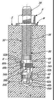
In Figs. 2A and 2B, a second wedge anchor 30 in
accordance with present invention is illustrated and which comprises an
expander member 32 (shown in detail in Figs. 3A and 3B) and an
expansion member 34 (shown in detail in Figs. 3C to 3E), or expandable
clip. The expander member 32 is similar to the expander member of Fig.
IA in that it includes a treaded section 36, :having a proximal end 38, a
leading flared end 40 and a reduced diameter intermediate cylindrical
section 42 therebetween. A shoulder 44 is defined at a junction of the
intermediate and threaded sections 42 and 36.
The expansion member 34 comprises a leading support 46,
an expandable collar 48 and a leg 50 connecting the support 46 and collar
48 together. The collar 48 is split at 52 to allow it to expand, as seen in
Fig. 2B, and defines thereat mating tongue and groove elements 54 and
56, respectively. As seen in Figs. 2A and 2B, the leg 50 of the expansion
member 34 is held captive in a groove 58 defined longitudinally in the
flared end 40 (see Figs. 3A and 3B) thereby preventing the expansion
member 34 from rotating with respect to the expander member 32 and
forcing it to work vertically without twisting.
In operation, the rotation of the nut N causes the expander
member 32 to displace longitudinally and outwardly along the hole H. As
the collar 48 of the expansion member 34 frictionally engages the walls of
the hole H, it remains stationary therein while the groove 58 slides along
7
CA 02353728 2001-05-31
WO 00/32946 PCT/CA99/01129
the leg 50. It is noted that the leg 50 is biased outwardly, i.e. to an open
or
deployed position, to ensure the initial frictional engagement of the collar
48 with the walls of the hole H. It is also noted that the outside surface of
the collar 48 is knurled for additional friction..
The partial withdrawal of the expander member 32 from the
hole H causes the flared end 40 to expand outwardly the collar 48 with a
trailing edge 60 of the collar 48 engaging the walls of the hole H at an
angle with respect to a longitudinal axis of the hole H (see Fig. 2B). Such
an engagement with the hole H at a trailing end of the expandable
member 34, and with an angle opposed to that of the flared end 40, is very
secure and increases the force required to pull out the expanded anchor 30
from the support structure S.
It is noted that the cylindrical intermediate section 42 allows
the collar 48 to be received in a collapsed position (see Fig. 2A) when the
anchor 30 is initially driven in the hole H. Also, the shoulder 44 prevents
the expandable member 34 from moving upon the threaded section 36 of
the expander member 32. The tongue and groove elements 54 and 56
align the collar 48 at its split 52 to provide a peripheral, 360 -like,
gripping of the expandable member 34 into the walls of the hole H.
The expandable member 34 is also provided on its leg 50
with a reinforcement rib 62 to provide more rigidity to the leg 50. The
leading support 46 of the expandable member 34 comprises a concave
bottom 64 to still give more rigidity to the leg 50. At the very end of the
flared section 40 of the expander member 32 is a radial flat section land
66 to allow, for maximum interference between the hole H, the expander
member 32 and the expansion member 34.
In the following descriptions which pertain to variants of
the anchor 30 of Figs. 2A and 2B, components which are identical in
function and in structure to corresponding components of the anchor 30
bear the same references as in Figs. 2A to 3E, whereas similar parts have
been attributed suffixes to their reference numerals with respect to the
numerals used in Figs. 2A to 3E. Any components which are new to the
anchors of the following variants are identified by new reference
numerals.
8
CA 02353728 2001-05-31
WO 00/32946 PCT/CA99/01129
In Figs. 4A to 5E and 6A to 7E, third and fourth wedge
anchors 70 and 80, respectively, also in accordance with present invention
are illustrated. These anchors 70 and 80 are very similar to the anchor 30,
except that their respective expansion members 34a and 34b have
respectively 2 and 3 legs 50a and 50b, respectively, as opposed to the
single leg 50 embodied in the expansion member 34 of anchor 30. The
multiple splits 52b result in that the collar 48b includes three clip
segments.
The expansion member 34b of anchor 80 defines a pair of
rounded radii 82 and 84 to increase the rigidity of the legs 50b.
Therefore, with respect to the anchor of Figs. 6A to 7E', the
new wedge concept is made up of two components. One is a specially
formed stud or expander member which is partially threaded at one end.
Assembled to the bottom end is a multi segment expansion clip or
expansion member which is assembled to the flared end of the stud
opposite the threaded end.
The stud (Figs. 7A and 7B) is made of high strength steel
which can be heat treated for heavy duty applications. The stud is unique
in that it contains a number of features unlike conventional wedge type
anchors. The stud is comprised of an external thread at one end which
has a reduced diameter at the bottom end of the thread which engages the
multi segmented clip. The difference in diameter prevents the clip from
travelling upward onto the threads of the bolt. The end of the bolt
.opposite to the thread end has a flared section extending outward. The
end of the flare incorporates several guide segments used to maintain the
position of the expansion member as it expands during installation and is
also used to prevent rotation of the total clip itself. At the very end of the
flared section of the bolt is a radial flat section land to allow for maximum
interference between the hole, stud and expansion clip.
The expansion clip (Figs. 7C to 7E) is made of high strength
steel and is comprised of three formed segments which are'pre-expanded
prior to assembly. Each of the segments compresses against the hole in
the concrete when driven into the hole providing frictional resistance to
axial pullout during installation and after the load is applied.
Each segment is connected to a formed concave shaped
section via a formed leg section. Each leg connecting a segment has a
9
CA 02353728 2001-05-31
WO 00/32946 PCT/CA99/01129
strengthening rib and internal radii to add rigidity to the clip assembly.
Another feature located on each segment is a locking tab which helps
control expansion and keep the clip segments in line. This provides for a
full 360 degree expansion. A portion of each is knurled to provide
additional friction and holding power.
Anchor Installation/Function
A nut/washer is assembled to the threaded end of the stud
assembly. The embedment is determined and measured from directly
under the washer to the bottom end of the bolt. The anchor is driven into
a pre-drilled hole in the concrete. As the anchor is driven into the hole
using a hammer, the pre-expanded segments of the clip assembly provide
the frictional resistance to resist the axial pullout resulting during the
initial setting of the anchor.
As the installation torque is increased, the nut is tightened
flush against the flat washer and the concrete. As a result the tapered
portion at the bottom of the stud is pulled upward into the clip segments
causing expansion of the lower clip segments located toward the bottom
portion of the bolt (see Fig. 6B). The constant outward force provided by
the upper section of the segments cause the clip segments to dig into or
interfere with the concrete thus preventing the clip assembly from sliding
or creeping upward which causes the bolt to loosen in the hole of the
concrete. Once the installation torque is reached, the load can be applied
to the bolt.
B) UNDERCUT WEDGE ANCHOR (FIGS., 8 TO 13
The purpose of this undercut type anchor concept is to
provide a high strength instant holding mechanical type anchor designed
to achieve superior pullout performance in concrete while provided a
positive lock into the concrete to prevent anchor slip or creep.
The feature of being instant holding makes it suitable for
applications needing to apply the load immediately which is not the case
with chemical type anchors. This anchor must be capable of withstanding
both vibratory and shock type loads without failure. Failure would be
determined by the improved load versus displacement relationship.
CA 02353728 2001-05-31
WO 00/32946 PCT/CA99/0I I29
Figs. 8A and 8B illustrate an undercut wedge anchor 100 in
accordance with the present invention which is shown respectively in first
and second positions thereof in a support.
The undercut anchor 100 consists of two specially formed
components, namely a stud or expander member 102 and a clip or
expansion member 104, both made of high strength steel to provide the
resistance needed to overcome the forces acting as a result of the high
installation torque required to set the anchor into the concrete. Existing
designs consist of more than two assembled components.
The expander member 102 which is made of high strength
steel to resist heavy duty tension and shear applications comprises a
threaded section 106, a proximal hex drive element 108 located at the top
or beginning of the threaded section as a positive means of providing the
spinning or rotational action to the anchor 100 during installation. The
standard hex element 108 allows the use of a conventional type socket
type drive for fast access and easy removal.
At the opposite end of the expander member 102 is a
specially designed stud configuration that provides a means to expand the
undercut mechanism (or expansion member 104) which will provide the
positive lock between the expander member. 102 and the concrete of the
support structure S. This stud configuration consists of longitudinal
opposed first leading and second trailing flared portions 110 and 112,
respectively. The trailing tapered portion. 112, located towards the
threaded section 106, provides a means of expanding the undercut
mechanism or expansion member 104 which in turn defines the undercut
into the concrete. At a proximal end of the trailing flared portion 112, is a
collar 114 which is used to prevent the undercut mechanism or expansion
member 104 from moving onto the threaded section 106 of the expander
member 102.
The leading flared portion 110 provides a means of
expanding the bottom portion, or distal end, of the expansion member
104, to thus complete the undercut/locking process. At the end of each
flared portion is a specially formed configuration to prevent the expansion
member 104 from rotating free of the expander member 102 during the
initial undercut action and during the final installation process.
11
CA 02353728 2001-05-31
WO 00/32946 PCT/CA99/01129--
The multiple function specially designed undercut
mechanism /expansion member 104 which is made of high strength steel
comprises an expandable collar 116, a leading support 118 and a pair of
legs 120, reinforced with ribs 122, connecting the expandable collar 116
and the leading support 118 together. The leading support 118 has a
formed end 124 at the bottom to reduce friction and serve as a means of
providing a way of forcing the expandable collar 116 against the trailing
flared portion 112 of the expander member 102.
The expandable collar 116 is split at 126 to allow it to
expand and has at its trailing end a pair of inwardly directed tabs 128
which with the legs 120 engage trailing and leading recesses 130 and 132,
respectively, defined in the trailing and leading flared portions 112 and
110. The expansion member 104 is held captive by these longitudinal
recesses 130 and 132 thereby preventing the expansion member 104 from
rotating with respect to the expander member 102 and forcing it to work
vertically without twisting. The expandable collar 116 defines opposed
leading and trailing edges 134 and 136, respectively. Between the flared
portions 110 and 112, the expander member 102 defines a cylindrical
portion 138 which allows the expandable collar 116 to be received in a
collapsed position when the anchor 100 is initially driven in the hole H.
Anchor Installation/Function
The anchor 100 is driven into the pre-drilled hole H until it
is reaches its bottom (see Fig. 8A). A rotary drill with a hex drive socket
attached is assembled to the external hex drive element 108. To facilitate
the undercut action, the installer forces the expander member 102 down
by applying constant downward pressure thereon while it is spinning.
Once the expansion member 104 is frictionally engaged to the walls of the
hole H, the further downward displacement of the expander member 102
causes the trailing flared section 112 to engage the expansion member
104 and forces the latter to expand radially outward (see Fig. 8A), such
that the rotation of the expander member 102 resulting from it being
connected to the rotary drill causes the expansion member 104 to rotate
(as it connected at its tabs 128 and legs 120 to the trailing and leading
recesses 130 and 132 of the expander member 102). The spinning of the
expansion member 104 causes its trailing edge 136 to cut into the support
structure S (e.g. of concrete), thus providing the initial undercut action.
12
CA 02353728 2001-05-31
WO 00/32946 PCT/CA99/01129
Once the undercut action has been completed, the expander
member 102 is set by assembling the nut N and washer W to a trailing
end of its threaded section 106. The nut N is rotated until it is hand tight
against the flat washer W and flush with the support structure S. As the
nut N is tightened to a specified torque, it draws the expander member 32
longitudinally and outwardly out of the hole H. Although the trailing
flared portion 112 disengages from the collar 116, the trailing edge 136 of
the collar 116 remains set in the undercut (see Fig. 8B) in view of its
memory, for instance resulting from the trailing edge 136 having been
plastically deformed. As the expandable collar 116 remains stationary by
virtue of the positive locking engagement of its trailing edge 136 with the
walls of the hole H, the leading flared portion 110 causes the leading end
of the collar 116 to expand outwardly (see Fig. 8B). The expansion
member 104 is prevented from rotating by its legs 120 being laterally
confined in the recesses 132 and being thus limited to relative longitudinal
displacement therein. It is noted that the expandable collar 116 may be
spring loaded or biased outwardly, i.e. to a partly open or deployed
position, to ensure the initial frictional engagement thereof with the walls
of the hole H.
The partial withdrawal of the expander member 102 from
the hole H thus causes the leading flared portion 110 to expand the collar
116 outwardly with the leading edge 134 of the collar 116 engaging the
walls of the hole H (see Fig. 8B) thereby completing the setting of the
undercut mechanism/expansion member 104.
The anchor 100 thus provides the undercut needed to
maintain the locked position of the installed anchor 100. The upper
portion of the expansion member 104 also contains a special
configuration which includes a formed cutting edge 136 and/or surface to
allow it to cut into the concrete and aggregate via the axial rotation
provided by the drive tool spinning the expander member 102. To
increase resistance to wear, a special coating (e.g. abrasive, diamond
coatings) or a series of hardened particles 140 can be applied onto the
surface and/or cutting edge 136 of the undercut portion of the expansion
member 104.
The hex drive element 108 can take other forms as long as
the expander member 102 can be gripped from outside the hole H and
rotated.
13
CA 02353728 2001-05-31
WO 00/32946 PCT/CA99/01129
Figs. lOA to 10D, 11A to 11C, 12A to 12C and 13A to 13C
show four variants of the undercut wedge anchor 100 wherein the
expansion member 104 of Figs. 9E to 9G has been modified, for instance
at its formed end 114 and tabs 128 (with similar adjustments to the
trailing recesses 130).
In the present non-slip wedge anchors (see Figs. 1 to 7) and
undercut wedge anchors (see Figs. 8 to 13), the expansion of the
expansion member (see, for instance, Fig. 7C of the non-slip wedge
anchor and Figs. 8B and 9E of the undercut wedge anchor) results from
that at least proximal or trailing edge thereof, i.e. and upper section of the
expandable segments thereof, bites into or interferes with the peripheral
concrete wall of a receiving hole thereby preventing the assembly from
sliding or creeping upwards and cause the bolt to loosen in the hole
defined in the concrete structure. This prevents axial removal of the
anchor from the hole. By so expanding the expansion member, resistance
to axial pullout is improved. The resiliency of the expansion member
allows the anchor to be easily inserted in the hole while urging the same
against the wall of the hole to prevent the expansion member from
rotating as a torque is applied to a nut engaged to the bolt. The rotation of
the nut causes the bolt to move translationally outwardly of the hole and
thus causes a flared expander portion of the bolt to move axially into the
stationary expansion member to expand the expansion member as per the
way described hereinbefore. With respect to the non-slip wedge anchor,
this is well illustrated in Fig. 6B, and in the case of the undercut wedge
anchor, this is well shown in Fig. 8B.
In the case of the undercut wedge, there is a first expansion
of the expansion member followed by a rotation of the bolt such that the
expanded upper edge of the expansion member cuts into 3600 of concrete
and thus provides the undercut needed to maintain the locked position of
the anchor. More specifically, the first expansion of the expansion
member is effected by applying a constant downward pressure on the bolt
so as to cause the expansion to move axially over an upper flared portion
of the bolt. Once the undercut action has been completed, the expansion
member is expanded by drawing a lower flared portion of the bolt into the
expansion member via operation of a nut threadably engaged with the
14
CA 02353728 2001-05-31
WO 00/32946 PCT/CA99/01129
threaded end of the bolt, thereby completing the setting of the
undercut/expansion mechanism.
A main advantage of the above-described non-slip and
undercut wedge anchors resides in the fact that they provide a much
stronger grip than that of known friction-based sleeve designs. In the case
of the undercut wedge anchor, no separate drill bit is required to define
the undercut.
C) SPIRAL WEDGE ANCHOR (FIGS. 14 TO 15)
Fig. 14A illustrates a spiral wedge anchor 200 having a stud
or expander member 202 defining a spiral and tapered lower end 204 for
receiving a resilient coil or expansion member 206 (e.g. made of hard
steel) which, in view of the initial frictional engagement of the coil 206
with the wall of the hole H in the support structure S, climbs along the
tapers of the lower stud end 204 as the stud 202 is pulled rotatably
outwardly of the hole H, whereby the coil 206 is expanded outwardly
radially for further contacting the hole H (as seen in Fig. 15), being firmly
wedged between the concrete S and the stud 202. An object 0 can thus
be firmly held to the support structure S.
When referring throughout this disclosure and claims to
terms such as "withdraw", it is readily understood that the expander
member is not completely removed from the hole, but rather partly
displaced longitudinally out of the hole and relative to the expansion
member for effecting the expansion of the expansion member. The
anchored position of the present anchors well illustrate this configuration
(see Figs. 1 B, 2B, 4B, 6B, 8B and 15).