Note: Descriptions are shown in the official language in which they were submitted.
CA 02353733 2001-07-25
IMPROVED PLUNGER LIFT WITH MULTIPART PISTON
This invention relates to a plunger lift system for moving
liquids upwardly in a hydrocarbon well.
BACKGROUND OF THE INVENTION
There are many different techniques for artificially lifting
formation liquids from hydrocarbon wells. Reciprocating sucker rod
pumps are the most commonly used in the oil field because they are
the most cost effective, all things considered, over a wide variety
of applications. Other types of artificial lift include electri-
cally driven down hole pumps, hydraulic pumps, rotating rod pumps,
free pistons or plunger lifts and several varieties of gas lift.
These alternate types of artificial lift are more cost effective
than sucker rod pumps in the niches or applications where they have
become popular.
One of the developments that has evolved over the last thirty
years are so-called tubingless completions in which a string of
tubing, usually 2 7/8" O.D., is cemented in the well bore and then
used as the production string. Tubingless completions are never
adopted where pumping a well is initially considered likely because
sucker rod pumps have proved to be only slightly less than a
disaster when used in a 2 7/8" tubingless completions. Artificial
lift in a 2 7/8" tubingless completion is almost universally
limited to gas lift or free pistons. Thus, tubingless completions
are typically used in shallow to moderately deep wells that are
believed, at the time a completion decision is made, to produce all
or mostly gas, i.e. no more liquid than can be produced along with
the gas.
Gas wells reach their economic limit for a variety of reasons.
A very common reason is the gas production declines to a point
1
CA 02353733 2001-07-25
where the formation liquids are not readily moved up the production
string to the surface. Two phase upward flow in a well is a
complicated affair and most engineering equations thought to
predict flow are only rough estimates of what is actually occur-
ring. One reason is the changing relation of the liquid and of the
gas flowing upwardly in the well. At times of more-or-less
constant flow, the liquid acts as an upwardly moving film on the
inside of the flow string while the gas flows in a central path on
the inside of the liquid film. The gas flows much faster than the
liquid film. When the volume of gas flow slows down below some
critical value, or stops, the liquid runs down the inside of the
flow string and accumulates in the bottom of the well.
If sufficient liquid accumulates in the bottom of the well,
the well is no longer able to flow because the pressure in the
reservoir is not able to start flowing against the pressure of the
liquid column. The well is said to have loaded up and died. Years
ago, gas wells were plugged much quicker than today because it was
not economic to artificially lift small quantities of liquid from
a gas well. At relatively high gas prices, it is economic to keep
old gas wells on production. It has gradually been realized that
gas wells have a life cycle that includes an old age segment where
a variety of techniques are used to keep liquids flowing upwardly
in the well and thereby prevent the well from loading up and dying.
There are many techniques for keeping old gas wells flowing
and the appropriate one depends on where the well is in its life
cycle. For example, the first technique is to drop soap sticks
into the well. The soap sticks and some agitation cause the
liquids to foam. The well is then turned to the atmosphere and a
great deal of foamed liquid is discharged from the well. Later in
its life cycle, when soaping the well has become much less
effective, a string of 1" or 11~" tubing is run inside the
production string. The idea is that the upward velocity in the
2
CA 02353733 2001-07-25
small tubing string is much higher which keeps the liquid moving
upwardly in the well to the surface. A rule of thumb is that wells
producing enough gas to have an upward velocity in excess of
l0'/second will stay unloaded. Wells where the upward velocity is
less than 5'/second will always load up and die.
At some stage in the life of a gas well, these techniques no
longer work and the only approach left to keep the well on
production is to artificially lift the liquid with a pump of some
description. The logical and time tested technique is to pump the
accumulated liquid up the tubing string with a sucker rod pump and
allow produced gas to flow up the annulus between the tubing string
and the casing string. This is normally not practical in a 2 7/8"
tubingless completion unless one tries to use hollow rods and pump
up the rods, which normally doesn't work very well or very long.
Even then, it is not long before the rods cut a hole in the 2 7/8"
string and the well is lost. In addition, sucker rod pumps require
a large initial capital outlay and either require electrical
service or elaborate equipment to restart the engine.
Free pistons or plunger lifts are another common type of
artificial pumping system to raise liquid from a well that produces
a substantial quantity of gas. Conventional plunger lift systems
comprise a piston that is dropped into the well by stopping upward
flow in the well, as by closing the wing valve on the well head.
The piston is often called a free piston because it is not attached
to a sucker rod string or other mechanism to pull the piston to the
surface. When the piston reaches the bottom of the well, it falls
into the liquid in the bottom of the well and ultimately into
contact with a bumper spring, normally seated in a collar or
resting on a collar stop. The wing valve is opened and gas flowing
into the well pushes the piston upwardly toward the surface,
pushing liquid on top of the piston to the surface. Although
3
CA 02353733 2005-07-13
plunger lifts are commonly used devices, there is more art than
science to their operation.
A major disadvantage of conventional plunger lifts is the
well must be shut in so the piston is able to fall to the bottom
of the well. Because wells in need of artificial lifting are
susceptible to being easily killed, stopping flow in the well has
a number of serious effects. Most importantly, the liquid on the
inside of the production string falls to the bottom of the well,
or is pushed downwardly by the falling piston. This is
manifestly the last thing that is desired because it is the
reason that wells die. In response to the desire to keep the
well flowing when a plunger lift piston is dropped into the well,
attempts have been made to provide valved bypasses through the
piston which open and close at appropriate times. Such devices
are to date quite intricate and these attempts have so far failed
to gain wide acceptance.
Disclosures of some interest relative to this invention are
U.S. Patents 2,074,912 and 3,090,316.
SUMMARY OF THE INVENTION
Co-pending Canadian application S.N. 2,301,791 of March 21,
2000 discloses a plunger lift with a multipart piston. Although
this system has worked surprisingly well, it is possible to
improve the efficiency, reliability and durability of a multipart
piston of a plunger lift.
Generally speaking, the present invention overcomes the
problems of the prior art by providing a plunger lift for a well
producing through a production string communicating with a
hydrocarbon formation, comprising a free piston having a lower
section and at least one upper section, movable independently
downwardly in the well, the sections being united at the bottom
of the well and having an exterior seal for upward movement
4
= CA 02353733 2007-09-07
together in the well for pushing liquid, above the piston,
upwardly, the upper section providing a smooth rigid seating
surface for receiving the lower section such that the lower
section is freely movable into and out of the upper section, the
upper section being made of a titanium alloy having a density
less than about 0.25 pounds/cubic inch and having the
characteristic of falling into the well at a slower rate than a
comparable upper section made of steel.
In a preferred form of this invention, a multipart piston
includes a ball and a sleeve that are independently allowed to
fall inside the production string toward the productive
formation. The cross-sectional area of the ball and sleeve are
such that upward flow of gas is substantially unimpeded and the
pieces fall through an upwardly moving stream of gas and liquid.
Thus, the piston of this invention is normally dropped into a
well while it is flowing. This has a great advantage because the
liquid in a film on the inside of the production string does not
fall into the bottom of the well.
5
CA 02353733 2005-07-13
When the ball nears the bottom of the well, it falls into any
liquid near the bottom of the well and contacts a bumper assembly
which cushions the impact of the device. Ideally, the plunger lift
is being dropped frequently enough so there is no liquid column in
the bottom of the well so the ball falls directly on the bumper
assembly. In this invention, the bumper assembly includes a spring
having coils that open upwardly to receive the ball, i.e. there is
no anvil for the ball to contact. When the sleeve reaches the
ball, they unite into a single component that has a cross-sectional
area comparable to existing plunger lift pistons, i.e. any gas
entering the production string from the formation is under the
piston and pushes it upwardly, thereby pushing any liquid upwardly
in the well to the surface.
The sleeve provides a central passage through which the gas
flows as the sleeve falls in the well. The ball is sized to close
the central passage and provides a second piece of the piston. The
flow passage around the ball is on the outside as the it falls in
the well. A ball appears to be an ideal shape for one of the
components of a two part piston of a plunger lift because repeated
impacts are not concentrated in any one location so wear is spread
around.
When the united components reach the well head at the surface,
a decoupler separates the sleeve from the ball in much the same
manner as that disclosed in co-pending application S.N. 2,301,~91
The ball accordingly immediately falls toward the bottom of the
well. Conveniently, a catcher holds the sleeve and then releases
the sleeve after the ball is already on the way to the bottom or
after a delay period that is used to control the cycle rate of the
plunger lift.
5a
CA 02353733 2001-07-25
Plunger lift pistons of this invention made of conventional
steels have proved quite successful in most wells. Some wells
present such a difficult problem that the pistons have worn more
quickly than desired. An analysis of the problem suggests that, in
these difficult wells, the ball and sleeve are reaching the bottom
of the well when there is no liquid column in the well, i.e. all of
the liquid is in a film flowing upwardly on the inside of the
production string. Because the ball and sleeve are reaching the
bottom when there is no liquid in the well, they are travelling at
high speeds. The force acting on either the ball or the sleeve is
the mass of the element multiplied by the square of its velocity.
From a production standpoint, it is desirable that no liquid column
build up in the bottom of the well but this is not desirable from
the standpoint of providing a long lived plunger piston.
One aspect of this invention is to provide a lighter sleeve
and piston which reduces the applied force when the element reaches
the bottom of the well. Because the sleeve and piston have to have
substantial strength, aluminum alloys have proved unsuccessful.
Sleeves and balls made of titanium alloys have proved much lighter
than steel components and have proved to be much longer lived in
use.
It is an object of this invention to provide an improved
plunger lift and more particularly an improved two part plunger
piston.
A more specific object of this invention is to provide a
multipart piston for a plunger lift including a ball which is
dropped first into the well and a sleeve sized to receive and unite
with the ball near the bottom of the well and then move upwardly as
a unit to move liquids toward the surface.
A further object of this invention is to provide a plunger
lift piston made of a titanium alloy.
6
CA 02353733 2001-07-25
These and other objects of this invention will become more
fully apparent as this description proceeds, reference being made
to the accompanying drawings and appended claims.
BRIEF DESCRIPTION OF THE DRAWINGS
Figure 1 is a schematic view of a well equipped with a plunger
lift system of this invention; and
Figure 2 is an exploded isometric view of the piston of this
invention, partly in section, showing the sleeve and ball.
DETAILED DESCRIPTION
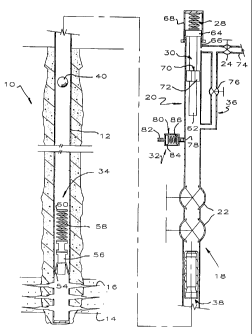
Referring to Figures 1-2, a hydrocarbon well 10 comprises a
production string 12 extending into the earth in communication with
a subterranean hydrocarbon bearing formation 14. The production
string 12 is typically a conventional tubing string made up of
joints of tubing that are threaded together. Although the
production string 12 may be inside a casing string (not shown), it
is illustrated as cemented in the earth. The formation 14
communicates with the inside of the production string 12 through
perforations 16. As will be more fully apparent hereinafter, the
plunger lift 18 may be used to lift oil, condensate or water from
the bottom of the well 10 which may be classified as either an oil
well or a gas well.
In a typical application of this invention, the well 10 is a
gas well that produces some formation liquid. In an earlier stage
of the productive life of the well 10, there is sufficient gas
being produced to deliver the formation liquids to the surface.
The well 10 is equipped with a conventional well head assembly 20
comprising a pair of master valves 22 and a wing valve 24 deliver-
ing produced formation products to a surface facility for separat-
ing, measuring and treating the produced products.
7
CA 02353733 2008-02-27
The plunger lift 18 of this invention comprises, as major
components, a piston 26, an upper bumper 28, a decoupler 30, a
catcher assembly 32, a lower bumper assembly 34 and a bypass 36
around the piston 26 when it is its uppermost position in the well
head assembly 20.
The piston 26 is of unusual design and is made in two pieces
which, comprising an upper sleeve 38 and a ball 40. The sleeve 38
comprises a tubular body 42 having a central passage 44, a fishing
lip 46 at the upper end thereof and an annular seating surface 48
at the lower end thereof sized to closely receive the ball 40. In
other words, the seating surface 48 is generally hemispherical and
has a radius of curvature matching that of the ball 40. The
seating surface 48 is preferably recessed or nested into the sleeve
38 so that a portion of the ball 40 projects beyond the end of the
sleeve 38. The main reason is that when the sleeve 38 contacts the
ball 40 at the bottom of the well, the ball 40 prevents the sleeve
38 from contacting the bumper spring and either damaging the sleeve
38 or the bumper spring. Preferably, about 20-25% of the ball
diameter projects below the sleeve 38.
The exterior of the sleeve 38 provides a seal arrangement 50
to minimize liquid on the outside of the sleeve 38 from bypassing
around the exterior of the sleeve 38. The seal arrangement 50 may
be of any suitable type, such as wire wound around the sleeve 38
providing a multiplicity of bristles or the like or may comprise a
series of simple grooves or indentations 52. The grooves 52 work
because they create a turbulent zone between the sleeve 38 and the
inside of the production string 12 thereby restricting liquid flow
on the outside of the sleeve 38. The grooves 52 are also used as
a catch area for a retriever to hold the sleeve 38 at a well head,
as will be more fully apparent hereinafter.
The ball 40 has a radius of curvature matching the seating
surface 48 and is, of course, of elegant simplicity. By suitably
8
CA 02353733 2001-07-25
machining the ball 40 and surface 48, no resilient seals or
additional seals of any type are necessary. In one practical
embodiment of the invention, the ball may be of polished chrome
steel having a Rockwell hardness of 48-52. The seating surface 48
is machined to a clean finish but preferably no special surface
preparation is done. After a few impacts with the ball 40, the
seating surface 48 assumes a desirable surface finish.
As will be more fully apparent hereinafter, the ball 40 is
first dropped into the well 10, followed by the sleeve 38. The
ball 40 and sleeve 38 accordingly fall separately and independently
into the well 10, usually while the well 10 is producing gas and
liquid up the production string 12 and through the well head
assembly 20. By separately, it is meant that the ball 40 and
sleeve 38 are not connected. By independently, it is meant that
the ball 48 and sleeve 38 are capable of moving independently of
one another even if they are tethered together in some fashion.
When the ball 40 and sleeve 38 reach the bottom of the well, they
nest together in preparation for moving upwardly.
In one aspect, the sleeve 38 and ball 40 each have a flow
bypass so they separately fall easily into the well 10 even when
there is substantial upward flow in the production string 12. When
they reach the bottom of the well, they unite into a single
component which substantially closes the flow bypasses, or at least
restricts them, so gas entering through the perforations 16 pushes
the piston 26 upwardly in the well and thereby pushes liquid, above
the piston 26, upwardly toward the well head assembly 20.
Looked at in another perspective, the sleeve 38 and ball 40
each have a surface area which is selected so that they separately
fall easily in the well but, when they are united into the piston
26, the piston 26 is pushed upwardly in the well thereby pushing
any liquid upwardly toward the well head assembly 20. The
selection of the surface areas of the sleeve 38 and ball 40 is
9
CA 02353733 2001-07-25
preferably done so that a given pressure differential will move the
ball 40 before moving the sleeve 38. In other words, the ball 40
is easier to move than the sleeve 38. The reason is that is if the
ball 40 can be constructed so it always pushes from below, there is
no tendency for the sleeve 38 to separate from the ball 40 during
upward movement in the well 10.
The upper bumper 28 is of conventional design and comprises a
helical spring. Bumpers of this type are well known in the plunger
lift art and are commercially available.
The lower bumper assembly 34 sits, or is part of, a conven-
tional collar stop 54 that is supported in the gap provided by
couplings between adjacent joints of the production string 12. In
a well (not shown) having a tubing string inside a casing string
cemented in the earth, the lower bumper assembly 34 typically sits
in a seating nipple (not shown) in the tubing string. The lower
bumper assembly 34 includes a body 56 and a relatively long,
preferably helical, spring 58 open at the top, i.e. without any
anvil so the spring 58 provides an opening to receive, or partially
receive the ball 40. Because the ball 40 falls into the bottom of
the well 10 when it is flowing, there is little or no liquid
accumulated adjacent the formation 14. Thus, the ball 40 tends to
strike the lower bumper 34 at higher velocities than conventional
plunger pistons. For this reason, a longer, softer bumper spring
is desired. Because the spring 58 is open upwardly, the ball 40
tends to be received in the open upper coil 60 so the ball 40 tends
to drop into the spring 58 and does not repeatedly bounce off and
rebang the spring 58, as would occur if the ball 40 were to strike
an anvil.
The decoupler 30 acts to separate the piston 26 when it
reaches the well head assembly 20. The decoupler 30 comprises a
rod 62 sized to pass into the top of the sleeve 38 and is fixed to
a piston 64. The piston 64 is larger than a conduit 66 in which
CA 02353733 2008-02-27
the rod 62 reciprocates and is thus prevented from falling into the
well 10. The top of the well head assembly 20 is closed with a
screw cap 68. A stop 70 on the rod 62 limits upward movement of
the sleeve 38. A series of grooves 72 allow formation products to
pass around the stop 70 and into a flow line 74 connected to the
wing valve 24. It will be seen that the piston 26 moves upwardly
in the well 10 as one piece. When the sleeve 38 passes onto the
end of the rod 62, the rod 62 ultimately contacts the top of the
ball 40, stopping upward movement of the ball 40 and allowing
continued upward movement of the sleeve 38. The end of the rod 62
below the stop 70 is longer than the passage 44 so the ball 40 is
pushed out of the sleeve 38 thereby releasing the ball 40 which
falls toward the bottom of the well 10.
The bypass 36 helps prevent the piston 26 from sticking in the
well head assembly 20 and may include a valve 76. The bypass 36
opens into the well head assembly 20 below the bottom of the sleeve
38 when it is in its uppermost position in the well head assembly
20. Thus, there will be a tendency of gas flowing through the well
head assembly 20 to move through the bypass 36 rather than pinning
the sleeve 38 against the stop 70.
A catcher 32 may be provided to latch onto the sleeve 38 and
thereby hold it for a while to provide a delay period between
successive cycles of the piston 26 in an attempt to match the cycle
rate of the piston 26 with the well 10 to remove produced formation
liquid as expeditiously as possible and thereby restrict gas
production as little as possible. To these ends, grooves 52 of the
sleeve 38 are sized to receive a ball detent 78 forced inwardly
into the path of the sleeve 38 by an air cylinder 80 connected to
a supply of compressed gas (not shown) through a fitting 82. A
piston 84 in the cylinder 80 is biased by a spring 86 to a position
releasing the ball detent 78 for movement out of engagement with
one of the slots 52. Pressure is normally applied to the cylinder
11
CA 02353733 2001-07-25
80 thereby forcing the ball detent 78 into the path of travel of
the sleeve 38. Upon a signal from a controller (not shown), gas
pressure is bled from the cylinder 80 allowing the spring 86 to
retract the piston 84 and allowing the weight of the sleeve 38 to
push the ball detent 78 out of the slot 52 thereby releasing the
sleeve 38 for movement downwardly into the well 10.
When it is desired to retrieve the ball 40 or the piston 26,
the decoupler 30 is replaced with a similar device having a stop 70
but eliminating the rod 62. This causes the piston 26 to impact
the bumper 28 without dislodging the ball 40. The piston 26 is
held in its upward position by the flow of formation products
around the piston 26 in conjunction with the catcher 32 which
latches onto the sleeve 38.
Operation of the plunger lift 18 of this invention should now
be apparent. The ball 40 is first dropped into the well 10. It
falls rapidly through a rising stream of produced products onto the
bumper assembly 34 which substantially cushions the impact and
minimizes damage to the ball 40 to a large extent because the top
of the spring 58 is open. When the sleeve 38 is released by the
catcher 32, it falls through the well 10 to the bottom. Because
ball 40 easily enters the bottom opening of the sleeve 38, the ball
40 and sleeve 38 easily unite with the ball 40 sealing against the
seating member 80. The combined downwardly surface area of the
sleeve 38 and ball 40, in their united configuration, is sufficient
to allow gaseous products from the formation 14 to push the piston
26, and any liquid above it, upwardly to the well head assembly 20.
As the piston 26 approaches the well head assembly 20, a slug
of liquid passes through the wing valve 24 into the flow line 74
toward a surface treatment facility. The sleeve 38 passes over the
rod 62 which stops upward movement of the ball 40 thereby releasing
the ball 40 which drops into the well 10 in the start of another
cycle. The sleeve 38 is retained by the catcher 32 for a period of
12
CA 02353733 2005-07-13
time depending on the requirements of the well 10. If the well 10
needs to be cycled as often as possible, the delay provided by the
catcher 30 is only long enough to be sure the ball 40 will reach
the bottom of the well 10 before the sleeve 38. In more normal
situations, the sleeve 38 will be retained on the catcher 30 so the
piston 26 cycles much less often.
A prototype of this invention has been tested. In a 5400' gas
well that loads up and dies with produced liquid, it took six and
one half minutes to make a round trip from the surface to 5400' and
return to the surface bringing approximately 1-4 barrel of gas cut
liquid. A delay of forty five minutes between dropping the sleeve
38 kept the well unloaded. Between plunger trips, the well
produced 310 MCF per day.
Pistons 26 having a chrome steel ball 40 and a sleeve 38 made
of 4140 heat treated steel have proved quite successful in a wide
variety of applications. Wells having very low bottom hole flowing
pressures, e.g. 75 psi, present an unusually tough situation for
any type plunger lift for a variety of reasons, almost all of which
relate to the fact that very little liquid will kill the well,
often in a way that is not readily apparent.
For purposes of illustration, it is assumed that a well has a
75 psi bottom hole flowing pressure and fifty feet of liquid in the
bottom of the hole above the perforations when the plunger piston
arrives. Using a normal plunger lift will kill the well because
shutting the well in to drop the piston will cause the liquid
flowing up the production string as a film on the inside of the
tubing string to fall to the bottom, producing a liquid column
sufficient to kill the well. In a two part plunger system of this
invention, or as disclosed in co-pending application S.N.2,301,791
the sleeve 38 may shear some of the liquid film off the inside
,of the production string and cause it to fall or be pushed by the
sleeve 38 toward the bottom of the well. When the sleeve 38
13
CA 02353733 2001-07-25
arrives at the bottom of the well 10, unites with the ball 40 and
starts up the hole in response to bottom hole flowing pressure
under the piston 26, it starts lifting the original liquid column
plus any liquid that has been sheared off during downward movement
of the sleeve 38 plus any liquid that is picked up during upward
movement of the piston. The liquid that is picked up during upward
movement of the piston may be substantial because, as the piston
starts upwardly, the gas velocity above the piston falls to almost
zero thereby allowing the film of liquid on the inside of the
production string to fall to the top of the piston. Because the
bottom hole flowing pressure is so low, it is easy to collect
enough liquid above the piston 26, when it is moving, to slow down
and stop the piston 26. When this occurs, the piston 26 ultimately
falls to the bottom of the well 10 and the well 10 is dead.
Thus, shearing liquid off the upwardly flowing film during
downward and then upward movement of the sleeve 38 creates an
additional liquid load for the piston 26. Recognizing this, among
other things, leads one to cycle the piston 26 much more frequently
to keep the production string 12 as free of liquid as possible.
This means the ball 40 and sleeve 38 are prone to arrive at the
bottom of the well 10 when there is no liquid column covering the
bumper assembly 34. Because any liquid column slows down the fall
of the ball 40 and sleeve 38, this means the ball 40 and sleeve 38
are falling at a very rapid rate when contacting the bumper spring
58.
The force delivered by, and to, the ball 40 and/or sleeve 38
is equal to the mass of the ball 40 and/or sleeve 38 multiplied by
the square of the velocity when they impact the spring 58. Thus,
lightening the ball 40 and/or sleeve 38 reduces the impact forces
acting on the bumper assembly 34, the ball 40 and the sleeve 38.
Manifestly, the ball 40 and sleeve 38 have to be strong to
withstand such impact forces, particularly when they are repeated
14
CA 02353733 2001-07-25
a number of times per hour. Aluminum alloys have not proved
successful even though they are much lighter than steel but they
are too soft and deform too easily.
It has been found that making the ball 40 and/or the sleeve 38
of titanium alloys provides desirably low weight to minimize impact
forces and desirably high strength to withstand the impact forces
generated during operation. Although densities of titanium alloys
are not widely available in the literature, the published density
of titanium is .16 pounds/cubic inch. Titanium alloys used in this
invention have densities less than about .25 pounds/cubic inch.
Light weight sleeves 38 and light weight balls 40 are important
because they reduce the impact forces occurring when the balls 40
and sleeves 38 collide at the bottom of the well as will be more
fully apparent hereinafter.
Because the requirement is for high strength and low weight,
which is characteristic of titanium alloys, there are many titanium
alloys that are operable in this invention. The important strength
characteristic is thought to be strength in compression. Compres-
sive strengths of titanium alloys are not easy to determine from
the literature or from suppliers but it is thought that tensile
strengths are a proxy for compressive strengths in the sense that
compressive strengths are of similar magnitude as tensile strengths
and compressive strengths rise as tensile strengths rise. For use
in this invention, a titanium alloy should have a tensile strength
of at least 90,000 psi and preferably above 115,000 psi. Although
there are many titanium alloys that fit this description, one that
has proved suitable is called 6AL4V titanium, meaning that it
contains about 6% aluminum and 4% vanadium with minor amounts of
other metals. A plunger piston of this invention has proved to
operate trouble free in very low flowing pressure wells for a
number of months where steel sleeves and balls have been damaged
CA 02353733 2001-07-25
beyond use within a short time from repeated impacts with the
bumper assembly 34.
Another suitable material for the ball 40 is silicon nitride
which is a proven material used in ball check valves. Silicon
nitride balls are very durable and somewhat lighter than titanium
alloys.
One unusual aspect of titanium plungers of this invention is
they take longer to cycle than substantially identical steel
plungers. For example, a well equipped with a steel plunger might
cycle in seven minutes, i.e. from the time the sleeve 38 is dropped
until the plunger 26 reappears at the well head 20. Equipping the
well with a titanium plunger increases the cycle significantly, for
example, to nine minutes. It is believed that the time increase
does not occur during upward movement of the plunger 26 in the well
but occurs during downward movement of the sleeve 38 and ball 40.
Without being bound by any particular theory, this is believed to
occur because of the interaction of upwardly flowing gas and
upwardly flowing liquid on the light weight sleeve 38 and light
weight ball 40. This is important because it means that a titanium
sleeve 38 and light weight ball 40 do not travel as fast downwardly
in the well as a comparable steel sleeve 38. This is important
because the force applied to the sleeve 38 and/or the ball 40 is
proportional to the mass of the element multiplied by the square of
its velocity. By using a strong, light weight sleeve 38 and ball
40, the impact forces between them and the bumper spring 58 is much
reduced.
Although this invention has been disclosed and described in
its preferred forms with a certain degree of particularity, it is
understood that the present disclosure of the preferred forms is
only by way of example and that numerous changes in the details of
construction and operation and in the combination and arrangement
16
CA 02353733 2001-07-25
of parts may be resorted to without departing from the spirit and
scope of the invention as hereinafter claimed.
17