Note: Descriptions are shown in the official language in which they were submitted.
CA 02353947 2001-06-05
WO 00/34120 PCT/US99/13694
1
Title: AUTONOMOUS STRATOSPHERIC AIRSHIP
Z . FT_Er_.D OF THE INVENTTnu
The present invention relates to the field of lighter
s than-air type craft and, more particularly, to an autonomous
stratospheric airship having a neutrally buoyant structure at
flight altitude, making use of regenerative electric energy
storage and collection. This application claims the benefit of
U.S. Provisional Patent Application Number 60/111,835, filed on
December 11, 1998 and U.S. Utility Patent Application Number
09/247,878, filed on February 15, 1999.
2. DESCRIPTION nF THE REr.ATFn n~T
In the past, there have been designed and used a series of
dirigibles, other types of lighter-than-air vehicles, hot-air
balloons, and so forth, for passenger transport, rescue work,
lift capabilities, and transport of goods and supplies. The
present invention relates to a powered airship having a buoyant
structure designed specifically for operations in the
stratosphere. It incorporates an autonomous navigation
capability and a regenerative solar electric energy collection
and storage system, enabling the airship to remain aloft for
extended periods of time, while following a specified course
and gathering mission-specific data.
The prior art reveals several attempts at providing a
portion of the capabilities embodied in the present invention,
but none was found to incorporate all of the capabilities
mentioned below and each such attempt tends to utilize rather
complicated mechanical structures. U.S. Patent Nos. 5,333,817
and 5,538,203 both disclose a buoyancy adjustment system for a
lighter-than-air vehicle, involving a series of ballonets, each
arranged along the longitudinal axis of the airship in equal
numbers. The object of these inventions is to provide a system
of independent control for ballonet inflation/deflation which
dispenses with ducted coupling to the individual ballonets. In
CA 02353947 2001-06-05
WO 00/34120 PCT/US99/13694
2
addition, U.S. Patent No. 5,538,203 provides rapid deflation of
the same ballonet system, instead of merely venting it to the
atmosphere. In either case, this system is rather primitive
and does not take into account the differential pressure
between the atmosphere, the surrounding airship gas bag, and
the pressure within individual ballonets.
U.S. Patent No. 5,348,254, issued to Nakada, claims an
airship design for flights of long duration powered by solar
cell batteries and a hydrogen generation system. This system
obviates the need for batteries by electrolytic generation of
hydrogen; however, accidental puncture of the hydrogen storage
envelope can easily result in complete destruction of the
airship.
U.S. Patent No. 4,995,572, issued to Piasecki, describes
a multi-stage, high-altitude data acquisition platform
comprising the combination of a low-altitude dirigible and a
stratospheric balloon for use at 60,000 ft. and above. The
primary object of this invention is to provide a stable launch
platform for lifting heavy payloads to stratospheric altitudes.
The airship contains a silo used to retain the stratospheric
balloon for launch from low altitudes. Such a multi-vehicle
payload lifting system is rather complex and unnecessary for
accomplishing the advantages and objectives of the present
invention.
U.S. Patent No. 4,204,656 issued to Seward III, discloses
a bi-axial propulsing control system for airships. This
system, as illustrated in the patent drawings, does not
distribute the propulsion motor loading equally among the
ascent/descent and left/right movement axes. In addition, the
torquing forces of the propulsion motor are applied at the ends
of the orientation axes, causing greatly increased loading on
the propulsion direction drive system.
French Patent No. 86 02734 discloses a dual-axis,
CA 02353947 2001-06-05
WO 00134120 PCT/US99/13b94
3
symmetric propulsion system for airships. This system
comprises a set of two or more motors which move in concert to
direct the motion of the airship. This application requires a
plurality of motors, unnecessary to implementation of the
present invention.
U.S. Patent No. 4,934,631, issued to Birbas, describes a
lighter-than-air vehicle comprising a framework surrounded by
a series of inflatable lift bags. Each bag contains a heating
element and lifting gas. The propulsion system comprises a
shrouded propeller with vanes to direct the propulsive force.
While this airship makes use of a single propulsion unit to
navigate through the air, it entails a complicated assembly
structure which is impractical for inexpensive construction.
In addition, the airship has no means of autonomous navigation
or maintaining station above a fixed point of the surface of
the earth in autonomous fashion.
Japanese Patent No. 5-221387A discloses an airship
constructed of transparent materials wherein a solar array is
disposed to receive energy from the sun. However, this design
is not constructed for multiple-axis array adjustment to
capture the maximum amount of solar energy based on the airship
position in relation to the sun. Only a single, longitudinal,
axis of rotation for the array is shown. Other patents, such
as Japanese Patent No. 54-35994, U.S. Patent No. 5,518,205
issued to Wurst et al., and U.S. Patent No. 4,364,532 issued to
Stark, all describe solar-powered airships with solar cells
disposed on the surface structure of the ship. Again, the
inherent disposition of the cell structure precludes the use of
optimal positioning of the cells to capture the maximum amount
of solar energy to be gained given a varied position of the
airship in relation to the sun.
None of the aforementioned inventions are directed toward
an autonomous platform specifically designed for flight in the
CA 02353947 2001-06-05
WO 00/34120 PCTNS99/13694
4
lower stratosphere. In addition, none are directed toward an
airship which is capable of controlling operational altitude,
including maintenance of a fixed position over a point on the
surface of the earth, or navigation between predetermined
waypoints. Further, none of the prior art is directed toward
an autonomous airship having a specially constructed solar
array energy extraction source which provides sufficient energy
for power during the day, and stores sufficient energy for
continuous night-time operation.
Therefore, it is desirable to have an autonomous airship
specifically designed for flight in the lower stratosphere,
with the ability to maintain a fixed position over a point on
the surface of the earth, or navigate between predetermined
waypoints. Additionally, it is desirable to have an autonomous
airship capable of controlling its operational altitude, using
ballonets to control the pitch axis attitude. Furthermore, it
is desirable to have an autonomous airship which uses a single
motor for propulsion that evenly distributes the propulsive
forces along the directive axes of the articulating means. It
is also desirable to have an autonomous airship which can
utilize solar energy to power propulsion during the day and
additionally, store sufficient energy for continuous operation
throughout the night.
SUMMARY OF THE INVENTION
In accordance with one aspect of the present invention, an
autonomous airship designed specifically for flight in the
lower stratosphere with the capability for maintaining a fixed
position over a point on the surface of the earth is disclosed.
Additionally, the airship provides autonomous control and
navigation between predetermined waypoints, or may be
programmed to remain within the optical line of sight of a
predetermined position on the surface of the earth by matching
the speed of the wind.
CA 02353947 2001-06-05
WO 00/34120 PCT/US99/13694
Other features of the airship embodying the present
invention include construction from high strength, light-
weight, polymer-based film materials for strength, and
transparent/translucent material for collection of solar energy
5 by internally-mounted solar arrays. The autonomous airship can
be launched in an uninflated condition and does not require
control or propulsion during ascent. The internally mounted
arrays reduce aerodynamic drag, provide a pointing capability
for maximum solar energy collection, are cooled by an air duct,
and are contained within a separate chamber which permits
access to the arrays from the outside of the airship.
The airship embodying the present invention may include a
hull defining an enclosed cavity, a lifting gas, a forward
ballonet, an aft ballonet, and an equipment bay disposed within
the cavity, the bay defining an enclosed chamber, and an
overall air management subsystem, at least one solar array, a
multiplicity of energy storage units, and an autonomous control
system disposed within the bay, the chamber being in fluid
communication with the forward and aft ballonets; a propulsion
system attached to the hull and in electrical communication
with at least one solar array and the energy storage units; and
a multiplicity of tail fins attached to the hull. The air
management subsystem may further comprise a forward air
management subsystem having a blower and an aft air management
subsystem, the forward air management subsystem being in fluid
communication with the forward ballonet and the bay, and the
aft air management subsystem being in fluid communication with
the aft ballonet and the bay. The forward air management
subsystem may comprise a forward ballonet pressure sensor and
the aft air management subsystem may comprise an aft ballonet
pressure sensor. The forward and aft air management subsystems
may also each comprise a lifting gas release valve, the valves
being in fluid communication with the hull.
CA 02353947 2001-06-05
WO 00/34120 PCT/US99/13694
6
The propulsion system of the present invention may
further comprise a gimbal housing, a motor and transmission
assembly, a motor pivot, and a propeller, the housing being
fixedly attached to the hull and pivotally mounted to the
pivot, the pivot being fixedly attached to the motor and
transmission assembly, the assembly being attached to the
propeller.
At least one solar array may be aligned with the central
axis of the hull, and may be gimballed about respective
elevation and azimuth axes of the array. At least one solar
array may provide electrical power to the propulsion system
during daytime flight operations and the multiplicity of energy
storage units may provide electrical power to the propulsion
system during night time flight operations.
The autonomous control system of the present invention,
the overall air management subsystem, and the propulsion
system may provide navigational control between selected
waypoints, wherein the autonomous control system may include a
GPS receiver and a compass. Therefore, the overall air
management subsystem, the autonomous control system, and the
propulsion system may be adapted to control movement of the
airship about its center of gravity.
The hull of the present invention may have an outer
surface and a multiplicity of tail fins may be disposed in a
first position contiguous with the outer surface of the hull
during ascent to flight altitude and the multiplicity of tail
fins may move to a second position non-contiguous with the
surface of the hull as the hull inflates due to a reduction in
atmospheric pressure.
The present invention may also include, as an alternative
embodiment, a hull defining an enclosed cavity; a lifting gas
and at least one solar array disposed within the cavity; a
forward ballast reservoir; an aft ballast reservoir; a ballast
CA 02353947 2001-06-05
WO 00/34120 PCT/US99/13694
7
management subsystem attached to the hull and in fluid
communication with the forward and aft ballast reservoirs; an
equipment bay attached to the hull, the bay having a
multiplicity of energy storage units and an autonomous control
system; a propulsion system attached to the hull and in
electrical communication with at least one solar array and the
energy storage units; and a multiplicity of tail fins attached
to the hull. The ballast management subsystem may further
comprise fluid lines between the forward and aft ballast
reservoirs, a ballast valve, and a ballast exhaust.
The alternative embodiment airship propulsion system of
the present invention may further comprise a gimbal housing, a
motor and transmission assembly, a motor pivot, and a
propeller, the housing being fixedly attached to the hull and
pivotally mounted to a pivot, the pivot being fixedly attached
to a motor and transmission assembly, the assembly being
attached to the propeller.
In this alternative embodiment at least one solar array
may be aligned with a central axis of the hull, and the array
may be gimballed about respective elevation and azimuth axes of
the array. At least one solar array may provide electrical
power to the propulsion system during daytime flight operations
and the multiplicity of energy storage units may provide
electrical power to the propulsion system during night time
flight operations.
The autonomous control system, the ballast management
subsystem, and the propulsion system in this alternative
embodiment of the present invention may provide navigational
control between selected waypoints, wherein the autonomous
control system may include a GPS receiver and a compass.
Therefore, the ballast management subsystem, the autonomous
control system, and the propulsion system may be adapted to
control movement of the airship about its pitch and yaw axes.
CA 02353947 2001-06-05
WO 00/34120 PCT/US99/13694
8
The hull in the alternative embodiment of the present
invention may have an outer surface and a multiplicity of tail
fins may be disposed contiguous with the outer surface of the
hull during ascent to flight altitude, wherein the multiplicity
of tail fins may move to a second position non-contiguous with
the surface of the hull as the hull inflates due to a reduction
in atmospheric pressure.
BRIEF DESCRTPTION OF THE DRAWINC~B
FIG. 1 is a side view of a first embodiment of the
autonomous airship of the present invention.
FIG. 2 is a schematic block diagram of the pressurization
system for the ballonets within the first embodiment.
FIG. 3 is a side view of a forward ballonet air management
subsystem.
FIG. 4 is a side view of an aft ballonet air management
subsystem.
FIG. 5 is a perspective view of the propulsion system for
an airship.
FIG. 6 is a side view of the equipment bay assembly for
the first embodiment.
FIGS. 7A and 7B are perspective views of one of the
internally-mounted solar array panels which provide electric
power to the first embodiment.
FIG. 8 is a schematic block diagram of the power supply
system for the first embodiment.
FIG. 9 is a block diagram of the controller interface
circuitry for directing autonomous airship operations.
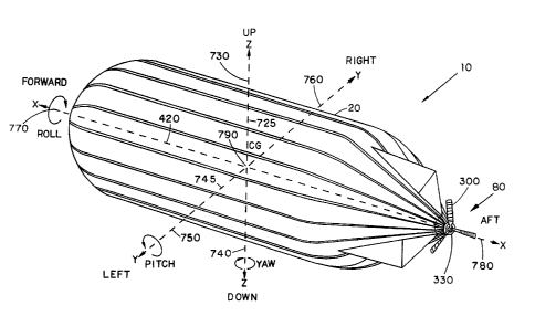
FIG. 10 is a perspective view of an airship illustrating
various movement axes.
FIG. 11 is a side view of a second, alternative embodiment
of the autonomous airship of the present invention.
FIG. 12 is a schematic view of the ballast management
subsystem for a second, alternative embodiment of the
CA 02353947 2001-06-05
WO 00/34120 PCT/US99/13694
9
autonomous airship of the present invention.
FIG. 13 is a perspective view of the rectangular solar
array assembly for a second, alternative embodiment of the
autonomous airship of the present invention.
FIG. 14 is a schematic block diagram of the power supply
subsystem for a second, alternative embodiment of autonomous
airship of the present invention.
DESCRIPTION OF THE PREFERRED EMBODIMENT
Turning now to FIG. 1, a side view of the first embodiment
of the autonomous stratospheric airship 10 can be seen. The
hull 20 is made from a clear or relatively transparent polymer
based film, preferably 0.5 mm thick. The material is selected
to withstand pressures resulting from changes in lifting gas
temperatures contained within. The hull 20 is shaped as a
stream-lined body with a hemispherical front and a conical
rear, and the overall size is determined by the mass of the
payload 390, while the length to width ratio is preferably 5:1.
As the result of experimentation, it has been found that a
design capable of carrying 18 pounds of useful load to 70,000
feet is approximately 125 feet long, and 25 feet in diameter.
Attached to the conical section of the hull 20 are a
multiplicity of self-deployed tail fins 90, preferably three in
number. The fins 90 are preferably made of the same film
material as the hull 20. The fins 90 are supported by a self
erecting mechanism that deploys as the hull 20 body inflates
during ascent. The hull 20 center of buoyancy is controlled by
two internal ballonets, forward ballonet 40 and aft ballonet
50. Each ballonet can be used independently to control the
location of the center of buoyancy, consequently effecting the
airship's 10 movement about the pitch axis 745 (see FIG. 10).
Alternatively, the ballonets 40 and 50 can be used together to
cause the airship 10 to ascend or descend.
CA 02353947 2001-06-05
WO 00/34120 PCTNS99/13694
The airship 10 completely encloses an internal equipment
bay 30 chamber which houses solar arrays 340, forward and aft
air management sub-systems 60 and 70, a control system 390, and
a mission-specific payload. While the hull 20 is filled with
5 lifting gas comprising hydrogen, helium, or ammonia, the bay 30
is filled with air drawn from the atmosphere outside of hull 20
and is circulated within the bay 30 for cooling of internal
components. The bay 30 can also be pressurized and so function
as an additional buoyancy control mechanism for airship 10. To
10 maintain the integrity of hull 20, the contents of bay 30 can
be accessed from the exterior of airship 10 by means of a
zipper, zip-lock plastic closure or other relatively air-tight
closure (not shown).
FIG. 2 depicts a schematic block diagram of the
pressurization system used to control the air flow and
pressurization of the equipment bay 30 and the forward and aft
ballonets 40 and 50. Forward ballonet 40 is connected to
forward ballonet valve 160 by way of forward ballonet fill-tube
162. Forward ballonet pressure sensor 110 is used to monitor
the pressure differential between the forward ballonet 40 and
the lifting gas pressure within hull 20. Forward ballonet
valve 160 is also connected to the atmosphere within the
equipment bay 30 by way of forward ballonet equipment bay
intake 164. Forward ballonet 40 may exhaust air to the
atmosphere external to the hull 20 by means of forward ballonet
atmospheric exhaust 166. Thus, forward ballonet 40 may take in
air from the atmosphere surrounding hull 20 by way of forward
ballonet equipment bay intake 164, or exhaust air to the
atmosphere surrounding hull 20 by way of forward ballanet
atmospheric exhaust 166.
Similarly, rear ballonet 50 is connected to aft ballonet
valve 210 by way of aft ballonet fill tube 212. The
differential pressure between the aft ballonet 50 and the
CA 02353947 2001-06-05
WO 00/34120 PCT/US99/13694
11
lifting gas within hull 20 is measured by aft ballonet pressure
sensor 150. Aft ballonet 50 operates in a manner similar to
forward ballonet 40; that is, aft ballonet 50 may take in air
from the atmosphere surrounding hull 20 by way of aft ballonet
equipment bay intake 214, and may exhaust air to the atmosphere
surrounding hull 120 by way of aft ballonet atmospheric exhaust
216.
The physical implementation of the airship 10 air
management sub-system is illustrated in FIGS. 3 and 4. FIG. 3
depicts a side view of the forward air management sub-system
60, and FTG. 4 depicts a side view of the aft air management
sub-system 70. Turning now to FIG. 3, it can be seen that the
forward air management sub-system 60 provides a housing for the
forward ballonet valve 160, forward ballonet pressure sensor
110, equipment bay pressure sensor 120, hull pressure sensor
130, and blower motor 230. Forward air management sub-system
60 also incorporates a scoop 220 to further assist in air flow
control.
During normal operations, the blower motor 230 will take
in air from the atmosphere surrounding hull 20 via scoop 220
and pressurize the equipment bay 30 by means of equipment bay
atmospheric intake 235 and check valve 240, which prevents
release of pressurized air from equipment bay 30 back into the
atmosphere. The pressure within the hull 20 is monitored by
hull pressure sensor 130. In order to pressurize the forward
ballonet 40 so as to pitch the airship 10 downward or cause the
airship 10 to descend (assuming a similar action by aft air
management sub-system 70), the forward ballonet valve 160 is
operated so as to direct pressurized air from the equipment bay
30, through forward ballonet equipment bay intake 164 to the
forward ballonet 40 by way of forward ballonet fill tube 162.
If it is desired to pitch the airship 10 upward or to ascend
(assuming a similar action conducted with aft air management
CA 02353947 2001-06-05
WO 00/34120 PCT/US99/13694
12
sub-system 70), the forward ballonet valve 160 can be operated
so as to exhaust the forward ballonet 40 air by way of the
forward ballonet fill tube 162 and the forward ballonet
atmospheric exhaust 166 port into the atmosphere surrounding
the hull 20 by way of scoop 220. The operation of scoop 220 is
controlled by scoop actuator 250. If the pressure within the
equipment bay 30 and forward ballonet 40 are as desired for a
given flight attitude and altitude, then the forward ballonet
valve 160 can be operated so as to close off the forward
ballonet fill tube 162 and prevent the escape of any air from
the forward ballonet 40. As a safety measure, hull pressure
sensor 130 is used to monitor the lifting gas pressure exerted
within hull 20 and can be used to activate a lifting gas relief
valve 260 by way of a lifting gas release actuator 270 so as to
dump lifting gas to the atmosphere and relieve any over-
pressure situation within the hull 20.
Turning now to FIG. 4, it can be seem that aft air
management sub-system 70 is identical to forward air management
sub-system 60, with the exception of the sensors housed
therein, the blower motor 230, and its associated check valve
240. Atmospheric pressure sensor 140 is housed in the aft air
management sub-system 70 enclosure, along with the aft ballonet
pressure sensor 150. Inflation and deflation of the aft
ballonet 50 occurs in a similar fashion to that of forward
ballonet 40, except that air for the aft ballonet 50 is taken
directly from the equipment bay 30, and is supplied from the
blower motor 230 located in the forward air management sub-
system 60. That is, the aft ballonet 50 is inflated by
operation of the aft ballonet valve 210 so as to create a path
between the aft ballonet equipment bay intake 214 and the aft
ballonet fill tube 212. The aft ballonet 50 is deflated by
operating the aft ballonet valve 210 so as to create a path
between the aft ballonet fill tube 212 and the aft ballonet
CA 02353947 2001-06-05
WO 00/34120 PCTNS99/13694
13
atmospheric exhaust 216. The scoop 220 on the aft air
management sub-system 70 can likewise be operated to assist in
exhausting air from the aft ballonet 50.
The aft air management sub-system 70 also has the
capability of depressurizing the hull 20 by activating a
lifting gas relief valve 260 by means of lifting gas release
valve actuator 270. By operating the aft ballonet valve 210 so
as to create a path between the equipment bay intake 214 and
the equipment bay outlet valve 200, it is also possible to
exhaust air from the equipment bay 30 into the atmosphere
surrounding the hull 20.
The airship 10 is propelled by a propulsion system 80
comprising a propeller 300, driven by a motor and transmission
assembly 330, as shown in FIG. 5. Left and right directional
control of the airship 10 is provided by moving the motor and
transmission assembly 330 about the axis of the motor pivot
320, which is mounted within the gimbal housing 310. The
propeller 300 is preferably a three-bladed fixed-pitch type,
but a variable-pitch type propeller 300 may be used without
detracting from the spirit of the invention. Those skilled in
the art will readily recognize the advantages and disadvantages
involved in choosing between these two types of propellers.
FIG. 5 also illustrates the tail fins 90 of the airship
10, which are used to enhance in-flight stability about the
pitch axis 745, yaw axis 725, and the hull central axis (or
roll axis) 420 of the airship 10 (see FIG. 10). Tail fins 90
are most preferably three in number, and each comprise a
pivoting mast 305 connected to a fin pivot 307. This manner of
construction allows each of the tail fins 90 to lay along the
surface of the hull 20 of the airship 10 during initial launch
and, as the hull 20 begins to expand due to the decrease in
atmospheric pressure surrounding it, the tail fins 90 will
deploy into their extended position away from hull 20 (as
CA 02353947 2001-06-05
WO 00/34120 PCT/US99/13694
14
illustrated in FIG. 5) due to the rotation of the mast 305.
FIG. 6 illustrates the equipment bay 30 and its contents
comprising internally-gimballed solar arrays 340, energy
storage units 350, emergency system 360, autonomous control
system 390, communications system 380, and the emission
specific payload 370. As mentioned previously, the forward and
aft air management sub-systems 60 and 70 can be used to
pressurize and exhaust the equipment bay 30. In addition, the
constant induction of air by way of forward air management sub-
system 60 into equipment bay 30 can be used to cool the
contents of equipment bay 30, especially solar arrays 340.
Pressurizing the equipment bay 30 with air from the atmosphere
surrounding hull 20 also serves as an additional buoyance
control mechanism for the airship 10.
All of the energy used to power the propulsion system 80
is provided by the solar arrays 340. During the day, solar
energy can be directly applied to the propulsion system 80,
while night time energy is supplied by energy storage units
350, preferably deep-cycle batteries well known in the art,
which are charged by the solar arrays 340 during the day.
The solar energy collection system consists of a
multiplicity of arrays 340 that are installed within the
equipment bay 30, which is located within the hull 20. As
shown in FIGS. 7a and 7b, the arrays 340 are mounted on
gimbals, denoted as azimuth rotation pivot 400 and elevation
rotation pivot 410. These two axes of rotation, combined with
the orientation of the arrays 340 along the hull central axis
420, allow pointing the solar array 340 panels to obtain
maximum collection efficiency, regardless of the position of
the airship 10 with respect to the sun. Internally mounting
arrays 340 permit operation of the airship 10 without the
associated aerodynamic drag of externally mounted solar panels.
In addition, the construction of the airship 10 makes it
CA 02353947 2001-06-05
WO 00/34120 PCTNS99/13694
possible to duct cooling air around the arrays 340 and other
contents of the equipment bay 30 without breaching the
integrity of the main hull 20, which also serves as the main
lifting gas chamber. The equipment bay 30 is equipped with any
5 of several closures well known in the art, such as zippers or
plastic zip-lock devices (not shown) which provide direct
access through the equipment bay 30 for installation servicing
of the equipment at any time prior to launch, without affecting
the integrity of the hull 20. The transparency or translucency
10 of the hull 20 can be varied to affect the amount of solar
energy collected by the arrays 340.
Turning now to FIG. 8, the components for the energy
provision and storage system for the airship 10 can be seen.
Each solar array 340 is moved about its azimuth rotation pivot
15 400 by means of an azimuth motor 450, which is directed by an
azimuth controller 440, and powered by an azimuth power source
430, derived from energy storage units 350 distributed
throughout the equipment bay 30. Similarly, the arrays 340 are
moved about their elevation rotation pivots 410 by an elevation
motor 510, which is directed by an elevation controller 500 and
powered by an elevation power source 490, also derived from
energy storage units 350.
The activity of azimuth controller 440 is effected by the
azimuth measurements derived from the azimuth feedback signal
480, provided by the azimuth transducer 460. Similarly, the
activity of elevation controller 500 is influenced by the
elevation feedback signal 540 provided by the elevation
transducer 520. Both the azimuth and elevation controllers 440
and 500 are programmed to operate by way of proportional,
integral, or derivative control, or some combination of these
methods, as is well known in the art. Other feedback-based
control systems are also anticipated by the present invention.
During the day, solar arrays 340 are connected so as to
CA 02353947 2001-06-05
WO 00/34120 PCT/US99/13694
16
provide a relatively high motor drive voltage to the day drive
service bus 630, preferably about 136 volts DC. The solar
array current 610 and solar array voltage 620 are monitored by
the autonomous control system 390 (not shown). Step down
converter 645 operates to supply a battery charger/monitor 650
with sufficient current to charge the energy storage units 350
during daytime operations. Energy storage units 350, which may
consist of lithium-ion batteries, or other sources of storage
well known in the art, are monitored with respect to several
parameters, including battery voltage 670, battery current 690,
and battery temperature 700. If necessary, battery heaters 660
can be activated to bring the energy storage units up to a
predetermined charging or operational temperature for a maximum
efficiency. The monitored parameters are communicated to the
autonomous control system 390 and communications system 380 by
way of a control communication interface 680.
During nighttime operations, the propulsion system 80 is
powered by way of night drive service bus 640. The night drive
voltage 550, night drive current 560 and converter temperature
570 are also monitored. The resulting data is also
communicated to the autonomous control system 390 and
communication system 380.
The voltage derived from the step-down converter 645 and
used to energize the night drive service bus 640 and the
battery charger/monitor 650, can be further reduced by way of
step-down converters 720, and used to power various payload 370
requirements. A standard avionics power bus, namely, ship
service bus 710, provides a standardized DC voltage to the
contents of the equipment bay 30. The ship service bus 710 is
preferably operated at a voltage of 28 volts DC.
An array temperature transducer 600, powered by a
transducer power module 590 is used to determined the
temperature of the solar arrays by way of an array temperature
CA 02353947 2001-06-05
WO 00/34120 PCT/US99/13694
17
transducer 580. If the arrays 340 exceed some pre-determined
temperature, then the forward and aft air management sub-
systems 60 and 70 can be activated to cool the arrays 340 to a
desired temperature. The array temperature monitoring
activity, as well as the cooling activity are directed by the
autonomous control system 390.
FIG. 9 illustrates a block diagram of the autonomous
control system 390. While preferably implemented with a
central processor 800 which communicates via a multiplicity of
serial channels 810 and an analog-to-digital converter 815.
However, specialized and more complex interfaces, such as may
be utilized by the airship 10 energy storage system, the front
and rear air management sub-systems 60 and 70, and the
propulsion system 80, may be specially constructed and
implemented as a solar cell and battery interface 860, a front
air management sub-system interface 870, a rear air management
sub-system interface 880, and a propulsion interface 890.
Payload interface 900 will normally be specially constructed to
interface to whatever mission-specific payload 370 is carried
by the airship 10. A Global Positioning System satellite (GPS)
receiver 820, electronic compass 830, command/control receiver
840, and telemetry transmitter 850 are also employed by the
airship 10 to complete the autonomous control function.
Included within the capabilities of airship 10 is the
transmission of acquired data from the various transducers and
sensors on board airship 10, and the payload 370.
Command/control receiver 840 enables the reception of
operational and emergency instructions from the ground control
station (not shown) which monitors the progress of the airship
10 on any specific mission. The GPS receiver 820 enables exact
positional monitoring and control of the airship 10, while the
electronic compass 830 provides for dead-reckoning capability
during periods where the GPS receiver 820 is incapable of
CA 02353947 2001-06-05
WO 00/34120 PCT/US99/13694
18
proper function. The autonomous control system 390, combined
with the operation of the air management sub-systems 60 and 70,
and the propulsion system 80, provide an airship 10 capable of
autonomous operation between pre-selected or commanded
waypoints. The internally-gimballed solar arrays 340 can be
pointed for maximum collection efficiency based on geographical
location, date, and time. Command control and data reception
can also be interactively applied to the payload 390.
The autonomous control system can be programmed to select
different speeds for day and night operations to maintain the
average location of the airship 10 over a specified point on
the surface of the earth. Properly selected, the speed
schedule selected for airship 10 will optimize use of the solar
arrays 340 and the energy storage units 350 to maximize the
average speed of the airship 10. When the prevailing winds are
less than the maximum airship 10 design speed, excess power is
available to reposition the airship 10 with respect to the
pitch axis 745, yaw axis 725, and the hull central axis 420, as
illustrated in FIG. 10.
The propulsion system 80 propels the airship 10 with
forward movement 770 as long as the electric power available to
the motor and transmission assembly 330 is great enough to
overcome the prevailing winds, less power (or no power) can
also be applied to the motor and transmission 330 so that
airship 10 in fact travels with aft movement 780. By moving
the motor and transmission assembly 330 about the axis of motor
pivot 320, the line of propulsion for the propeller 300 can be
moved so as to effect left movement 750 or right movement 760
of the airship 10. As mentioned previously, the forward and
aft ballonets 40 and 50 can also be pressurized independently
so as to cause downward movement 740 (if both are pressurized),
or upward movement 730 (if both are deflated). The
sophisticated combination of autonomous control system 390,
CA 02353947 2001-06-05
WO 00/34120 PCTNS99/13694
19
combined with the actions of the forward and aft air management
sub-system 60 and 70, and the motor pivot 320 of the propulsion
system 80, provide an airship 10 which is completely
controllable about the airship's center of gravity 790.
The autonomous stratospheric airship 10 can be used for
many different applications, including provision of a vehicle
platform for: large terrestrial viewing areas with a long
flight duration (e. g, exoatmospheric research); communication
relay operations (e. g. radio frequency transponder for voice,
data, video etc.; store and forward RF data; signal
interception; or direct broadcast); a terrestrial surveillance
platform with camera and sensors; surveillance of the
atmosphere or space; and a platform for scientific and
atmospheric research.
The autonomous stratospheric airship 10 is designed to be
a neutrally buoyant structure designed specifically for
operations in the lower stratosphere (i.e. 60,000-100,000 feet)
it does not require aerodynamic lift, and the hull 20 can be
filled with any gas that is lighter than air, including
hydrogen, helium, or ammonia. Use of a thin polymeric hull
material allows inexpensive and light-weight construction of a
hull 20 which is able to contain the lifting gas pressure while
isolating the equipment bay 30 from the surrounding atmosphere.
The airship 10 can be launched and climbs to altitude much in
the same way as a scientific superpressure balloon, and no
control or propulsion is required to effect such a launch. The
solar regenerative electric energy collection and storage
system provides propulsion during the day and night, and
continuous operation of powered payloads 370. Internally-
gimballed solar arrays 340 can be positioned for optimal
collection efficiency while having no effect on the aerodynamic
profile of the airship 10.
As a way of significantly reducing the cost of providing
CA 02353947 2001-06-05
WO 00/34120 PCT/US99/13694
an autonomous stratospheric airship 10, an alternative
embodiment, as shown in Fig. 11, is provided by the instant
invention. While the size and materials for construction of
the hull 20 are identical to the embodiment pictured in Fig. 1,
5 in this case, the equipment bay 30~ is located on the exterior
of the hull 20, and suspended from the interior of the hull 20
by payload suspension lines 905. While a single rectangular
array assembly 910 is maintained within the hull 20 for
providing operative energy to the airship 10 during the day,
10 the forward and aft ballonets 40 and 50, along with the forward
and aft air management subsystems 70 are no longer used.
However, the propulsion system 80, along with the self-erecting
tail fins 90, are retained.
Turning now to Fig. 12, the fluid ballast system 930 can
15 be seen. This simplified ballast system, while not providing
the capability of the previous embodiment with respect to
altitude control, still enables adjusting the attitude about
the pitch axis 745, as well as in the upward movement 730
direction.
20 The fluid ballast system 930 comprises a forward ballast
reservoir 931, filled with forward fluid ballast 932, connected
by way of fluid lines 936 to aft ballast reservoir 933, filled
with aft fluid ballast 934. Forward and aft fluid ballasts 932
and 934 are moved back and forth by way of by-directional pumps
940 and fluid lines 936, whenever ballast valve 938 is open so
as to provide fluid communication between forward ballast
reservoir 931 and aft ballast reservoir 933. To move airship
10 in the upward movement 730 direction, the ballast valve of
938 can be opened so as to provide fluid communication between
forward ballast reservoir 931 and ballast exhaust 942, or aft
ballast reservoir 933 and ballast exhaust 942. While a limited
amount of directional control is possible in a downward
movement 740 direction, it can only be achieved at the expense
CA 02353947 2001-06-05
WO 00/34120 PCT/US99113694
21
of draining helium from the hull 20 by way of a helium release
valve 928. Extra helium may be carried in a canister in the
equipment bay 30, but such operation is not usually practical,
due to payload weight limitations.
Fig. 13 details the rectangular array assembly 910, which
comprises a rectangular solar array suspended between a Z-axis
swivel 913 and a Z-axis drive arm 915 by means of array
suspension lines 914. The rectangular solar array 912 is held
at two corners between the Y-axis drive 925 and the Y-axis
bearing 926, so as to pivot about the elevation rotation axis
922. Similarly, the rectangular solar array 912 can be made to
pivot about the azimuth rotation axis 924 by driving the Z-axis
drive arm 915 with the Z-axis drive 916. Vertical movement of
the rectangular solar array 912, due to flexing of the hull 20,
is accommodated by the link arm 918, which allows the Z-axis
drive 916 and the feed-through and mount 920 to move freely.
By providing for movement in both the elevation rotation axis
920 and the azimuth rotation axis 924, the rectangular solar
array 912 can be positioned in whatever location is most
effective for receiving the maximum amount of solar energy for
conversion into electricity. The suspension system shown
allows construction of the rectangular array assembly 910 to
be lighter and less expensive than that used for the solar
arrays 340 illustrated in Figs. 7A and 7B. In fact, the
rectangular solar array 912 can even be applied to an
inflatable structure, which becomes rigid at flight altitude,
and is flexible on the ground.
Fig. 14 illustrates the power distribution subsystem 950
contained in the external equipment bay 30~ utilized by the
alternative embodiment of the airship 10. In this case, the
rectangular solar array 912 provides power to the motor
controller 954 by way of a high voltage bus 956. An
alternative source of power on this bus 956 are battery packs
CA 02353947 2001-06-05
WO 00/34120 PCT/US99/13694
22
964. The rectangular solar array 912 also provides power to an
18 VDC converter 958, which in turn energizes a charger 962 for
the battery packs 964, and provides power to the system
electronics 970 by way of a low-voltage bus 960. The system
electronics 970 in this case can be similar to or identical to
the arrangement disclosed in Fig. 9, less the front and rear
air management subsystem interfaces 870 and 880. Instead, a
single interface to the fluid ballast system 930 must be
implemented to control the bi-directional pumps 940 and the
ballast valve 938.
Although the invention has been described with reference
to specific embodiments, this description is not meant to be
constructed in a limited sense. Various modifications of the
disclosed embodiments, as well as alternative embodiments of
the invention will become apparent to persons skilled in the
art upon reference to the disclosure herein. It is, therefore,
contemplated that the appended claims will cover such
modifications that fall within the scope of the invention.
CA 02353947 2001-06-05
TECHSOURCE-FOLDER TAB SHEET
CLM-IP
CLAIMS SECTION
TEMP-ID: -
Registered & Indexed by: Date:
Scanned by: Date:
CA 02353947 2001-06-05
WO 00/34120 PCT/US99/13694
23
CLAIMS
We Claim:
1 1. An autonomous stratospheric airship comprising:
2 a hull defining an enclosed cavity, a lifting gas, a
3 forward ballonet, an aft ballonet, and an equipment bay
4 disposed within said cavity, said bay defining an enclosed
chamber, and an overall air management subsystem, at least one
6 solar array, a multiplicity of energy storage units, and an
7 autonomous control system disposed within said bay, said
8 chamber being in fluid communication with said forward and aft
9 ballonets;
a propulsion system attached to said hull and in
11 electrical communication with said at least one solar array and
12 said energy storage units; and
13 a multiplicity of tail fins, said fins attached to said
14 hull.
1 2. The airship of Claim 1 wherein said overall air
2 management subsystem further comprises a forward air management
3 subsystem having a blower and an aft air management subsystem,
4 said forward air management subsystem being in fluid
5 communication with said forward ballonet and said bay, and said
6 aft air management subsystem being in fluid communication with
7 said aft ballonet and said bay.
1 3. The airship of Claim 2 wherein said forward air
2 management subsystem further comprises a forward ballonet
3 pressure sensor and said aft air management subsystem further
4 comprises an aft ballonet pressure sensor.
1 4. The airship of Claim 2 wherein said forward and aft
2 air management subsystems each comprises a lifting gas release
3 valve, said valves being in fluid communication with said hull.
CA 02353947 2001-06-05
WO 00/34120 PCTNS99/13694
24
1 5. The airship of Claim 1 wherein said propulsion system
2 further comprises a gimbal housing, a motor and transmission
3 assembly, a motor pivot, and a propeller, said housing being
4 fixedly attached to said hull and pivotally mounted to said
pivot, said pivot being fixedly attached to said motor and
6 transmission assembly, said assembly being attached to said
7 propeller.
1 6. The airship of Claim 1 wherein said at least one
2 solar array is aligned with the central axis of said hull, and
3 is gimballed about respective elevation and azimuth axes of
4 said array.
1 7. The airship of Claim 1 wherein said at least one
2 solar array provides electrical power to said propulsion system
3 during daytime flight operations and said multiplicity of
4 energy storage units provide electrical power to said
5 propulsion system during night time flight operations.
1 8. The airship of Claim 1 wherein said autonomous
2 control system, said overall air management subsystem, and said
3 propulsion system provide navigational control between selected
4 waypoints.
1 9. The airship of Claim 1 wherein said autonomous
2 control system includes a GPS receiver.
1 10. The airship of Claim 1 wherein said autonomous
2 control system includes a compass.
1 11. The airship of Claim 1 wherein said overall air
2 management subsystem, said autonomous control system, and said
CA 02353947 2001-06-05
WO 00/34120 PCT/US99/13694
1 propulsion system are adapted to control movement of the
2 airship about its center of gravity.
1 12. The airship of Claim 1 wherein said hull has an outer
2 surface and said multiplicity of tail fins are disposed in a
3 first position contiguous with said outer surface of said hull
4 during ascent to flight altitude and wherein said multiplicity
5 of tail fins move to a second position non-contiguous with said
6 surface of said hull as said hull inflates due to a reduction
7 in atmospheric pressure.
1 13. An autonomous stratospheric airship comprising:
2 a hull defining an enclosed cavity;
3 a lifting gas and at least one solar array disposed
4 within said cavity;
5 a forward ballast reservoir;
6 an aft ballast reservoir;
7 a ballast management subsystem attached to said hull and
8 in fluid communication with said forward and aft ballast
9 reservoirs;
10 an equipment bay attached to said hull, said bay having a
11 multiplicity of energy storage units and an autonomous control
12 system;
13 a propulsion system attached to said hull and in
14 electrical communication with said at least one solar array and
15 said energy storage units; and
16 a multiplicity of tail fins, said fins being attached to
17 said hull.
1 14. The airship of Claim 13 wherein said ballast
2 management subsystem further comprises fluid lines between said
3 forward and aft ballast reservoirs, a ballast valve, and a
4 ballast exhaust.
CA 02353947 2001-06-05
WO 00/34120 PCT/US99/13694
26
1 The airship of Claim 13 wherein said propulsion system further
2 comprises a gimbal housing, a motor and transmission assembly,
3 a motor pivot, and a propeller, said housing being fixedly
4 attached to said hull and pivotally mounted to said pivot, said
pivot being fixedly attached to said motor and transmission
6 assembly, said assembly being attached to said propeller.
1 15. The airship of Claim 13 wherein said at least one
2 solar array is aligned with a central axis of said hull, and
3 said array is gimballed about respective elevation and azimuth
4 axes of said array.
1 16. The airship of Claim 13 wherein said at least one
2 solar array provides electrical power to said propulsion system
3 during daytime flight operations and said multiplicity of
4 energy storage units provide electrical power to said
5 propulsion system during night time flight operations.
1 17. The airship of Claim 13 wherein said autonomous
2 control system, said ballast management subsystem, and said
3 propulsion system provide navigational control between selected
4 waypoints.
1 18. The airship of Claim 13 wherein said autonomous
2 control system includes a GPS receiver.
1 19. The airship of Claim 13 wherein said autonomous
2 control system includes a compass.
1 20. The airship of Claim 13 wherein said ballast
2 management subsystem, said autonomous control system, and said
3 propulsion system are adapted to control movement of the
CA 02353947 2001-06-05
WO 00/34120 PC1'NS99/13694
27
1 airship about its pitch and yaw axes.
1 21. The airship of Claim 13 wherein said hull has an
2 outer surface and said multiplicity of tail fins are disposed
3 contiguous with said outer surface of said hull during ascent
4 to flight altitude and wherein said multiplicity of tail fins
move to a second position non-contiguous with said surface of
6 said hull as said hull inflates due to a reduction in
7 atmospheric pressure.