Note: Descriptions are shown in the official language in which they were submitted.
CA 02354226 2001-07-27
1 ROBOTIC APPARATUS AND METHOD
2 FOR NON-DESTRUCTIVE MAINTENANCE OF INTERSECTING CONDUITS
3
4
FIELD OF THE INVENTION
6 The present invention relates to a robotic system for inspecting,
7 rehabilitating, expanding and upgrading underground pipelines of various
sizes,
8 including, but not limited to: an in-situ polyurethane/urea application
system for
9 pipeline rehabilitation, a unique method of epoxy spray-liner application,
and a
tape / fibre optic applicator. In another aspect the invention relates to a
process
11 for accessing lateral sub-conduits.
12
13 BACKGROUND OF THE INVENTION
14 The deteriorating underground infrastructure of water, sewer, gas
and other pipelines is creating an ever increasing demand for quick and
efficient
16 rehabilitation methods and devices. There are generally two approaches to
17 repair this infrastructure; open trench and trenchless repair. Since many
of the
18 existing underground infrastructure is located in congested or urban areas,
19 conventional open trench methods cause significant disruption of service.
Trenchless technologies, where underground conduits are installed and repaired
21 without the disruption and destruction of traditional excavations, address
the
22 need of efficient rehabilitation without disruption of services.
23 Trenchless methods include slip lining, cured-in-place pipe, fold-
24 and-form pipe, deform/reform pipe, epoxy spray coating, and pipe bursting.
G:\SWG\Clients\Patents\E-K\Holland - RDT\CAN Rule 93\Rule 93 Application (as
filed).doc Page 1 of 15
CA 02354226 2001-07-27
1 Slip lining involves inserting a new pipe (typically HDPE) into an
2 existing pipe. The annular space is grouted. The annular space between the
3 host pipe and the liner can be used to carry sewage from laterals until they
have
4 been reinstated to the slip liner. Segments are commonly heat fused which
provides for a joint-less pipe. Although this method is technically
trenchless,
6 excavations are needed at the insertion pit and at each lateral location. A
further
7 disadvantage of this method is that with the insertion of a liner, there can
be
8 significant loss of hydraulic capacity.
9 Cured-in-place pipe consists of a flexible fabric tube impregnated
with a thermosetting resin. The tube is inserted into an existing pipe and
injected
11 steam or hot water cures the resin and shapes the tube into the form of the
12 existing pipe. No excavation is needed as the tube can be inserted through
an
13 existing manhole and laterals are reinstated robotically. However, the cost
of this
14 method is expensive (equal or greater than pipe replacement, and greater
than
slip lining).
16 Fold-and-form pipe consists of a preformed polyethylene or
17 polyvinyl chloride pipe formed into a U shape, that after insertion is
expanded by
18 steam or hot water, to fit snuggly against the host pipe. This method is
typically
19 used for pipes with a diameter greater than 48". There is no excavation
necessary as the liner can be inserted through an existing manhole, and
laterals
21 are reinstated robotically. This method is less costly than the cured-in-
place pipe
22 method.
G:\SWG\Clients\Patents\E-K\Holland - RDT1CAN Rule 93\Rule 93 Application (as
filed).doc Page 2 of 15
CA 02354226 2001-07-27
1 Deform / reform pipe involves the construction of a profiled wall
2 pipe fabricated at the bottom of a manhole, access shaft or man-entry. A PVC
3 strip is pulled through a winding machine which incorporates a series of
rollers
4 that form a circular pipe. The pipe is literally wound into the host pipe.
Epoxy spray coating may be used to extend the life of an existing
6 pipe by increasing its strength and protecting it from corrosion or
abrasion.
7 Coatings are difficult to apply if infiltration is present, and most
coatings cannot
8 be successfully applied to active water leaks or areas where ponding occurs.
9 The inventor has developed a new spray coating which has already been
approved for potable water systems.
11 Pipe bursting involves working pits and excavations adjacent to
12 manholes. A pipe is fused on site to make a seamless section. The pipe is
then
13 fastened to a bursting tool that breaks the existing pipe and compacts the
soil.
14 The new pipeline can be of the same or larger diameter. New watertight
fittings
are installed at every lateral connection. However, lateral connections have
to be
16 excavated so there is more surface disruption than with the cured-in-place
or
17 fold-and-form methods.
18
19 The applicant has not found the robotic rehabilitation methods thus
far to address the issue of accessing lateral sub-conduits. Nor do these
robotic
21 methods allow for the installation of conductors such as fibre optic
cables.
22
23
G:\SWG\Clients\Patents\E-K\Holland - RDT\CAN Rule 93\Rule 93 Application (as
filed).doc Page 3 of 15
CA 02354226 2001-07-27
1 SUMMARY OF THE INVENTION
2
3 In one aspect a system for repairing and rehabilitating underground
4 conduits is provided comprising:
~ a control vehicle, completely self-contained, allowing for
6 travel to and from the work-site;
7 ~ a first robotic vehicle suitable for traversing conduits and
8 conducting repairs;
9 ~ an umbilical connecting the first robotic vehicle to the control
vehicle, and where the said umbilical contains
11 instrumentation, electrical and rehabilitation supply lines; and
12 ~ an optional second robotic vehicle, suitable for traversing
13 sub-conduits and conducting repairs, dispatched from the
14 first robotic vehicle via a moveable arm and an extension of
the umbilical.
16 More preferably the system comprises a control vehicle housing
17 various compartments containing, among other things, a computer bank which
18 records all relevant data, tanks for the holding of conduit cleaning and
coating
19 fluids, compressors and pumps for propelling the cleaning and coating
fluids
through the umbilical, heaters for heating the cleaning and coating fluids,
large
21 spools for holding various hoses and for holding the umbilical, and a
telescoping
22 arm for supporting the umbilical which unravels as the robotic vehicles
descend
G:\SWG\Clients\Patents\E-K\Holland - RD11CAN Rule 93\Rule 93 Application (as
filed).doc Page 4 of 15
CA 02354226 2001-07-27
1 into the conduit. More particular, the robotic vehicles may be configured in
2 different ways, including:
3 a) as a delivery / attachment system for various cleaning and
4 repairing assemblies, such as a wash head assembly, a grout
form packer assembly, a drill head assembly, a grinder
6 assembly, a cutter assembly and a taping head assembly;
7 b) as a pack mule for the carrying, and deployment of, the
8 secondary robotic vehicle to a lateral sub-conduit; and
9 c) as a spray vehicle with adjustable spray nozzles for the spraying
of cleaning solution, or coating solution, inside a conduit.
11
12 Preferably a novel nitrogen (N2) purging spray head is utilized to provide
heated
13 two-part polyurethane coating compounds at the remote spray head, and
14 automatically purging to avoiding off-line blockage problems.
16 A process for installing fibre-optics, or other conductors, in small
17 diameter pipe (including as small as 3" diameter) comprising:
18 ~ advancing a robotic vehicle, or vehicles, along the conduit
19 for delivery of fibre optic cable, or other conductor, to the
conduit;
21 ~ placing and aligning the fibre optic cable, or other conductor,
22 along a designated path inside the conduit;
G:\SWG\Clients\Patents\E-K\Holland - RD'11CAN Rule 93\Rule 93 Application (as
filed).doc Page 5 of 15
CA 02354226 2001-07-27
1 ~ taping the fibre optic cable, or other conductor to the inside
2 of the conduit along the path; and
3 ~ spraying an adhesive coating, such as polyurethane, over
4 the tape and the fibre optic cable or other conductor, to
secure both to the conduit.
6
7 Preferrably, so as to assist in the taping of conductors crossing
8 shafts transverse to the conduit, the invention further provides a
telescoping
9 member, of sufficient length, to bridge across the transverse shaft so as to
provide continuity for the taping path.
11
12 DESCRIPTION OF THE INVENTION
13 Fig. CV-1: Control Vehicle - side view of the preferred embodiment
14 of the control vehicle.
16 Fig. MA-1: Moveable Arm - various views of one embodiment of
17 the moveable arm.
18
19 Fig. MA-2: Moveable Arm - various views of a second embodiment
of the moveable arm.
21
22 Fig. MA-3: Moveable Arm - Perspective views of the second
23 embodiment of the moveable arm.
G:\SWG\Clients\Patents\E-K\Holland - RDT\CAN Rule 93\Rule 93 Application (as
filed).doc Page 6 of 15
CA 02354226 2001-07-27
1
2 Fig. RV-1: Robotic Vehicle - Perspective view of one embodiment
3 of a robotic vehicle; configured as a sprayer vehicle.
4
Fig. RV-2: Robotic Vehicle - Perspective view of a second
6 embodiment of a robotic vehicle; configured as a pack mule for the carrying,
and
7 deploying, of a second robotic vehicle (not show). Specifications include: a
tri
8 track drive 28" long by 4.5" wide, hydraulically driven straight run unit,
fitting
9 inside conduits from 16" up to 24", with a maximum pressure of 1201bs/sq.
in. on
the inner surface of the conduit, travel speeds are variable, and reversible,
up to
11 120 ft/min, and a unit line pull at a maximum torque of 1000 Ibs. Optional
12 attachments include up to six digital video cameras (3 forward facing and 3
rear
13 facing), pressure sensors for track pressure and line pull, multiple wash
head
14 assemblies, drill head assemblies, grout form packer assemblies, taping
head
assemblies, and lateral line grinder/cutter assemblies.
16
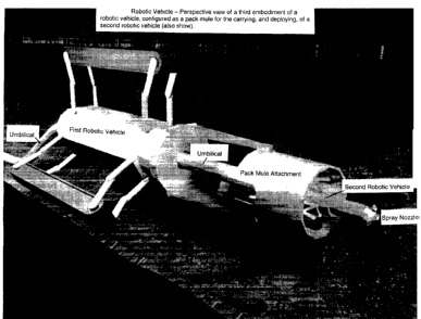
17 Fig. RV-3: Robotic Vehicle - Perspective view of a third
18 embodiment of a robotic vehicle; configured as a pack mule for the
carrying, and
19 deploying, of a second robotic vehicle (also show).
21 Fig. RV-3b: Robotic Vehicle - Perspective view of the third
22 embodiment of a robotic vehicle; configured as a pack mule for the
carrying, and
G:\SWG\Clients\Patents\E-K\Holland - RDT\CAN Rule 93\Rule 93 Application (as
filed).doc Page 7 of 15
CA 02354226 2001-07-27
1 deploying, of a second robotic vehicle (shown as deployed into a lateral sub-
2 conduit).
3
4 Fig. RV-4: Robotic Vehicle - Perspective view of a fourth
embodiment of a robotic vehicle; configured as a pack mule for the carrying,
and
6 deployment, of a second robotic vehicle (also shown). Specifications
include: a
7 tri-track drive 28" long by 4.5" wide, hydraulically driven articulating
track unit,
8 fitting inside conduits from 16" up to 24", with a maximum pressure of
1201bs/sq.
9 in. on the inner surface of the conduit, a minimum side bend of 16" (it will
travel
around bends inside the conduit), the travel speeds are variable and
reversible,
11 speed is up to 120 ft/min, and a unit line pull at a maximum torque of 1000
Ibs.
12 Optional attachments include up to six digital video cameras (3 forward
facing
13 and 3 rear facing), pressure sensors for track pressure and line pull,
multiple
14 wash head assemblies, drill head assemblies, grout form packer assemblies,
taping head assemblies, and lateral line grinder/cutter assemblies.
16
17 Fig. RV-5: Robotic Vehicle - Perspective view of a fifth
18 embodiment of a robotic vehicle; configured as a pack mule for the
carrying, and
19 deployment, of a second robotic vehicle (also shown), and configured with a
taping-head unit.
21
22 Fig. RV-6: Robotic Vehicle - Perspective view of a sixth
23 embodiment of a robotic vehicle; configured as a sprayer / cleaner vehicle.
G:\SWG\Clients\Patents\E-K\Holland - RDT\CAN Rule 93\Rule 93 Application (as
filed).doc Page 8 of 15
CA 02354226 2001-07-27
1
2 Fig. RV-7: Robotic Vehicle - Side, front and back views of the sixth
3 embodiment of a robotic vehicle; configured as a sprayer / cleaner vehicle.
4
Fig. RV-8: Robotic Vehicle - Perspective view of a seventh
6 embodiment of a robotic vehicle; with an attached drill head unit, and
sealant
7 injection. Drill head specifications include: 0.5" cement drill bit housing,
120 psi
8 500 rpm pneumatic rotary head, able to rotate 270°, able to drill
0.5" holes up to
9 6" deep, a 250 psi injection head assembly. In another embodiment the drill
head specifications include: 0.375" cement drill bit housing, 120 psi 500 rpm
11 pneumatic rotary head, able to rotate 270°, able to drill 0.375"
holes up to 4"
12 deep, a 250 psi injection head assembly.
13
14 Fig. RV-9: Robotic Vehicle - Perspective view of an eighth
embodiment of a robotic vehicle; configured as a fibre optic (conductor)
placing
16 and aligning vehicle. Specifications include: a tri-track drive 3" long,
.75" wide,
17 electrically driven, with a maximum pressure of 20 Ib/sq. in. on inner-
surface of
18 pipe, a variable travel speed of up to 10 ft/min, and a unit line pull at
maximum
19 torque of 250 Ibs (line pull varies depending on the number of inline units
deployed). Optional attachments include: up to two digital cameras (one
forward
21 facing, one rear facing), pressure sensors for track pressure and line
pull, wash
22 head assemblies, taping head assemblies, and lateral line packer head
23 assemblies.
G:\SWG\Clients\Patents\E-K\Holland - RDT\CAN Rule 93\Rule 93 Application (as
filed).doc Page 9 of 15
CA 02354226 2001-07-27
1
2 Fig. RV-10: Robotic Vehicles - Perspective view of a chain of
3 seven robotic vehicles (eight and ninth embodiments); configured as a fibre
optic
4 (conductor) placing, aligning and taping unit. Specifications for the taping
unit
embodiment include: ability to carry multiple rolls of tape, handling tape
rolls up
6 to 6" wide, carrying and deploying up to 2500' of tape on a single pass,
installing
7 up to 4 conductors in a single pass, and pulling up to 10001bs of conductor
in a
8 single pass. Other embodiments of the taping vehicle will have different
9 specifications. Another, smaller, embodiment (not shown) can carry 100' of
2"
tape, and can pull 1/a" diameter conductor up to 350'.
11
12 Fig. RV-11: Robotic Vehicles - Exploded view of a chain of three
13 robotic vehicles (eight and ninth embodiments); configured as a fibre optic
14 (conductor) placing, aligning and taping unit.
16 Fig. RV-12: Robotic Vehicles - Perspective view of a chain of six
17 robotic vehicles (eight and tenth embodiments) inside a conduit; configured
as a
18 fibre optic (conductor) placing, aligning and taping unit.
19
Fig. RV-13: Robotic Vehicle - Perspective view of an eleventh
21 embodiment of a robotic vehicle; configured as a fibre optic (conductor)
taping
22 vehicle.
G:\SWG\Clients\Patents\E-K\Holland - RDT\CAN Rule 93\Rule 93 Application (as
filed).doc Page 10 of 15
CA 02354226 2001-07-27
1 Generally the nitrogen (N2) purging spray nozzles are designed to
2 spray Plural Component polyurethane (Pur). The inlets of the components is
3 offset so that they mix in a static mixer tube, and not at the valves. The
nitrogen
4 purge blows this tube clean before the Pur can set. The mixing tube is
designed
so that there are no cavities and thus, during purging, the components are
forced
6 away from the inlet valves. Purging occurs automatically each time the
valves
7 are closed.
8 There are multiple head designs (including single, dual and quad
9 nozzles) applying the spray at prescribed angles (e.g. single nozzle at
45°, dual
nozzle at 22.5° and quad nozzle at 11.25°). The heads are
designed such that
11 there are no cavities in which the polyurethane components can mix and set.
12 The maximum flow rate of the components is 0.5 gallons / min for each head.
13 The working pressure of the nozzles is 3000 Ibs, and the bursting pressure
is
14 5000 Ibs. The temperature at the heads will vary, depending on the design,
and
ranges from 135° F to 160°F.
16
17 Fig. SN-1: Spray Nozzle - Perspective view of one embodiment of
18 a nitrogen (N2) purging spray head.
19
Fig. SN-2: Spray Nozzle - Perspective view of a second
21 embodiment of a nitrogen (N2) purging spray head.
22
G:\SWG\Clients\Patents\E-K\Holland - RDT\CAN Rule 93\Rule 93 Application (as
filed).doc Page 11 of 15
CA 02354226 2001-07-27
1 Fig. SN-3: Spray Nozzle - Perspective view of a third embodiment
2 of a nitrogen (N2) purging spray head
3
4 Fig. SN-4: Spray Nozzle - Perspective view of a fourth
embodiment of a nitrogen (N2) purging spray head
6
7 Fig. TM-1: Telescoping Member - Perspective view of one
8 embodiment of a telescoping member; configured to bridge across the
transverse
9 conduit and provide continuity to the taping path.
11 Fig. TM-2: Telescoping Member - A second perspective view of
12 one embodiment of a telescoping member; configured to bridge across the
13 transverse conduit and provide continuity to the taping path.
14
Fig. U-1: Umbilical - Perspective view of one embodiment of an
16 umbilical; containing various instrumentation, electrical and
rehabilitation supply
17 lines. The umbilical is 750 ft long, and has a flow rate of 0.5
gallons/min. It has a
18 working pressure of 30001bs, and a bursting pressure of 50001bs. The
working
19 temperature ranges from 130°F to 160°F. The umbilical is
coated both inside
and outside with Teflon to decrease the drag coefficient. Number 18 wire
21 carrying 480 volt and 2.5 amps, (i.e. 1200 watts) is used in the heating
element.
22 This wire (heating element) is only present in the first 400 feet of
umbilical, as the
G:\SWG\Clients\Patents\E-K\Holland - RDT\CAN Rule 93\Rule 93 Application (as
filed).doc Page 12 of 15
CA 02354226 2001-07-27
1 last 350 ft do not need to be heated due to the flow rates. Any joints are
tapered
2 and molded creating a one piece umbilical.
3
4
Operations
6
7 An average rehabilitation job for wastewater or storm sewer lines
8 includes the following events:
9 A vacuum truck is used for cleaning the main pipelines. The work
done by this unit is only on the main line. A wash-and-vacuum unit works with
11 the Vacuum truck to wash and clean the lateral pipelines and also does a
post-
12 wash of the main lines, then it vacuums the lines dry. At this stage
diaphragm
13 plugs are placed in the lateral pipes, which keep effluent from re-entering
the
14 cleaned pipes. The wash-and-vacuum unit is connected to the vacuum truck.
This unit is equipped with a video and data monitoring system, and also
controls
16 a robotic track drive allowing access to the lateral lines for cleaning.
This unit
17 also carries the supplemental spray components in "totes". The material in
the
18 "totes" is transferred to the main spray system as necessary. High C.F.M.
fans
19 are placed to blow air through the cleaned sections of pipe which helps
control
humidity and further dries the pipe.
21
22 Insertion of the tri-track robotic vehicles. Typically there are three such
robotic
23 vehicles; The primary unit carries the majority of the monitoring and video
G:\SWG\Clients\Patents\E-K\Holland - RDT\CAN Rule 93\Rule 93 Application (as
filed).doc Page 13 of 15
CA 02354226 2001-07-27
1 equipment and can enter pipes from 8" to 20". The secondary unit (mule)
2 designed to carry the primary unit in and out of larger pipes and allows the
3 primary unit to enter the laterals. It can enter pipes from 12" to 60". And
the
4 Tertiary unit which carries hose only and acts as a hose mule. It has no
monitoring or video equipment attached.
6
7 Setting up the spray unit includes placing track units in the pipe, setting
up the
8 pumps, and correlating the computer data, and start recording of the data.
9 Measurements of the pipe and recording of data include the density of pipe,
laser
measurement of the interior diameter of the pipe, the humidity inside the
pipe.,
11 and a video record of the pipe to check for irregularities, water
intrusion, etc.
12
13 The spray unit is driven as far into the pipe as possible. Then the main
line is
14 sprayed as the spray unit is extracted from the pipe. There are four
variables that
determine thickness of the sprayed components. The speed at which the unit is
16 extracted, the fluid temperature, the nozzle pressure, and the flow rate.
The
17 spray compound is typically composed of resin and isocyanate. The resin
18 consists of urethane and urea. Depending on data collected (ie. humidity
and
19 wall dampness) a balance between the two compounds is set. Typically the
spray compound take 3 to 10 seconds to set with a total cure time of 15-30
21 minutes.
22
G:\SWG\Clients\Patents\E-K\Holland - RDT\CAN Rule 93\Rule 93 Application (as
filed).doc Page 14 of 15
CA 02354226 2001-07-27
1 In order to spray the laterals, the spray units is re-inserted after curing
of the
2 main line. The measurements, and video recording is done as on the main
lines.
3 And the laterals are spray coated as the spray unit is extracted out. Each
section
4 can be cleaned, sprayed, and back in operation within a few short hours (a
section is 2700 feet plus lateral lines). Upon completing the lateral lines,
the
6 plugs are removed.
7
8 Figures OP-1 thru OP-20 illustrate and annotate a typical operation
9 of the invention.
11
12
13
G:\SWG\Clients\Patents\E-K\Holland - RDT\CAN Rule 93\Rule 93 Application (as
filed).doc Page 15 of 15