Note: Descriptions are shown in the official language in which they were submitted.
CA 02354288 2001-07-27
Docket No.: RHAC-0138
REFRIGERANT GAUGE MANIFOLD WITH
BUILT-IN CHARGING CALCULATOR
BACKGROUND OF THE INVENTION
The present invention generally relates to air conditioning apparatus
and, in a preferred embodiment thereof, more particularly relates to a
specially designed refrigerant gauge manifold having a built-in refrigerant
charging calculator.
As is well known in the air conditioning industry, for an air conditioning
system to properly perform at its designed-for capacity the charge level of
its refrigerant circuit must be neither too high nor too low. It is
accordingly
desirable to periodically check the amount of refrigerant which the
refrigerant circuit contains. In direct expansion type refrigerant circuits
this
is typically done by taking refrigerant pressure readings at service ports on
the liquid and suction sides of the circuit, determining the ambient
temperature adjacent the service ports, and comparing these ambient
temperature and refrigerant pressure readings to data contained on a system
charge chart which is provided by the manufacturer of the air conditioning
system.
A charge chart of this type typically has outdoor ambient dry bulb
temperature lines plotted on a liquid pressure vs. suction pressure graph. To
check the system's refrigerant charge level, the service technician determines
the outdoor ambient temperature, and the liquid and suction line pressures,
and marks on the chart the point of intersection of the determined liquid
and suction pressures. If this intersection point falls below the determined
ambient dry bulb temperature line, the technician adds refrigerant to the
CA 02354288 2001-07-27
circuit, and if the intersection point falls above the determined ambient dry
bulb temperature line, the technician removes refrigerant from the circuit.
The new liquid line/suction line pressure intersection point is then checked
against the determined ambient temperature line, and the refrigerant
addition or removal step is repeated until the pressure intersection point
falls
on the ambient pressure line on the charging chart. As an alternative to this
charge chart in graph form, the manufacturer may provide this data in
tabular form.
Several well known problems, limitations and disadvantages are
typically associated with this conventional method of checking and adjusting
the refrigerant charge level of an air conditioning system. For example, not
every service technician has appropriate instruments, sensors and the like to
efficiently carry out this process. Additionally, as conventionally carried
out,
this process is an iterative one which can be a time consuming and laborious
one. Further, a given portion of the air conditioning system may have a
number of independent circuits and associated charge charts. This presents
the possibility that the technician could utilize the wrong chart, thereby
providing a refrigerant circuit with an incorrect charge level. And, of
course,
the charging charts) initially provided by the manufacturer could be lost.
As can readily be seen from the foregoing, a need exists for an
improved technique for measuring and adjusting the charge level of an air
conditioning system refrigerant circuit that eliminates or at least
substantially
reduces the above-mentioned problems, limitations and disadvantages
commonly associated with conventional techniques for performing these
tasks. It is to this need that the present invention is directed.
SUMMARY OF THE INVENTION
In carrying out principles of the present invention, in accordance with
a preferred embodimentthereof, apparatus is provided for determining and,
-2-
CA 02354288 2001-07-27
if necessary, adjusting the charge level of an air conditioning system
refrigerant circuit.
Representatively, the apparatus comprises a porting portion
interconnectable between the circuit and a refrigerant vessel, the porting
portion being operative to selectively transfer refrigerant in a variable
direction between the circuit and the refrigerant vessel which may be, for
example, a refrigerant charging canister or a refrigerant recovery drum. The
apparatus further comprises a valve portion for operating the porting
structure, and a sensing portion for sensing ambient temperature and circuit
refrigerant pressure levels and responsively generating output signals.
The apparatus also comprises a calculator portion for storing identifying
and charging data for a plurality of air conditioning systems, receiving the
output signals and system identifying data input by an operator indicative of
the circuit being tested, and responsively creating a display indicative of
whether the circuit being tested is adequately charged, undercharged or
overcharged, the display being automatically changeable in response to
variation of at least one of the output signals caused by a flow of
refrigerant
into or out of the circuit via the refrigerant transfer port.
In a preferred embodiment of the present invention, the apparatus is
a refrigerant gauge manifold with a built-in charging calculator, and may be
easily and quickly used to both determine the sufficiency of the refrigerant
charge in the circuit being tested, and to adjust the refrigerant charge, via
the manifold, if necessary.
According to various features of the invention, in a preferred
embodiment thereof, the porting portion includes a suction port
communicatable with a suction line portion of the circuit, a liquid port
communicatable with a liquid line portion of the circuit, and a refrigerant
transfer port communicatable with a refrigerant canister or a refrigerant
-3-
CA 02354288 2001-07-27
recovery drum. The valve portion representatively includes a first valve
operative to selectively permit and preclude communication between the
suction and refrigerant transfer ports, and a second valve operative to
selectively permit and preclude communication between the liquid and
refrigerant transfer ports.
The sensing portion is representatively operative to sense ambient dry
bulb temperature and the liquid and suction line refrigerant pressures in the
circuit, and illustratively includes a first pressure-to-electric transducer
operatively coupled between the suction portand the calculator portion, and
a second pressure-to-electric transducer operatively coupled between the
liquid port and the calculator portion.
BRIEF DESCRIPTION OF THE DRAWINGS
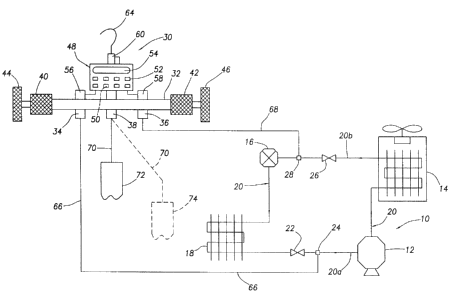
FIG. 1 is a schematic diagram of a representative air conditioning
~5 refrigerant circuit to which is operatively attached a specially designed
refrigerant gauge manifold having a built-in charging calculator and
embodying principles of the present invention; and
FIG. 2 is a schematic flow diagram illustrating the use and operation of
the refrigerant gauge manifold schematically depicted in FIG.1.
DETAILED DESCRIPTION
Schematically depicted in FIG. 1 is a representative direct expansion
type refrigerant circuit 10 used in an air conditioning system. Circuit 10 has
an outside portion including a compressor 12 and a condenser 14, and an
inside portion including an expansion valve 16 and an evaporator 18. These
-4-
CA 02354288 2001-07-27
four components of the circuit 10 are operatively connected in a
conventional manner by refrigerant-filled piping 20 including a suction or low
pressure line portion 20a extending between the outlet side of the
evaporator 18 and the inlet of the compressor 12, and a liquid or high
pressure line portion 20b extending between the outlet of the condenser 14
and the expansion valve 16.
The direction of refrigerant flow through the piping 20 during
operation of the circuit 10 is indicated by the arrows on the piping 20. A
service valve 22 and a low side pressure tap or service fitting 24 are
disposed
in the suction line portion 20a, and a service valve 26 and a high side
pressure
tap or service fitting 28 are disposed in the liquid line portion 20b.
with continuing reference to FIG.1, to check and adjust the refrigerant
charge level of the circuit 10, a specially designed refrigerant gauge
manifold
30 is provided in accordance with principles of the present invention. The
refrigerant gauge manifold 30 includes a tubular body portion 32 having
disposed on a longitudinally central portion thereof a suction port 34, a
liquid
port 36 and a refrigerant transfer port 38. Respectively mounted on the
opposite ends of the manifold body 32 are conventional manifold valves
40,42 having disc-shaped handles 44,46 that may be rotated about the axis of
the body 32 to selectively place their associated valves 40,42 in open and
closed positions.
When valve 40 is in its open position it communicates the ports 34 and
38, and when valve 40 is in its closed position it prevents communication
between the ports 34 and 38. When valve 42 is in its open position it
communicates the ports 36 and 38, and when valve 42 is in its closed position
it prevents communication between the ports 36 and 38.
According to a key aspect of the present invention, a specially designed
battery operated charging calculator 48 is mounted on the body 32 and
-s-
CA 02354288 2001-07-27
includes a microprocessor 50, a keyboard 52 useable to input data to the
microprocessor 50, and a display window 54. Stored in the microprocessor
50 are sets of charging data for a preselected set of air conditioning systems
with which the refrigerant gauge manifold 30 may be used, such data sets
containing (for each system) desired relationships among the liquid pressure,
suction pressure, and ambient dry bulb temperature for each system.
Pressure-to-electric transducers 56,58 are mounted on the body 32 and
are operative to transmit to the microprocessor 50 electric signals
respectively indicative of the refrigerant pressures at the suction and liquid
ports 34,36. An ambient dry bulb temperature sensor 60 is incorporated in
the gauge manifold 30 and is operative to transmit to the microprocessor 50
an electrical signal indicative of the ambient dry bulb temperature adjacent
the gauge manifold 30. For convenience, a hook member 64 is provided for
supporting the gauge manifold 30 on a pipe or other structure while the
gauge manifold is being used.
Flexible refrigerant hoses 66,68,70 are respectively connected to the
manifold ports 34,36,38. Hose 66 is removably connectable to the suction line
service port 24, hose 68 is removably connectable to the liquid line service
port 28, and hose 70 is selectively connectable to either a pressurized
refrigerant charging canister 72 (as indicated by the solid line position of
the
hose 70 in FIG. 1), or a refrigerant recovery drum 74 (as indicated by the
dotted line position of the hose 70 in FIG. 1). To use the refrigerant gauge
manifold 30, the manifold valves 44,46 are first closed, so that neither of
the
ports 34,36 communicates with the port 38, and the hoses 66,68 are
respectively connected to the suction and liquid line service ports 24,28 as
indicated in FIG. 1.
Referring now to FIG.1, and to FIG. 2 which illustrates in flow chart form
the use of the refrigerant gauge manifold 30, the service technician, after
-6-
CA 02354288 2001-07-27
connecting the gauge manifold 30 to the suction and liquid line portions
20a,20b as just described carries out step 76 by using the keyboard 52 to
input
system identifying data to the microprocessor 50. This identifying data
representatively includes the manufacturer, model number, system number
and electrical power frequency for the air conditioning system being tested
from a refrigerant charging level standpoint.
In addition to this system identifying data input to the calculator 48 by
the service technician, the pressure-to-electric transducers 56,58 and the
temperature sensor 60, as indicated at step 78, continuously transmit to the
microprocessor 50 input signals respectively indicative of the sensed suction
line pressure, the sensed liquid line pressure, and the sensed ambient dry
bulb temperature. In response, as indicated at step 80, the microprocessor
50 calculates (for the particular system entered by the technician) a
calculated
value P~al,liquid as a function of the sensed suction line pressure Pvaporand
sensed
ambient dry bulb temperature Ta.
Next, at step 82, the microprocessor 50 compares the sensed liquid line
refrigerant pressure P"au,a to the calculated liquid line refrigerant pressure
Pca~,~iquid and determines whether the sensed liquid line refrigerant pressure
P~Iquid is equal to, greater than or less than the calculated liquid line
refrigerant
pressure P~~,niquia~
If the microprocessor determines at step 82 that P,;4u,a is equal to
P~a~,naU~d,
the microprocessor 50, at step 84, causes the calculator 48 to create in the
display window 54 a message (such as "DONE") indicating that the circuit
charge level is correct, and the charging process is completed without the
necessity of adding refrigerant to or removing refrigerant from the circuit
10.
If the microprocessor 50 determines at step 82 that P"q~~d is less than
Pca~,~iquid~ the microprocessor 50, at step 86, causes the calculator 48 to
create
CA 02354288 2001-07-27
in the display window 54 a message (such as "ADD IN") which informs the
technician that the charge level in the circuit 10 is low. The technician then
connects the flexible hose 70 to the pressurized refrigerant charging canister
72 (see FIG. 1) and opens the manifold valve 44 to begin to flow pressurized
refrigerant into the suction line portion 20a of the circuit 10 sequentially
through the hose 70, the ports 38 and 34, the hose 66, and the service fitting
24.
During this addition of refrigerant to the circuit 10, the microprocessor
50 cycles the program through steps 78,80,82 and 86 so that the calculator 48
continues to display the "ADD IN" message which indicates to the technician
that the circuit 10 is still undercharged. When the circuit charge level is
increased to the proper level the program automatically transfers to step 84,
thereby causing the calculator 48 to display "DONE". The technician then
closes the manifold valve 44 and disconnects the refrigerant gauge manifold
from the circuit 10 and the refrigerant recharging canister 72.
If the microprocessor 50 determines at step 82 that P,~pu~a is greater than
Pca~,~ipuid~ the microprocessor 50, at step 88, causes the calculator 48 to
create
in the display window 54 a message (such as "PULL OUT°) which informs
the
technician that the charge level in the circuit 10 is too high. The technician
then connects the flexible hose 70 to the recovery drum 74 (see FIG.1) and
opens the manifold valve 46 to begin to flow pressurized refrigerant into the
recovery drum 74 sequentially via the liquid line service fitting 28, the hose
68, the ports 36 and 38, and the hose 70.
During this removal of refrigerant from the circuit 10, the
microprocessor 50 cycles the program through steps 78,80,82 and 88 so that
the calculator 48 continues to display the "PULL OUT" message which indicates
to the technician that the circuit 10 is still overcharged. When the circuit
charge level is decreased to the proper level the program automatically
_g_
CA 02354288 2001-07-27
transfers to step 84, thereby causing the calculator 48 to display
"DONE°. The
technician then closes the manifold valve 46 and disconnects the refrigerant
gauge manifold from the circuit 10 and the refrigerant recovery drum 74.
The use of the refrigerant gauge manifold 30 provides a variety of
advantages over conventional techniques for checking and adjusting the
charge level of the circuit 10. For example, the use of its valves 44,46 and
the
manner in which the gauge manifold 30 is connected to and removed from
the service fittings 24 and 28, the refrigerant canister 72 and the recovery
drum 74 are substantially identical to the valve use and connection
techniques in conventionally constructed refrigerant gauge manifolds.
Additionally, the refrigerant gauge manifold 30, when programmed with the
necessary identifying and charging data from various air conditioning systems
and units, permits a service technician to very accurately check and adjust
the
charge levels of a corresponding variety of refrigerant circuits without the
cumbersome location of their charging charts or tables, and with no related
interpolation which can dramatically slow down the refrigerant charging level
checking and adjustment task. Additionally, the usefulness of the refrigerant
gauge manifold 30 may be expanded, if desired, by simply downloading
identifying data and corresponding charging data into the microprocessor
50 from various additional air conditioning system manufacturers' websites.
In short, the refrigerant gauge manifold 30 substantially eliminates the
guesswork in the refrigerant charging process, increases the accuracy and
efficiency of the overall process, is easy and intuitive to use, and renders
the
entire field service process less costly. while the gauge manifold 30 has been
representatively illustrated herein as being utilized in conjunction with a
direct expansion type refrigerant circuit 10, it will be readily appreciated
by
those of skill in the refrigeration and air conditioning art that it could
also be
-9-
CA 02354288 2001-07-27
used to advantage in other types of refrigerant circuits, such as capillary
type
refrigerant circuits.
The foregoing detailed description is to be clearly understood as being
given by way of illustration and example only, the spirit and scope of the
present invention being limited solely by the appended claims.