Language selection

Search

Patent 2354335 Summary

Third-party information liability

Some of the information on this Web page has been provided by external sources. The Government of Canada is not responsible for the accuracy, reliability or currency of the information supplied by external sources. Users wishing to rely upon this information should consult directly with the source of the information. Content provided by external sources is not subject to official languages, privacy and accessibility requirements.

Claims and Abstract availability

Any discrepancies in the text and image of the Claims and Abstract are due to differing posting times. Text of the Claims and Abstract are posted:

  • At the time the application is open to public inspection;
  • At the time of issue of the patent (grant).
(12) Patent Application: (11) CA 2354335
(54) English Title: FUEL TEMPERATURE CONTROLLER
(54) French Title: REGULATEUR DE TEMPERATURE DE CARBURANT
Status: Deemed Abandoned and Beyond the Period of Reinstatement - Pending Response to Notice of Disregarded Communication
Bibliographic Data
(51) International Patent Classification (IPC):
  • F02M 31/16 (2006.01)
  • F02M 31/125 (2006.01)
(72) Inventors :
  • DIDUCK, VICTOR J. (Canada)
(73) Owners :
  • AIRCARE INTERNATIONAL, INC.
(71) Applicants :
  • AIRCARE INTERNATIONAL, INC. (United States of America)
(74) Agent: NEXUS LAW GROUP LLP
(74) Associate agent:
(45) Issued:
(22) Filed Date: 2001-07-30
(41) Open to Public Inspection: 2003-01-30
Examination requested: 2006-07-31
Availability of licence: N/A
Dedicated to the Public: N/A
(25) Language of filing: English

Patent Cooperation Treaty (PCT): No

(30) Application Priority Data: None

Abstracts

English Abstract


The invention disclosed provides a heat exchanger
apparatus for heating a fuel, which comprises a heat
exchanger block made of a heat conductive material. The
heat exchanger block contains a passageway in which is
located a heating element operative to heat the heat
exchanger block. A fuel conduit in contact with the surface
of the heat exchanger block conducts heat from the block to
the fuel flowing within. The heat exchanger block is shaped
in order to maximize the surface area in contact with the
fuel conduit.


Claims

Note: Claims are shown in the official language in which they were submitted.

WHAT IS CLAIMED:
1. An apparatus for heating a fuel comprising:
a) a heat exchanger block made of a heat conductive
material and having an interior passageway,
b) a heating element in said passageway operative to
heat said block,
c) a fuel conduit contacting an exterior surface of
said block operative to conduct heat from said
block to fuel flowing through said fuel conduit,
and
d) said block having a contoured shape to maximize
the contact area between said exterior surface of
said block and said fuel conduit.
2. Apparatus according to claim 1, wherein said fuel
conduit is composed of copper.
3. Apparatus according to claim 1, including a temperature
sensor operative to sense the temperature of fuel in
said fuel conduit.
4. Apparatus according to claim 3, including a controller
coupled to said sensor and said controller operative to
adjust the current flow to said heating element when
the fuel temperature rises above a predetermined upper
or falls below a lower threshold.
8

5. Apparatus according to claim 1, including a casing
enclosing said block and said fuel conduit, operative
to minimize heat loss.
6. Apparatus according to claim 5, wherein said casing is
composed of a heat insulating material.
7. Apparatus according to claim 5, wherein said heat
exchanger block is substantially longer than its width.
8. Apparatus according to claim 1, wherein said heat
exchanger block is ceramic.
9. Apparatus according to claim 6, wherein said casing is
nylon.
9

Description

Note: Descriptions are shown in the official language in which they were submitted.


CA 02354335 2001-07-30
FUEL TEMPERATURE CONTROLLER
FIELD
The present invention relates to an apparatus for
heating a fuel to a predetermined temperature with a heat
exchanger.
BACKGROUND
Hydrocarbon based fuels such as gasoline, kerosene, and
diesel fuel, are more efficient if they are heated prior to
combustion. The efficiency and engine performance is
increased while the exhaust emissions are decreased as the
temperature of the fuel is raised. In colder temperatures,
the fuel has long chain hydrocarbons and waxes, such as
laquers, which form molecules that become progressively
larger with decreasing temperature until the fuel gels.
Even if the fuel is flowing, the long chain hydrocarbons and
waxes may be large resulting in limited atomization.
Heating the fuel increases the vaporization of these
molecules.
U.S. Pat. No. 5,443,053, issued to Johnson, discloses a
fuel heater with a heat exchanger that employs an engine
heated coolant fluid or an electric immersion heater as a
source of heat. U.S. Pat. No. 5,218,944, issued to Leonard,
discloses a fuel preheating system that also employs engine
heated coolant fluid to preheat the fuel. The preheated

CA 02354335 2001-07-30
fluid is then mixed with cooled or unheated fuel to produce
the fuel 'temperature required for optimum performance.
Canadian Patent No. 960,534, issued to Zuk, discloses
winding a copper fuel line around a portion of a copper
coolant fluid line conducting coolant heated by the engine
to preheat gasoline. Canadian Patent No. 1,015,234, issued
to Lebowitz et al., discloses the use of a heat exchanger
and heated coolant fluid to raise the temperature of the
fuel.
Fuel heaters which use engine coolant as a heat source
and are comprised of a tube carrying fuel arranged around a
chamber filled with the engine coolant are known to heat
fuel to temperatures which very substantially. Accordingly,
there is a need for an improved apparatus for preheating a
fuel to an optimum temperature.
SUN~ARY
The invention disclosed provides an apparatus for
heating a fuel, which comprises a block of heat conductive
material. The heat exchanger block contains a passageway in
which is located a heating element operative to heat the
block. A fuel conduit in contact with the surface of the
heat exchanger block conducts heat from the heat exchanger
block to the fuel flowing within. The heat exchanger block
is shaped in order to maximize the surface area in contact
2

CA 02354335 2001-07-30
with the tubing or fuel conduit. The fuel conduit is made
of copper' or aluminum.
Advantageously, the apparatus includes a temperature
sensor, which senses the temperature of the fuel passing
through the fuel conduit and flowing out of the output of
the fuel conduit. The sensor may be coupled to a controller
that adjusts the current flow through the heating element
when the temperature of the fuel falls above or below a
predetermined upper or lower limit, respectively.
The apparatus may include a casing around the heat
exchanger block and fuel conduit to minimize heat loss. The
casing may contain or be formed of a heat insulating
material, such as nylon.
By using only a ceramic heat exchanger block that has a
heating coil within directly contacting the fuel conduit
over an appreciable portion of the latter, high heat
conductivity to the fuel is established with a relatively
low heat capacity attributable primarily to the ceramic heat
exchanger block. As a result, a fast response time to
temperature change requests is achieved. Unlike prior art
systems, there is no need to heat up a large amount of
material within the apparatus with the large associated heat
capacity of that material. As a result, response time in
the present invention is maximized.
3

CA 02354335 2001-07-30
BRIEF DESCRIPTION OF THE DRAWINGS
Further features and advantages will be apparent from
the following detailed description, given by way of example,
of a preferred embodiment taken in conjunction with the
accompanying drawings, wherein:
Fig. 1 is a perspective view of the heat exchanger
block;
Fig. 2 is an end view of the heat exchanger block with
adjacent fuel conduit;
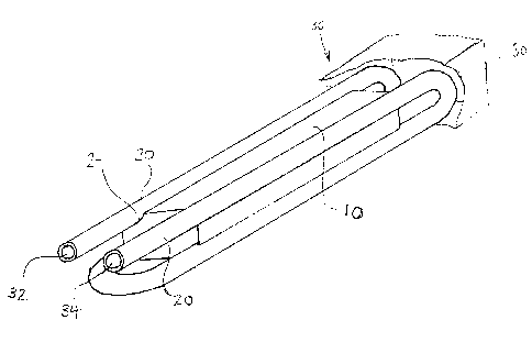
Fig. 3 is a perspective view of the encased apparatus;
Fig. 4 is a schematic view of the apparatus including a
sensor and control panel; and
Fig. 5 is a perspective view of the heat exchanger
block with adjacent fuel conduit.
DETAILED DESCRIPTION OF THE INVENTION
Referring to Fig. 1, the heat exchanger apparatus 36 is
comprised of a heat exchanger block 10, with interior
passageways 12 containing a heating element 14. A fuel
conduit 20 made of copper passes around the heat exchanger
block 10 in contact with the exterior surface of the block
10. The elongated edges of the heat exchanger block 10 are
4

CA 02354335 2001-07-30
of a rounded concave shape to maximize surface contact with
the fuel 'conduit for efficient heat transfer. In the
embodiment shown, the end of the heat exchanger block 10 is
recessed to protect the exposed portion of the heating
element 14. Fuel flows through the fuel conduit 20 and is
heated by the direct contact between the fuel conduit 20 and
the heat exchanger block 10.
Referring to Fig. 2, the fuel conduit 20 surrounds the
heat exchanger block 10. A casing 30 encloses the heat
exchanger block 10 and fuel conduit 20, with input 32 and
output 34 apertures for the fuel conduit and for connection
of the heating element 14 to a power source. The input 32
and output 34 for the fuel conduit 20 extend beyond the
front edge of the heat exchanger block 10 and pass through
the casing 30 for connection with the main fuel line (not
shown).
The encased heat exchanger apparatus 36 in Fig. 3 has
the input 32 and output 34 for the fuel conduit 20 and the
leads 16 for connection of the heating element 14 to a power
supply 22 (see Fig. 4) as the only visible components.
The apparatus in Fig. 4 includes a temperature sensor
26 and a controller 28. The sensor 26 measures the
temperature of the fuel at the output 34 of the fuel conduit
5

CA 02354335 2001-07-30
20 and relays that information to the controller 28. The
controller 28 then adjusts the current flow to the heating
element 14 in response to the measured temperature as
compared to a predetermined upper and lower limit. In this
embodiment, the controller 28 is connected in series with
the heating element 14 to a power source 22.
Referring to Fig. 5, the fuel conduit 20 contacts the
heat exchanger block 10 along each one of four partially
elongated cylindrical surfaces 24. With each fuel conduit
interconnected to an adjacent fuel conduit 20 with
integral curved tubular sections so that fuel entering the
input 32 passes down four straight elongated sections where
heat is extracted by the heat exchanger block 10 with the
15 heated fuel exiting from output 34. An insulating casing 30
(see Fig. 3) fits over the entire assembly.
By using a heat exchanger block 10 in contact with an
appreciable portion of the fuel conduit 20, good heat
20 transfer from the heat exchanger block 10 to the fuel is
achieved with relatively small heat capacity due only to the
mass of the heat exchanger block 10. As a result a fast
response time to temperature adjustment is achieved.
It can be shown that the rate of temperature change,
RT, is proportional to Lz/D where L is the length of the heat
6

CA 02354335 2001-07-30
exchanger and D is the diameter of the fuel conduit 20.
Accordingly, maximizing the length of the heat exchanger
block 10 to provide a long, narrow profile maximizes the
rate of temperature change of fluid flowing in the fuel
conduit.
Accordingly, while this invention has been described
with reference to illustrative embodiments, this description
is not intended to be construed in a limiting sense.
Various modifications of the illustrative embodiments, as
well as other embodiments of the invention, will be apparent
to persons skilled in the art upon reference to this
description. It is therefore contemplated that the appended
claims will cover any such modifications or embodiments as
fall within the true scope of the invention.
7

Representative Drawing
A single figure which represents the drawing illustrating the invention.
Administrative Status

2024-08-01:As part of the Next Generation Patents (NGP) transition, the Canadian Patents Database (CPD) now contains a more detailed Event History, which replicates the Event Log of our new back-office solution.

Please note that "Inactive:" events refers to events no longer in use in our new back-office solution.

For a clearer understanding of the status of the application/patent presented on this page, the site Disclaimer , as well as the definitions for Patent , Event History , Maintenance Fee  and Payment History  should be consulted.

Event History

Description Date
Inactive: Agents merged 2011-07-07
Letter Sent 2006-09-15
Application Not Reinstated by Deadline 2006-07-31
Time Limit for Reversal Expired 2006-07-31
All Requirements for Examination Determined Compliant 2006-07-31
Request for Examination Received 2006-07-31
Request for Examination Requirements Determined Compliant 2006-07-31
Inactive: IPC from MCD 2006-03-12
Deemed Abandoned - Failure to Respond to Maintenance Fee Notice 2005-08-01
Application Published (Open to Public Inspection) 2003-01-30
Inactive: Cover page published 2003-01-29
Inactive: Correspondence - Formalities 2002-07-15
Inactive: First IPC assigned 2001-09-19
Inactive: Filing certificate - No RFE (English) 2001-08-23
Filing Requirements Determined Compliant 2001-08-23
Letter Sent 2001-08-23
Application Received - Regular National 2001-08-23

Abandonment History

Abandonment Date Reason Reinstatement Date
2005-08-01

Maintenance Fee

The last payment was received on 2006-07-31

Note : If the full payment has not been received on or before the date indicated, a further fee may be required which may be one of the following

  • the reinstatement fee;
  • the late payment fee; or
  • additional fee to reverse deemed expiry.

Please refer to the CIPO Patent Fees web page to see all current fee amounts.

Fee History

Fee Type Anniversary Year Due Date Paid Date
Application fee - small 2001-07-30
Registration of a document 2001-07-30
MF (application, 2nd anniv.) - small 02 2003-07-30 2003-07-30
MF (application, 3rd anniv.) - small 03 2004-07-30 2004-07-30
Request for examination - small 2006-07-31
MF (application, 5th anniv.) - small 05 2006-07-31 2006-07-31
Owners on Record

Note: Records showing the ownership history in alphabetical order.

Current Owners on Record
AIRCARE INTERNATIONAL, INC.
Past Owners on Record
VICTOR J. DIDUCK
Past Owners that do not appear in the "Owners on Record" listing will appear in other documentation within the application.
Documents

To view selected files, please enter reCAPTCHA code :


To view images, click a link in the Document Description column. To download the documents, select one or more checkboxes in the first column and then click the "Download Selected in PDF format (Zip Archive)" or the "Download Selected as Single PDF" button.

List of published and non-published patent-specific documents on the CPD .

If you have any difficulty accessing content, you can call the Client Service Centre at 1-866-997-1936 or send them an e-mail at CIPO Client Service Centre.


Document
Description 
Date
(yyyy-mm-dd) 
Number of pages   Size of Image (KB) 
Representative drawing 2003-01-02 1 11
Cover Page 2003-01-02 1 35
Drawings 2002-07-15 3 32
Description 2001-07-30 7 259
Abstract 2001-07-30 1 20
Drawings 2001-07-30 3 61
Claims 2001-07-30 2 51
Courtesy - Certificate of registration (related document(s)) 2001-08-23 1 136
Filing Certificate (English) 2001-08-23 1 175
Request for evidence or missing transfer 2002-07-31 1 109
Reminder of maintenance fee due 2003-04-01 1 107
Courtesy - Abandonment Letter (Maintenance Fee) 2005-08-24 1 173
Reminder - Request for Examination 2006-04-03 1 125
Acknowledgement of Request for Examination 2006-09-15 1 176
Correspondence 2001-08-23 1 18
Correspondence 2002-07-15 4 61
Fees 2003-07-30 1 37
Fees 2004-07-30 1 30
Fees 2005-08-02 1 32
Fees 2006-07-31 1 31