Sélection de la langue

Search

Sommaire du brevet 2354335 

Énoncé de désistement de responsabilité concernant l'information provenant de tiers

Une partie des informations de ce site Web a été fournie par des sources externes. Le gouvernement du Canada n'assume aucune responsabilité concernant la précision, l'actualité ou la fiabilité des informations fournies par les sources externes. Les utilisateurs qui désirent employer cette information devraient consulter directement la source des informations. Le contenu fourni par les sources externes n'est pas assujetti aux exigences sur les langues officielles, la protection des renseignements personnels et l'accessibilité.

Disponibilité de l'Abrégé et des Revendications

L'apparition de différences dans le texte et l'image des Revendications et de l'Abrégé dépend du moment auquel le document est publié. Les textes des Revendications et de l'Abrégé sont affichés :

  • lorsque la demande peut être examinée par le public;
  • lorsque le brevet est émis (délivrance).
(12) Demande de brevet: (11) CA 2354335
(54) Titre français: REGULATEUR DE TEMPERATURE DE CARBURANT
(54) Titre anglais: FUEL TEMPERATURE CONTROLLER
Statut: Réputée abandonnée et au-delà du délai pour le rétablissement - en attente de la réponse à l’avis de communication rejetée
Données bibliographiques
Abrégés

Abrégé anglais


The invention disclosed provides a heat exchanger
apparatus for heating a fuel, which comprises a heat
exchanger block made of a heat conductive material. The
heat exchanger block contains a passageway in which is
located a heating element operative to heat the heat
exchanger block. A fuel conduit in contact with the surface
of the heat exchanger block conducts heat from the block to
the fuel flowing within. The heat exchanger block is shaped
in order to maximize the surface area in contact with the
fuel conduit.

Revendications

Note : Les revendications sont présentées dans la langue officielle dans laquelle elles ont été soumises.


WHAT IS CLAIMED:
1. An apparatus for heating a fuel comprising:
a) a heat exchanger block made of a heat conductive
material and having an interior passageway,
b) a heating element in said passageway operative to
heat said block,
c) a fuel conduit contacting an exterior surface of
said block operative to conduct heat from said
block to fuel flowing through said fuel conduit,
and
d) said block having a contoured shape to maximize
the contact area between said exterior surface of
said block and said fuel conduit.
2. Apparatus according to claim 1, wherein said fuel
conduit is composed of copper.
3. Apparatus according to claim 1, including a temperature
sensor operative to sense the temperature of fuel in
said fuel conduit.
4. Apparatus according to claim 3, including a controller
coupled to said sensor and said controller operative to
adjust the current flow to said heating element when
the fuel temperature rises above a predetermined upper
or falls below a lower threshold.
8

5. Apparatus according to claim 1, including a casing
enclosing said block and said fuel conduit, operative
to minimize heat loss.
6. Apparatus according to claim 5, wherein said casing is
composed of a heat insulating material.
7. Apparatus according to claim 5, wherein said heat
exchanger block is substantially longer than its width.
8. Apparatus according to claim 1, wherein said heat
exchanger block is ceramic.
9. Apparatus according to claim 6, wherein said casing is
nylon.
9

Description

Note : Les descriptions sont présentées dans la langue officielle dans laquelle elles ont été soumises.

CA 02354335 2001-07-30
FUEL TEMPERATURE CONTROLLER
FIELD
The present invention relates to an apparatus for
heating a fuel to a predetermined temperature with a heat
exchanger.
BACKGROUND
Hydrocarbon based fuels such as gasoline, kerosene, and
diesel fuel, are more efficient if they are heated prior to
combustion. The efficiency and engine performance is
increased while the exhaust emissions are decreased as the
temperature of the fuel is raised. In colder temperatures,
the fuel has long chain hydrocarbons and waxes, such as
laquers, which form molecules that become progressively
larger with decreasing temperature until the fuel gels.
Even if the fuel is flowing, the long chain hydrocarbons and
waxes may be large resulting in limited atomization.
Heating the fuel increases the vaporization of these
molecules.
U.S. Pat. No. 5,443,053, issued to Johnson, discloses a
fuel heater with a heat exchanger that employs an engine
heated coolant fluid or an electric immersion heater as a
source of heat. U.S. Pat. No. 5,218,944, issued to Leonard,
discloses a fuel preheating system that also employs engine
heated coolant fluid to preheat the fuel. The preheated

CA 02354335 2001-07-30
fluid is then mixed with cooled or unheated fuel to produce
the fuel 'temperature required for optimum performance.
Canadian Patent No. 960,534, issued to Zuk, discloses
winding a copper fuel line around a portion of a copper
coolant fluid line conducting coolant heated by the engine
to preheat gasoline. Canadian Patent No. 1,015,234, issued
to Lebowitz et al., discloses the use of a heat exchanger
and heated coolant fluid to raise the temperature of the
fuel.
Fuel heaters which use engine coolant as a heat source
and are comprised of a tube carrying fuel arranged around a
chamber filled with the engine coolant are known to heat
fuel to temperatures which very substantially. Accordingly,
there is a need for an improved apparatus for preheating a
fuel to an optimum temperature.
SUN~ARY
The invention disclosed provides an apparatus for
heating a fuel, which comprises a block of heat conductive
material. The heat exchanger block contains a passageway in
which is located a heating element operative to heat the
block. A fuel conduit in contact with the surface of the
heat exchanger block conducts heat from the heat exchanger
block to the fuel flowing within. The heat exchanger block
is shaped in order to maximize the surface area in contact
2

CA 02354335 2001-07-30
with the tubing or fuel conduit. The fuel conduit is made
of copper' or aluminum.
Advantageously, the apparatus includes a temperature
sensor, which senses the temperature of the fuel passing
through the fuel conduit and flowing out of the output of
the fuel conduit. The sensor may be coupled to a controller
that adjusts the current flow through the heating element
when the temperature of the fuel falls above or below a
predetermined upper or lower limit, respectively.
The apparatus may include a casing around the heat
exchanger block and fuel conduit to minimize heat loss. The
casing may contain or be formed of a heat insulating
material, such as nylon.
By using only a ceramic heat exchanger block that has a
heating coil within directly contacting the fuel conduit
over an appreciable portion of the latter, high heat
conductivity to the fuel is established with a relatively
low heat capacity attributable primarily to the ceramic heat
exchanger block. As a result, a fast response time to
temperature change requests is achieved. Unlike prior art
systems, there is no need to heat up a large amount of
material within the apparatus with the large associated heat
capacity of that material. As a result, response time in
the present invention is maximized.
3

CA 02354335 2001-07-30
BRIEF DESCRIPTION OF THE DRAWINGS
Further features and advantages will be apparent from
the following detailed description, given by way of example,
of a preferred embodiment taken in conjunction with the
accompanying drawings, wherein:
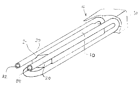
Fig. 1 is a perspective view of the heat exchanger
block;
Fig. 2 is an end view of the heat exchanger block with
adjacent fuel conduit;
Fig. 3 is a perspective view of the encased apparatus;
Fig. 4 is a schematic view of the apparatus including a
sensor and control panel; and
Fig. 5 is a perspective view of the heat exchanger
block with adjacent fuel conduit.
DETAILED DESCRIPTION OF THE INVENTION
Referring to Fig. 1, the heat exchanger apparatus 36 is
comprised of a heat exchanger block 10, with interior
passageways 12 containing a heating element 14. A fuel
conduit 20 made of copper passes around the heat exchanger
block 10 in contact with the exterior surface of the block
10. The elongated edges of the heat exchanger block 10 are
4

CA 02354335 2001-07-30
of a rounded concave shape to maximize surface contact with
the fuel 'conduit for efficient heat transfer. In the
embodiment shown, the end of the heat exchanger block 10 is
recessed to protect the exposed portion of the heating
element 14. Fuel flows through the fuel conduit 20 and is
heated by the direct contact between the fuel conduit 20 and
the heat exchanger block 10.
Referring to Fig. 2, the fuel conduit 20 surrounds the
heat exchanger block 10. A casing 30 encloses the heat
exchanger block 10 and fuel conduit 20, with input 32 and
output 34 apertures for the fuel conduit and for connection
of the heating element 14 to a power source. The input 32
and output 34 for the fuel conduit 20 extend beyond the
front edge of the heat exchanger block 10 and pass through
the casing 30 for connection with the main fuel line (not
shown).
The encased heat exchanger apparatus 36 in Fig. 3 has
the input 32 and output 34 for the fuel conduit 20 and the
leads 16 for connection of the heating element 14 to a power
supply 22 (see Fig. 4) as the only visible components.
The apparatus in Fig. 4 includes a temperature sensor
26 and a controller 28. The sensor 26 measures the
temperature of the fuel at the output 34 of the fuel conduit
5

CA 02354335 2001-07-30
20 and relays that information to the controller 28. The
controller 28 then adjusts the current flow to the heating
element 14 in response to the measured temperature as
compared to a predetermined upper and lower limit. In this
embodiment, the controller 28 is connected in series with
the heating element 14 to a power source 22.
Referring to Fig. 5, the fuel conduit 20 contacts the
heat exchanger block 10 along each one of four partially
elongated cylindrical surfaces 24. With each fuel conduit
interconnected to an adjacent fuel conduit 20 with
integral curved tubular sections so that fuel entering the
input 32 passes down four straight elongated sections where
heat is extracted by the heat exchanger block 10 with the
15 heated fuel exiting from output 34. An insulating casing 30
(see Fig. 3) fits over the entire assembly.
By using a heat exchanger block 10 in contact with an
appreciable portion of the fuel conduit 20, good heat
20 transfer from the heat exchanger block 10 to the fuel is
achieved with relatively small heat capacity due only to the
mass of the heat exchanger block 10. As a result a fast
response time to temperature adjustment is achieved.
It can be shown that the rate of temperature change,
RT, is proportional to Lz/D where L is the length of the heat
6

CA 02354335 2001-07-30
exchanger and D is the diameter of the fuel conduit 20.
Accordingly, maximizing the length of the heat exchanger
block 10 to provide a long, narrow profile maximizes the
rate of temperature change of fluid flowing in the fuel
conduit.
Accordingly, while this invention has been described
with reference to illustrative embodiments, this description
is not intended to be construed in a limiting sense.
Various modifications of the illustrative embodiments, as
well as other embodiments of the invention, will be apparent
to persons skilled in the art upon reference to this
description. It is therefore contemplated that the appended
claims will cover any such modifications or embodiments as
fall within the true scope of the invention.
7

Dessin représentatif
Une figure unique qui représente un dessin illustrant l'invention.
États administratifs

2024-08-01 : Dans le cadre de la transition vers les Brevets de nouvelle génération (BNG), la base de données sur les brevets canadiens (BDBC) contient désormais un Historique d'événement plus détaillé, qui reproduit le Journal des événements de notre nouvelle solution interne.

Veuillez noter que les événements débutant par « Inactive : » se réfèrent à des événements qui ne sont plus utilisés dans notre nouvelle solution interne.

Pour une meilleure compréhension de l'état de la demande ou brevet qui figure sur cette page, la rubrique Mise en garde , et les descriptions de Brevet , Historique d'événement , Taxes périodiques et Historique des paiements devraient être consultées.

Historique d'événement

Description Date
Inactive : Regroupement d'agents 2011-07-07
Lettre envoyée 2006-09-15
Demande non rétablie avant l'échéance 2006-07-31
Le délai pour l'annulation est expiré 2006-07-31
Toutes les exigences pour l'examen - jugée conforme 2006-07-31
Requête d'examen reçue 2006-07-31
Exigences pour une requête d'examen - jugée conforme 2006-07-31
Inactive : CIB de MCD 2006-03-12
Réputée abandonnée - omission de répondre à un avis sur les taxes pour le maintien en état 2005-08-01
Demande publiée (accessible au public) 2003-01-30
Inactive : Page couverture publiée 2003-01-29
Inactive : Correspondance - Formalités 2002-07-15
Inactive : CIB en 1re position 2001-09-19
Inactive : Certificat de dépôt - Sans RE (Anglais) 2001-08-23
Exigences de dépôt - jugé conforme 2001-08-23
Lettre envoyée 2001-08-23
Demande reçue - nationale ordinaire 2001-08-23

Historique d'abandonnement

Date d'abandonnement Raison Date de rétablissement
2005-08-01

Taxes périodiques

Le dernier paiement a été reçu le 2006-07-31

Avis : Si le paiement en totalité n'a pas été reçu au plus tard à la date indiquée, une taxe supplémentaire peut être imposée, soit une des taxes suivantes :

  • taxe de rétablissement ;
  • taxe pour paiement en souffrance ; ou
  • taxe additionnelle pour le renversement d'une péremption réputée.

Veuillez vous référer à la page web des taxes sur les brevets de l'OPIC pour voir tous les montants actuels des taxes.

Historique des taxes

Type de taxes Anniversaire Échéance Date payée
Taxe pour le dépôt - petite 2001-07-30
Enregistrement d'un document 2001-07-30
TM (demande, 2e anniv.) - petite 02 2003-07-30 2003-07-30
TM (demande, 3e anniv.) - petite 03 2004-07-30 2004-07-30
Requête d'examen - petite 2006-07-31
TM (demande, 5e anniv.) - petite 05 2006-07-31 2006-07-31
Titulaires au dossier

Les titulaires actuels et antérieures au dossier sont affichés en ordre alphabétique.

Titulaires actuels au dossier
AIRCARE INTERNATIONAL, INC.
Titulaires antérieures au dossier
VICTOR J. DIDUCK
Les propriétaires antérieurs qui ne figurent pas dans la liste des « Propriétaires au dossier » apparaîtront dans d'autres documents au dossier.
Documents

Pour visionner les fichiers sélectionnés, entrer le code reCAPTCHA :


Pour visualiser une image, cliquer sur un lien dans la colonne description du document. Pour télécharger l'image (les images), cliquer l'une ou plusieurs cases à cocher dans la première colonne et ensuite cliquer sur le bouton "Télécharger sélection en format PDF (archive Zip)" ou le bouton "Télécharger sélection (en un fichier PDF fusionné)".

Liste des documents de brevet publiés et non publiés sur la BDBC .

Si vous avez des difficultés à accéder au contenu, veuillez communiquer avec le Centre de services à la clientèle au 1-866-997-1936, ou envoyer un courriel au Centre de service à la clientèle de l'OPIC.


Description du
Document 
Date
(aaaa-mm-jj) 
Nombre de pages   Taille de l'image (Ko) 
Dessin représentatif 2003-01-02 1 11
Page couverture 2003-01-02 1 35
Dessins 2002-07-15 3 32
Description 2001-07-30 7 259
Abrégé 2001-07-30 1 20
Dessins 2001-07-30 3 61
Revendications 2001-07-30 2 51
Courtoisie - Certificat d'enregistrement (document(s) connexe(s)) 2001-08-23 1 136
Certificat de dépôt (anglais) 2001-08-23 1 175
Demande de preuve ou de transfert manquant 2002-07-31 1 109
Rappel de taxe de maintien due 2003-04-01 1 107
Courtoisie - Lettre d'abandon (taxe de maintien en état) 2005-08-24 1 173
Rappel - requête d'examen 2006-04-03 1 125
Accusé de réception de la requête d'examen 2006-09-15 1 176
Correspondance 2001-08-23 1 18
Correspondance 2002-07-15 4 61
Taxes 2003-07-30 1 37
Taxes 2004-07-30 1 30
Taxes 2005-08-02 1 32
Taxes 2006-07-31 1 31