Language selection

Search

Patent 2354412 Summary

Third-party information liability

Some of the information on this Web page has been provided by external sources. The Government of Canada is not responsible for the accuracy, reliability or currency of the information supplied by external sources. Users wishing to rely upon this information should consult directly with the source of the information. Content provided by external sources is not subject to official languages, privacy and accessibility requirements.

Claims and Abstract availability

Any discrepancies in the text and image of the Claims and Abstract are due to differing posting times. Text of the Claims and Abstract are posted:

  • At the time the application is open to public inspection;
  • At the time of issue of the patent (grant).
(12) Patent Application: (11) CA 2354412
(54) English Title: DOOR ARRANGEMENT FOR TENSIONED MEMBRANE STRUCTURE
(54) French Title: PORTE POUR STRUCTURE A MEMBRANE TENDUE
Status: Deemed Abandoned and Beyond the Period of Reinstatement - Pending Response to Notice of Disregarded Communication
Bibliographic Data
(51) International Patent Classification (IPC):
  • E06B 5/00 (2006.01)
  • E04B 1/32 (2006.01)
  • E04B 1/342 (2006.01)
  • E04H 6/44 (2006.01)
  • E06B 3/01 (2006.01)
(72) Inventors :
  • SPRUNG, PHILIP D. (Canada)
(73) Owners :
  • SPRUNG INSTANT STRUCTURES LTD.
(71) Applicants :
  • SPRUNG INSTANT STRUCTURES LTD. (Canada)
(74) Agent: SMART & BIGGAR LP
(74) Associate agent:
(45) Issued:
(22) Filed Date: 2001-07-30
(41) Open to Public Inspection: 2003-01-30
Availability of licence: N/A
Dedicated to the Public: N/A
(25) Language of filing: English

Patent Cooperation Treaty (PCT): No

(30) Application Priority Data: None

Abstracts

English Abstract


There is provided an opening structure for a tensioned membrane structure,
which structure includes a an arcuate, angular or other non-flat end, said
opening
structures comprising: an end part comprising at least a part of the end; a
pivot
associated with the end part for pivotal movement of the ends relative to the
structure part; a transport framework within the end part for maintaining the
integrity
of the tensioned membrane structure of the end part; and rollers operatively
connected at the bottom of the framework for rolling movement of the end part.


Claims

Note: Claims are shown in the official language in which they were submitted.

-5-
THE EMBODIMENTS OF THE INVENTION IN WHICH AN EXCLUSIVE PROPERTY
OR PRIVILEGE IS CLAIMED ARE DEFINED AS FOLLOWS:
1. An opening structure for a tensioned membrane structure, which structure
includes an arcuate, angular or other non-flat end, said opening structures
comprising:
an end part comprising at least a part of said end;
a pivot associated with said end part for pivotal movement of said ends
relative to said structure part;
a transport framework within said end part for maintaining the integrity of
the tensioned membrane structure of said end part; and
rollers operatively connected at the bottom of said framework for rolling
movement of said end part.
2. The structure of claim 1 comprising two said end parts which together
comprise
said end of said tensioned membrane structure.
3. The structure of claim 2 wherein said two end parts each comprise half of
said
end.
4. The structure of claim 2 wherein each said end part includes a framework
for
maintaining the integrity of each said part for all positions of said part.
5. The structure of claim 4 wherein each said end part is a self-supporting
structure.

Description

Note: Descriptions are shown in the official language in which they were submitted.


CA 02354412 2001-07-30
-1-
FIELD OF THE INVENTION
This application relates to stressed membrane structures and to opening or
door
arrangements for such structures.
BACKGROUND OF THE INVENTION
Tensioned membrane structures have been in use for many years, and
in many situations offer advantages over conventional structures. One area
where such
structures are very attractive is for use as aircraft hangars.
In order to function effectively as aircraft hangars, it is necessary that
wide
opening doors be provided for ingress and egress of aircraft.
There has been an ongoing need for doors which will meet this objective
within the structural limitations of tension membrane structures. It is
preferable that
such doors retain the relocatabilitywhich has been the hallmark of tensioned
membrane
structures, while meeting structural criteria such as wind resistance.
The present invention arises against this background.
PRIOR ART
Applicant's prior U.S. Patent 5,283,993 illustrates a door arrangement for
tensioned membrane structures.

CA 02354412 2001-07-30
-2--
BRIEF SUMMARY OF THE INVENTION
The present invention provides an opening or a door arrangement
whereby an end of a tensioned membrane structure can be partly or fully opened
while
maintaining a tensioned condition of the end part.
BRIEF DESCRIPTION OF THE DRAWINGS
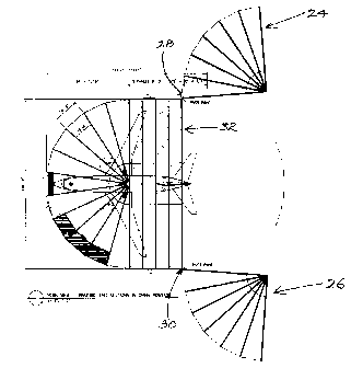
In drawings which illustrate embodiments of the invention, Figure 1 is a
top plan view of a tensioned membrane structure, showing in ghost lines an
aircraft
within the structure; Figure 2 is a plan view showing a plan view of the
structure of claim
1 with doors in an open position; Figure 3 is a plan view of a door structure
illustrating
a partially opened situation; Figure 4 is a cross-section through a framework
of the door
structure illustrated in Figure 2; and Figure 5 is a perspective view
illustrating a frame
structure for door structure of the invention.
DETAILED DESCRIPTION OF THE PREFERRED EMBODIMENTS
Tensioned membrane structure 10 comprises a framework including
structural members 12 which support tensioned membrane 14.
Various bracing arrangements, such as cable bracing 16, may be utilized
where required in structure 10.

CA 02354412 2001-07-30
-3--
Structure 10 may be provided with doors such as personnel doors 18 and
sliding door 20. Various other features, such as skylight 22, may be included.
First and second end parts 24 and 26 respectively are preferably both
provided with respective pivot connections 28 and 30 by which parts 24 and 26
are
joined to main part 32 of structure 10.
Structure 10 will generally have a substantially semi-circular end 34, and
it is desirable that at least a part of end 34 can be opened to allow access
to the
structure for large objects. In the preferred case both end parts 24 and 26
are
rotatable, so that the entire end 34 of structure 10 can be opened to the full
width of the
structure 10.
In guiding the opening and closing of end parts 24 and 26, pivot
connections 28 and 30 are preferably positioning and guiding pivots only and
are not
intended to support any part of the weight of the associated end part.
Figure 3 illustrates the positioning of the frame structure that would
normally be a part of an end 34 of a structure 10, comprising the main
structural
members 36.
The door arrangement of the present invention preferably provides a
support structure 38 associated with each structural member 36. As illustrated
in Figure
4, the support structure 38 comprises horizontal beam 40, vertical beam 42 and
diagonal beams 44 and 46.
Each support structure 38 is preferably provided with rollers which are
preferably wheels and preferably at least two wheels 48 and 50.

CA 02354412 2001-07-30
-4--
It is the combination of the support structures 38 and wheels 48 and 50
which support the weight of end parts 24 and 26 in opening and closing the end
parts.
Figure 5 illustrates an essentially complete frame for each of end parts 24
and 26. This consists of the normal structural members 36 of structure 10 and,
as well,
usual structural members 52, extending between structural members 36.
In addition, Figure 5 illustrates transverse bracing arrangements 54
between vertical beams 42 and shown consisting of horizontal members 56 and
diagonal structure 58.
End parts 24 and 26 are thus each self supporting structures.
It is noted that bracing structure is required to provide rigidity and tension
to the end parts 24 and 26, and variations on the support structure are
therefore
permissible so long as those criteria are maintained.
Connecting and/or sealing means (not shown) are preferably provided
between end parts 24 and 26 in the closed position and between end parts 24
and 26
and main part 32 of structure 10 when the end parts are in the closed
position.
As well, a drive arrangement (not shown) may be provided for opening
and closing parts 24 and 26.
Parts 24 and 26 are preferably additionally stabilized in the open and
closed positions by the use of conventional aircraft tie-down systems.

Representative Drawing
A single figure which represents the drawing illustrating the invention.
Administrative Status

2024-08-01:As part of the Next Generation Patents (NGP) transition, the Canadian Patents Database (CPD) now contains a more detailed Event History, which replicates the Event Log of our new back-office solution.

Please note that "Inactive:" events refers to events no longer in use in our new back-office solution.

For a clearer understanding of the status of the application/patent presented on this page, the site Disclaimer , as well as the definitions for Patent , Event History , Maintenance Fee  and Payment History  should be consulted.

Event History

Description Date
Time Limit for Reversal Expired 2007-07-30
Application Not Reinstated by Deadline 2007-07-30
Inactive: Abandon-RFE+Late fee unpaid-Correspondence sent 2006-07-31
Deemed Abandoned - Failure to Respond to Maintenance Fee Notice 2006-07-31
Inactive: IPC from MCD 2006-03-12
Letter Sent 2004-11-16
Reinstatement Requirements Deemed Compliant for All Abandonment Reasons 2004-10-25
Deemed Abandoned - Failure to Respond to Maintenance Fee Notice 2004-07-30
Application Published (Open to Public Inspection) 2003-01-30
Inactive: Cover page published 2003-01-29
Letter Sent 2002-12-19
Inactive: Delete abandonment 2002-12-16
Inactive: Abandoned - No reply to Office letter 2002-10-31
Inactive: Correspondence - Transfer 2002-10-28
Inactive: Transfer information requested 2002-09-05
Inactive: Single transfer 2002-06-21
Inactive: IPC assigned 2001-09-28
Inactive: First IPC assigned 2001-09-28
Inactive: Courtesy letter - Evidence 2001-08-28
Inactive: Filing certificate - No RFE (English) 2001-08-24
Filing Requirements Determined Compliant 2001-08-24
Application Received - Regular National 2001-08-24

Abandonment History

Abandonment Date Reason Reinstatement Date
2006-07-31
2004-07-30

Maintenance Fee

The last payment was received on 2005-04-07

Note : If the full payment has not been received on or before the date indicated, a further fee may be required which may be one of the following

  • the reinstatement fee;
  • the late payment fee; or
  • additional fee to reverse deemed expiry.

Please refer to the CIPO Patent Fees web page to see all current fee amounts.

Fee History

Fee Type Anniversary Year Due Date Paid Date
Application fee - standard 2001-07-30
Registration of a document 2002-10-28
MF (application, 2nd anniv.) - standard 02 2003-07-30 2003-07-09
MF (application, 3rd anniv.) - standard 03 2004-07-30 2004-10-25
Reinstatement 2004-10-25
MF (application, 4th anniv.) - standard 04 2005-08-01 2005-04-07
Owners on Record

Note: Records showing the ownership history in alphabetical order.

Current Owners on Record
SPRUNG INSTANT STRUCTURES LTD.
Past Owners on Record
PHILIP D. SPRUNG
Past Owners that do not appear in the "Owners on Record" listing will appear in other documentation within the application.
Documents

To view selected files, please enter reCAPTCHA code :


To view images, click a link in the Document Description column. To download the documents, select one or more checkboxes in the first column and then click the "Download Selected in PDF format (Zip Archive)" or the "Download Selected as Single PDF" button.

List of published and non-published patent-specific documents on the CPD .

If you have any difficulty accessing content, you can call the Client Service Centre at 1-866-997-1936 or send them an e-mail at CIPO Client Service Centre.


Document
Description 
Date
(yyyy-mm-dd) 
Number of pages   Size of Image (KB) 
Representative drawing 2003-01-02 1 13
Cover Page 2003-01-02 1 38
Abstract 2001-07-30 1 15
Description 2001-07-30 4 125
Claims 2001-07-30 1 30
Drawings 2001-07-30 5 202
Filing Certificate (English) 2001-08-24 1 175
Request for evidence or missing transfer 2002-07-31 1 109
Courtesy - Certificate of registration (related document(s)) 2002-12-19 1 106
Reminder of maintenance fee due 2003-04-01 1 107
Courtesy - Abandonment Letter (Maintenance Fee) 2004-09-27 1 178
Notice of Reinstatement 2004-11-16 1 166
Reminder - Request for Examination 2006-04-03 1 125
Courtesy - Abandonment Letter (Request for Examination) 2006-10-10 1 167
Courtesy - Abandonment Letter (Maintenance Fee) 2006-09-25 1 175
Correspondence 2001-08-24 1 24
Correspondence 2002-09-05 1 18
Fees 2003-07-09 1 31
Fees 2004-10-25 1 28
Fees 2005-04-07 1 28