Note: Descriptions are shown in the official language in which they were submitted.
CA 02354518 2001-06-12
WO 00/20332 PCTNS99I22592
1
Fauiasite Zeolitic Materials
This invention is directed to new zeolitic materials and to a method of making
them. The zeolites are prepared by high temperature treatment of a faujasitic
zeolite at
s a temperature of 600°C or higher.
Naturally occurring and synthetic zeolites have been demonstrated to exhibit
catalytic properties for various types of hydrocarbon conversions. Zeolites,
which are
ordered porous crystalline aluminosilicates, have definite crystalline
structure as
io determined by X-ray diffraction studies. Such zeolites have pores of
uniform size which
are uniquely determined by unit structure of the crystal. The zeolites are
referred to as
"molecular sieves" because interconnecting channel systems created by pores of
uniform pore size comparable to those of many organic molecular cross
sections, allow
a zeolite to selectively absorb molecules of certain dimensions and shapes.
The pores
is systems in porous zeolites may be categorized as small, medium or large
pore size,
depending on the number of oxygen atoms in the ring systems which define the
apertures to the interior pore structure of the zeolite. See Shape Selective
Catalysis in
Industrial Applications, Chen et al, Marcel Dekker, N.Y.1989, ISBN 0-8247-7856-
1.
2o The most important groups of zeolites used industrially for catalytic and
other
applications such as sorption are the medium (intermediate) and large pore
size
zeolites. Examples of the former include the widely used zeolite ZSM-5 as well
as
other materials such as ZSM-23 and ZSM-35. These zeolites are widely used in
petroleum refining processes (catalytic dewaxing, FCC additive catalyst) as
well as in
2s petrochemical processes (ethylbenzene production, xylene isomerization), to
name but
a few examples. The large pore zeolites which enjoy the greatest commercial
use are
the faujasite zeolites Y and ultrastable Y (USY); these are widely used in
petroleum
refining processes such as FCC and hydrocracking.
3o Compositionally, zeolites are metalfosilicates, with the aluminosilicates
being the
normal natural form for the zeolites which are found in nature, although other
metallosilicates such as borosilicates and ferrosilicates have also been
described. In
SUBSTITUTE SHEET (RULE 2B)
CA 02354518 2001-06-12
WO 00/20332 PCTNS99122592
2
addition, the ratio of silicon to metal in a zeolite may vary from relatively
low values to
very high ones, extending in principle to infinity, so that the ultimate
material is a
polymorph of silica. See, for example, "When is a Zeolite not a Zeolite", L.
V. C. Rees,
Nature, 296,. 491-2, 8 April 1982. For brevity, zeolites will for the most
part be
s described here as aluminosilicates although it should be remembered that
other metals
besides aluminum may replace all or part of the aluminum content of a zeolite.
In terms
of an empirical formula, zeolites may be defined by the formula:
M 2rn O xAl20s x (Si02 )y.H20
io In the empirical formula, x is equal to or greater than 2, since A104
tetrahedra are
joined only to SiO~ tetrahedra, and n is the valence of the ration designated
M. See, for
example, D. Breck, Zeolite Molecular Sieves, John Wiley & Sons, New York p.5
(1974).
In the empirical formula, the ratio of the total of silicon and aluminum atoms
to oxygen
atoms is 1:2. M was described as sodium, potassium, magnesium, calcium,
strontium
is and/or barium, which complete the electrovalence makeup of the zeoiite.
The structural framework of a zeolite is based on an i~nitely extending three-
dimensional network of A104 and Si04 tetrahedra linked to each other by
sharing all of
the oxygen atoms, so that the ratio of the total aluminum and silicon atoms to
oxygen
2o atoms is 1:2. The electrovalence of the tetrahedra containing alumina is
balanced by
the inclusion in the crystal of the ration, for example an alkali metal, an
alkaline earth
metal or an organic ration. This can be expressed in the formula above where
the ratio
of aluminum to the number of various rations, such as Cal2, Sr/2, Na, K or Li,
is equal
to unity. One type of ration may be exchanged entirely or partially with
another type of
2s ration utilizing ion exchange techniques which have now become
conventional. By
means of such ration exchange, it is possible to vary the properties of a
given
aluminosilicate by suitable selection of the ration. In the as-synthesized
materials, the
cavities and pores are occupied by molecules of water prior to dehydration
and/or
possibly by organic species from the synthesis mixture.
As previously mentioned, the silicalalumina atomic ratio of a given zeolite is
often variable. For example, zeolite X can be synthesized with silicalalumina
atomic
SUBSTITUTE SHEET (RULE 26)
CA 02354518 2001-06-12
WO 00/20332 PCT/US99/22592
3
ratios of from 1.5:1 up to 3:1, while that ratio in zeolite Y is from 3:1 to
6:1. In the
synthetic zeolite Ultrastable Y (USY), which is made from zeolite Y by a
process of
successive ammonium exchange and steaming, the silica:alumina ratio can be
made to
exceed the value of fi:1 typical for zeolite Y and extend up to high values
indeed. In
s some zeolites, the upper limit of the silicalalumina atomic ratio is
unbounded. ZSM-5 is
one such example wherein the silicalalumina ratio may extend up to infinity.
U.S. Rat.
No. 3,941,871 (RE. 29,948),discloses a porous crystalline silicate made from a
reaction
mixture containing no deliberately added aluminum and exhibiting the X-ray
diffraction
pattern characteristic of ZSM-5 zeolites.
io
The silica/alumina ratio of the "as-synthesized" zeolite can be increased by
decreasing the tetrahedral alumina content of the zeolite. Decrease in the
tetrahedral
alumina may be effected by synthetic methods developed to deplete the
tetrahedral
alumina of a zeolite. In addition, the silica:alumina ratio of a zeolite may
be increased
is (loss of tetrahedral framework alumina) as a result of process conditions
to which the
zeolite is subjected during use. Process conditions which will effect
depletion of
tetrahedral alumina include high temperature calcination and steaming.
Increased silica:alumina ratio in zeolites is associated with increased
stability to
2o hydrothermal degradation: zeolites with relatively high silica:alumina
ratios are more
resistant to the effects of steaming in that they retain crystallinity and
catalytic activity
better than zeolites of lower silica:alumina ratio. It has therefore been
considered
desirable to use zeolites of higher silica:alumina ratio in many applications
where
hydrothermal conditions are encountered either during the direct use of the
zeolite or
2s when the zeolite catalyst is undergoing regeneration. One application of
this type is in
the fluid catalytic cracking (FCC) process where the zeolitic catalyst is
exposed to high
temperatures and copious quantities of steam during the regeneration step when
the
coke which accumulates on the catalyst is oxidatively removed prior to recycle
of the
catalyst to the cracking step. Historically, the FCC process which initially
used zeolitic
3o catalysts based on zeolite X (siiica:alumina ratio up to 3:1 ), progressed
initially to the
use of catalysts based on zeolite Y (ratio of 3:1 to 6:1 ) and finally to
zeolite USY with
ratios of 6:1 or higher. The use of zeolite USY has resulted in both process
SU6STITUTE SHEET (RULE 26)
CA 02354518 2001-06-12
WO OOI20332 PCT/US99/Z2592
4
improvement in terms of catalyst stability as well as in a more desirable
slate of
products and product properties. Zeolite USY is now used in a number of other
catalytic applications requiring a large pore size zeolite, for example,
hydrocracking.
s Various treatments have been proposed for modifying the physical and
chemical
properties of zeoiites. An important method in reducing the activity of
zeolite catalysts is
by the process of steaming. By controlled steaming, it is possible to produce
zeolite
catalysts having any desired degree of activity: The degree of steaming of a
specfied
catalyst to achieve a desired activity level is largely dependent upon the
nature of the
io zeolite. Steam treatment, however, often requires long periods of time to
treat the
catalyst effectively for activity reduction.
U.S. Pat. No. 3,939,058 discloses methods of modifying the catalytic
properties
of zeolites. One such method is calcination which is defined as heating at
high
is temperatures but below the sintering temperature of the zeolite for varying
periods of
time. Other methods are also disclosed, including compositing the zeolite in a
matrix
and steam treatment. The patent further states that the crystallinity
retention of
catalysts may be improved by precaicination of the crystalline
aluminosilicate. For
example, the patent states that it has been found possible to preserve the
crystallinity of
2o aluminosilicates such as the rare earth exchanged synthetic faujasites, by
calcining the
zeolite to drive off water, thus forming a more suitable structure and
minimizing loss in
crystallinity during subsequent rapid drying, as in spray drying, wet
processing,
steaming and aging. The calcining may be accomplished by heating the
crystalline
aluminosilicate sieve after ion exchange to a temperature below the sintering
2s temperature of the sieve and generally in the range of 260 to 870°C.
Similarly, U.S. Pat. No. 4,141,859 discloses a method of controlling the
relative
acid activity of zeolite catalysts, by treating the zeolitic component with
air or steam at
elevated temperatures, e.g., up to 925°C. in air.
Calcination of the freshly synthesized zeolite to remove adsorbed water and
any
organic materials that have been used to form the zeolite crystals is
necessary to
SUBSTITUTE SHEET (RULE 26)
CA 02354518 2001-06-12
WO OOI20332 PGTNS99/Z2592
activate the zeolite and accordingly has generally been employed. Also, as
stated
above, precalcination of the zeolite has been found to stabilize the
crystallinity of the
zeolite. However, heat treatment may remove hydroxyl groups from the framework
of
the zeolite. Thus, dehydroxylation of a decationized Y zeolite is discussed in
Zeolite
s Chemistry and Catalysts, ACS Monograph 171, pages 142 and 143, in which
dehydroxylation of Y zeolite is stated to result from prolonged calcination at
relatively
high temperatures, resulting finally in the structural collapse of the zeolite
and the
formation of an amorphous silica or silica-alumina structure. For these
reasons, the use
of high temperatures has generally been avoided in zeolite synthesis. When
organic
io materials are to be removed from the freshly synthesized zeolite,
temperatures of
540°C. are. typical and generally not exceeded in order to avoid damage
to the crystal
structure.
Calcination or high temperature treatment has been employed in various
catalyst
is treatments to achieve particular results, for example, to convert
impregnated metat or
other compounds to different forms as described in U.S. Pat. Nos. 4,276,438
and
4,060,568 or to destroy ion exchange capacity as described in U.S. Pat. No.
3,0997,115. However, even in such cases the use of higher temperatures, e.g.
above
500°C., has not been preferred because of the undesirable effect on the
structure of the
2o zeolite.
Other high temperature treatment processes applied to zeolites are described
in
U.S. Patents Nos. 5,143,876; 5,102,839; 4,783,571 and 4,141,859. US. 5,227,352
describes a method for producing crystalline aluminosilicates by the thermal
shock
2s treatment of zeoiite USY; according to the description of the method it is
essential to
use USY as the starting material rather than zeolite Y itself.
Besides the specific pore configuration of a zeolite, another indicium of its
selectivity is the zeolitic surface area (ZSA) and its relationship to the
mesopore area
so (MSA). Shape selective reactions take place at the active sites in the
zeolite created by
the presence of the trivalent metal atoms in the zeolite structure; reactions
which are
not constrained by the pore structure of the zeolite - the non shape selective
reactions -
SUBSTITUTE SHEET (RULE 26)
CA 02354518 2001-06-12
WO 00/20332 PCTNS99/22592
6
may occur at catalytically active sites in the larger pores of the mesopore
regions of the
zeolite. The acidic catalytic activity of the zeolitic tetrahedral sites is
also greater than
the activity of similar but non-zeolitic sites. So, if the ZSA is relatively
large compared
to the MSA, shape selective reactions will be favored as compared to the non-
shape
s selective reactions both by reason of the relatively greater zeolitic
surface area
available for the shape selective reactions and by the relatively greater
catalytic activity
of the zeofitic sites. For this reason, a high ratio of ZSA to MSA is
preferred. So far, no
treatments specifically designed to modify the ZSA and MSA of a zeolite have
been
described.
We have now found a method to make novel large pore size crystalline zeolitic
materials. These novel crystalline materials are characterized by a high ratio
of ZSA to
MSA relative to known types of large pore size zeolite catalysts. The new
zeolitic
materials are characterized by an X-Ray Diffraction (XRD) pattern with peaks
which are
is significantly different to those of zeolite USY and which mark it out as a
novel
composition of matter.
The new zeolitic materials are made by a process of high temperature
calcination of zeolite Y. Typically, the calcination is carried out at a
temperature of at
least 600°C, normally from 600 to 1000°C, for a period of time
sufficient to bring about
the desired changes in the zeolite structure (as manifested by the change in
XRD). It
has been found that a preliminary drying step is required for optimum results
from the
high temperature calcination, this step normally being carried out at a
temperature of
100 to 350°C to remove physically bound water from the zeoiite. By
careful drying prior
2s to high temperature calcination, collapse of the zeolite crystal structure
can be avoided,
particularly at silica:alumina ratios below 5:1 in the starting material.
Another
requirement is that the Y zeolite starting material should have a sodium
content of not
more than 5 wt. percent, preferably 0.1 to 4.0 wt. percent prior to drying and
calcination.
3o The thermally treated materials have a high zeolitic surface area (ZSA)
relative
to the mesoporous surface area (MSA), indicating that catalytically, they will
exhibit a
high degree of shape selectivity, with less non-selective reactions taking
place under
SUBSTITUTE SHEET (RULE 26)
CA 02354518 2001-06-12
WO 00/20332 PCT/US99/22592
7
selected reaction conditions. Quantitatively, the present high temperature
caianed
(HTC) materials have a ZSA which is 50 to 150 m2g'' higher than that of an
ultrastable
Y zeolite of the corresponding unit cell size (UCS).
s The novel zeolite materials may be used as catalytic materials as well as
sorption materials. Catalytic applications include hydrocarbon conversion
reactions
such as catalytic cracking, hydrocracking, and other processes requiring
catalytic
mediation by a large pore size catalytic material. The relatively larger ZSA
can be
expected to improve shape selective sorption properties and the improved
thermal
io stability will be useful in processes such as catalytic cracking where the
catalyst are
exposed to hydrothermal dealuminization.
In the accompanying drawings:
is Figure 1 is a graph showing the nitrogen porosimetric analysis of a typical
high
temperature calcined zeolite Y compared with that of an ultrastable zeolite Y.
Figure 2 is a process schematic comparing the method of preparation described
below for a typical high temperature calcined zeolite Y with that of zeolite
USY, using
2o typical conditions.
The present preparation uses zeolite Y as a starting material. This zeolite,
well
established as a commercial product from a number of suppliers, has a
silica:alumina
ratio in the range of 3:1 to 6:1 measured on the basis of a bulk chemical
analysisl TGA
2s method, prior to the start of the thermal treatment. Zeolite USY which does
not
undergo the same modification of stnrcture during the high temperature
calcination is
not used as a starting material.
The unit cell size of the zeolite Y starting material will be in excess of the
UCS
so characteristic of zeolite USY, i.e. at least 2.460 nm and in many cases
will be at least
2.470 nm, for example, 2.480 or 2.490 nm. The ZSA will normally be in the
range of
850 to 950 mZg'' and MSA will be in the range of 2 to 10, usually 6 to 9
m2g''.
SUBSTITUTE SHEET (RULE 26)
CA 02354518 2001-06-12
WO 00/20332 PGT/US99/22592
8
The initial treatment step is the reduction of the sodium content to a value
below
wt. percent and which, for optimum retention of crystal structure in the
treated zeolite,
should be in the range of 0.1 to 4.0 wt. percent, normally 1 to 2.5 wt. pct.
In this step
s the zeolite Y is converted to the hydrogen or decationized form. The sodium
content of
the starting zeolite, which may vary according to the source of supply or to
the method
of synthesis used, and typically is in excess of 5 wt. pct., may be reduced by
successive conventional ration exchange steps with solutions of ammonium
rations.
For example, the zeolite Y may be exchanged with a solution of ammonium
nitrate,
io ammonium sulfate or ammonium chloride, typically at a concentration of 0.1
to 0.5 M.
Exchange may be carried out at ambient temperature or mildly elevated
temperature,
typically at atmospheric pressure.
We have found that a preliminary drying step is appropriate if the zeolite is
to
is avoid collapse and to retain sufficient crystallinity during the high
temperature
calcination. This drying step should reduce the moisture level of the zeolite
to a value
corresponding to removal of the physically bound water from the pore structure
of the
zeolite. Further drying to remove chemically bound water is not required at
this stage
with the following high temperature calcination. The drying step becomes more
2o important as the silica:alumina ratio of the starting material decreases
from 6:1 to lower
values below 5:1 since the zeolites with lower silica:alumina ratios are more
sensitive to
deaiumination under hydrothermal conditions, with consequent loss of crystal
structure.
Drying should be carried out at a temperature of from 100 to 350°C for
long enough to
reduce the total volatile content, most of which is water, to the required
level, normally
zs to less than 10 weight percent although lower levels, for example, 5 to 7
weight percent
and preferably not more than 5 weight percent, are preferred for better
retention of
crystalline characteristics and conversion to the desired zeolitic form.
Although the ZSA
remains substantially above 800 m2g ~ at moisture levels above 5 weight
percent, the
MSA increases rapidly above 5 percent water so that this value marks the
preferred
3o maximum prior to calcination. The drying step is suitably carried out in a
manner which
reduces exposure of the zeolite to the steam resulting from the drying. For
this reason,
drying is preferably carried out using either a thin layer of the zeolite or a
technique
SUBSTITUTE SHEET (RULE 26)
CA 02354518 2001-06-12
WO 00/20332 PCT/US99/22592
9
The controlled sodium, pre-dried zeolite is subjected to a calcination at a
temperature which results in a reduction in the unit cell size of the zeolite,
together
with changes in the characteristic XRD pattern and changes in the surface
areas of
s the zeolitic and mesoporous surfaces. The zeolitic surface area may increase
during
the course of the treatment in favorable cases. This calcination is normally
best
carried out at a temperature of at least 600°C, in order to produce the
desired treated
product in a reasonable period of time. Normally, the calcination temperature
will be
in the range of 600 to 1,000°C; at temperatures above 1,000°C,
dehydroxyiation of the
io zeolite may ~ proceed too fast to be readily controllable resulting in
collapse of the
crystal structure. The maximum temperature used for the calcination should be
selected to be low enough to avoid collapse of the crystal. Generally, the
starting
materials with higher silica:alumina ratios will withstand the higher
calcination
temperatures better than the ones with lower silica:alumina ratios, although
the
is technique used for the calcination will also affect the choice of
temperature, with
methods which minimize the exposure of the crystal to steam permitting
relatively
higher temperatures. There is an optimum temperature range for calcining each
starting material which results in the attainment of the highest ZSA relative
to UCS.
This temperature, which is usually between 650 and 800°C, as well as
the maximum
2o temperature for any given starting material may be selected by simple
empirical
determination. Calcination temperatures from 650 to 750°C will normally
give
acceptable results with most starting materials.
The calcination is carried out without any intentional addition of water, i.e
is
2s carried out "dry", except for the presence of water vapor released by the
dehydroxylation of the zeolite during the treatment. Again, the calcination
should be
carried out in a manner which minimizes the exposure of the zeolite to the
released
moisture, as for example, by conducting the treatment in a thin layer of the
zeolite of
using a technique such as a muffle oven which removes the water vapor rapidly
from
3o the zeolite. If desired,the calcination may be carried out under an inert
(non-reactive)
atmosphere such as nitrogen, although this has not been found to be necessary.
The
caicination is continued until the desired changes in the zeolite crystal
structure are
SUBSTITUTE SHEET (RULE 2B)
CA 02354518 2001-06-12
WO 00/20332 PCT/US99/22592
achieved, as manifested by the XRD (or other indicia as discussed below) of
the novel
material.
The novel crystalline zeolitic materials are characterized by a number of
s features which definitely mark them out as being distinguished from existing
forms of
zeolites. In particular, they are distinct from the zeolite Y starting
material in having a
lower UCS as well as by a lower proportion of pores in the mesoporous range,
taken
as the pores with a diameter of 0.4 nm or higher, relative to a similar USY of
the same
UCS. The UCS may decrease to values as low as 2.440 nm, comparable to those of
io zeolite USY although the zeolitic material can be readily distinguished
from USY by
other characterizing properties, as described below. The UCS will normally be
in the
range of 2.440 to 2.465 nm, preferably 2.450 to 2:454 nm. The UCS may
typically
decrease up to 0.015 nm as a result of the calcination without structural
collapse of
the zeolite crystal structure.
~s
The novel materials are readily distinguishable from zeolite USY in having a
higher ZSA to MSA ratio for the corresponding UCS and second, a different XRD
pattern. The zeolitic surface area of the catalyst may be determined by ASTM D
4365-85 (Standard Test Method for Determining Zeolite Area of a Catalyst). The
2o mesoporous surface area is equated to the matrix area of D 4365-85, that is
the
difference between the total surface area of the catalyst and the zeolite
surface area.
The total surface area of the catalyst may be determined by ASTM D 3663.
To take an example of this increased ratio of zeofite surface area relative to
the
2s non-zeolitic, mesoporous surface area, a sample of zeolite Y with a
silica:alumina ratio
of 5.5:1 may be converted to USY zeolite by ammonium exchange followed by
steaming at 650 to 750°C in 100°~ steam, to give a USY zeolite
product with a UCS of
24.52 to 24.54 and a ZSA of 700-750 and a MSA of 40-60. If, however, the same
exchanged starting material is dry calcined at 800°C for 1 hour (no
steam added), the
3o final UCS is lower at 24.50 and the ratio of ZSA to MSA is markedly more
favorable at
ZSA= 838, MSA=11. The zeolitic surface area of the calcined product is
normally at
least 800 m2g'' and in most cases at least 850 or more, e.g. above 880 m2g''
to 900
m2g'', with the mesoporous surface area usually being not more than 15 m2g''
and in
CA 02354518 2001-06-12
WO OOI20332 PCT/US99/22592
11
most cases not more than 10 m2g''. The ratio of zeolitic surface area to
mesoporous
surface area in the calcined products is at least 30:1 and in most cases at
least 50:1
or higher; ratios in the range 60:1 to 100:1 are readily achievable.
s The concomitant of the increased ratio of zeolitic surface area to
mesoporous
surface area is a greater mesoporous volume relative to the similar USY
zeolite. This
is demonstrated by Figure 1 which is a graph showing the nitrogen porosimetric
analysis of a typical high temperature calcined zeolite Y compared with that
of an
ultrastable zeolite Y of the same unit cell size. The figure demonstrates that
the high
io temperature calcined zeoiite (UCS=2.45 nm) possesses a relatively smaller
pore
volume in the mesoporous size range than the corresponding USY zeolite. In
particular, the high temperature calcined zeolite Y has negligible pore volume
above 5
nm.
is The XRD pattern for the novel materials has a significantly different peak
ratio
than the USY zeolite with the same UCS. The peak height ratio is calculated by
reference to the peak in the XRD pattern which is found at a 28 value below
10°,
usually at 5-6° (2A) (Peak No. 1 ). The heights of the peaks which
occur at 28 values
above 10° relative to the height of the peak below 10° are as
follows for the novel
2o zeolitic materials, with exemplary values given for the peak positions
above 10°
(expressed as 2 8 angle). In the table, as in all reported XRD values in this
specification, the XRD values are obtained with Cu K alpha radiation, 0.15406
nm).
Peak 2 8 ~ RatiopH
No.
1 8.20 0.20 -
t
2 10.2 0.20 not more than
t 0.20
3 12.0 0.30 not more than
t 0.15
4 15.7 0.30 not more than
t 0.30
18.8 0.40 not more than
t 0.10
6 20.5 0.40 not more than
t 0.15
7 23.8 0.50 not more than
t 0.20
8 27.2 0.60 not more than
t 0.12
9 31.6 0.70 not more than
t 0.10
CA 02354518 2001-06-12
WO 00/20332 PCT/US99/2Z592
12
During the treatment, the acidity of the zeolite will decrease as a result of
the
heat-induced dealumination. The alpha values of the calcined zeolite wilt
normally be
in the range of 1 to 10, usually near the lower end of this range, for
example, from 2 to
s 5. The alpha test is a convenient method of measuring the overall acidity,
inclusive of
both its internal and external acidity, of a solid material such as a
molecular sieve.'
The test is described in U.S. Pat. No. 3,354,078; in the Journal of Catalysis,
Vol. 4, p.
527 {1965); Vol. 6, p. 278 (1966); and Vol. 61, p. 395 (1980). Alpha values
reported in
this specification are measured at a constant temperature of 538°C.
io
The following Examples are given by way of illustration.
Example 1.
Preparation of HTC Y.
is
Two samples of zeolite Y having SiO~lAl203 ratios of 3.5 and 5.5 were each
prepared in the following manner. The zeolite (100g) was ammonium exchanged in
the conventional manner with ammonium sulfate to a sodium content of 2-3 wt%,
as
shown in Table 1 below. The drycake was placed in a shallow pan and dried in
an
20 oven at 250°C for 1 hr. The dried zeolite was then transferred
immediately to a muffle
oven preheated to a temperature in the range of 600-1000°C for the high
temperature
calcination. No steam was added to the calcination at any point. The
calcination was
continued for one hour or until collapse of the zeolite. After calcination was
completed, the UCS, ZSA and MSA for the products were measured.
2s
The data for the product are given in Table 1 below. They show that
significant
UCS reduction occurred while giving exceptionally high ZSA and low MSA values
prior
to crystal collapse. The data also show that the starting material with the
higher
silica:atumina ratio is capable of withstanding higher calcination
temperatures without
3o crystal collapse. UCS values are reported in nm and areas in m2g'~.
CA 02354518 2001-06-12
WO 00/20332 PCT/US99l22592
13
Table 1
High Temperature Calcination of Zeolite Y
NH4Y (SiO~/A1203 = 3.5, 2.16°~ Na)
UCS SSA MESA
Starting Parent 2.498 872 8
Calcination Temperature, oC
600 2.491 881 7
700 ~ 2.483 897 9
800 collapse 3 2
900 collapse 0 1
1000 collapse 0 1
Table 1 (cont'd)
NH4Y (Si02/A1203 = 5.5, 2.45% Na)
UCS ZSA MSA AIphB
Starting Parent 2.469 937 7
Calcination Temperature, oC
600 2.464 873 7
700 2.458 891 10 16
800 2.450 838 11 2
900 2.453 852 14 2
1000 collapse 3 1
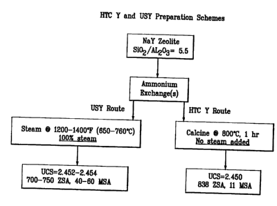
Figure 2 gives the catalyst preparation scheme and compares the surface area
s and UCS properties of HTC Y with 5.5 Si021A1203 ratio with that of a
conventionally
prepared ultrastable Y at the same Si021A1203. At nearly equivalent UCS
ranges, the
HTC Y exhibited a 50-150 m2g-' ZSA increase over the USY zeolite.
CA 02354518 2001-06-12
WO 00/20332 PCT/US99/22592
14
The XRD patterns of HTC Y and USY having similar Si02/AIZOa ratios are set
out in Tables 2 and 3, respectively, using Cu K alpha radiation. The peaks at
higher
28 (>10 28) were reduced in peak height relative to the low angle peak (~6 2 )
for
the HTC Y as compared to the USY. Accordingly, the peak height ratios for HTC
Y
s and USY are significantly different, where peak height ratio is defined as:
Ratio PH = height of XRD peak at >10°28
height of XRD peak at ~6° 28
io , Table 2 below (calculated from the XRD data obtained for the HTC Y and
USY) gives the calculated peak height ratios for 8 main peaks between 10-35 2
.
From Tabte 2, it can be inferred that HTC Y is a significantly different and
structurally
unique material from USY based on the calculated peak height ratios.
CA 02354518 2001-06-12
WO 00/20332 PCT/US99/22592
Table 2
Calculated XRD Peak Ratios
HTC Y
Pe k no. 2-Theta angle Peak Heicrht RatiopH
1 6.321 1377
2 10.292 239 0.174
3 12.069 154 0.112
4 15.865 ~ 298 0.216
5 18.925 131 0.095
6 20.610 156 0.113
7 23.922 228 0:186
8 27.356 131 0.095
9 31.740 93 0.068
Peak no. 2-Theta angle Peak Height RatiopH
1 6.184 1550
2 10.141 420 0.271
3 11.905 311 0.201
4 15.682 586 0.378
5 18.724 261 0.168
6 20.409 311 0.201
7 23.714 457 0.295
8 27.125 262 0.169
9 31.502 223 0.144
The same two NH4Y zeolites from Example 1 were calcined at high
temperature without first preheating at 250°C. Table 3 gives the data
obtained at
s temperatures from 600-900°C and comparative data at the same
temperature from
Example 1. The data indicate the preheating step to be critical in obtaining a
crystalline product with reduced UCS. For the 3.5 Si02lAiZOs ratio zeolite,
crystal
CA 02354518 2001-06-12
WO 00/20332 PCT/US99/22592
16
collapse was seen at 600-800 C for the HTC Y without preheating and lower
stability
and lesser UCS reduction was seen for the 5.5 Si02/A1203 ratio zeolite. These
data
indicate preheating of the zeolite prior to HTC to be an important step in
producing the
desired product.
s
Table 3
Effect of Preheating Zeolite
Parent: NH4Y, Si02/AI203 = 3.5, 2.16% Na
2.498 nm UCS, 873 ZSA, 19 MSA
600oC 600oC
UCS, nm 2.491 collapse
ZSA, m2g'' 881 283
MSA mZg'' 7 20
700oC 700oC
UCS, nm 24.83 collapse
ZSA m2g'' 897 237
MSA m2g'' 9 16
800oC 800oC
UCS,nm collapse collapse
ZSA mZg'' 3 256
MSA m2g'' 2 8
CA 02354518 2001-06-12
WO 00/20332 PCT/US99/Z2s92
17
Parent: NH4Y, Si02/A1z03 = 5.5, 2.45%.Na
2.468 UCS, 937 ZSA, 7 MSA
Preheated' No Preheat
700oC 700oC
UCS,nm 2.458 24.82
ZSA m2g' 891 855
MSA m2g'' 10 9
800oC 800oC
UCS, nm 2.450 24.59
ZSA m2g'' 838 860
MSA mzg'' 11 11
900oC 900oC
UCS,nm 2.453 collapse
ZSA mZg'' 852 55
MSA m2g'' 14 8
Three NaY zeolites, having Si02/A1203 ratios of 3.5, 4.2, and 5.5, were
subjected to high temperature calcination at 700-900°C. In all cases,
no steps were
taken to reduce zeolite Na levels by ion-exchange; preheating of the zeolites
was
s done at 250°C for 1 hr prior to HTC.. Data are given in Table 4 and
show that, in all
cases, very little reduction in UCS was observed over the range of HTC
temperatures
(0.003-0.004 nm reduction). This example shows the significance of zeolite
sodium
level for producing the desired HTC Y product.
CA 02354518 2001-06-12
WO 00/20332 PCT/US99/22592
18
Table 4
Effect of Sodium Content
NaY, SIO~IAI2O3 = 3.5
Calcination
Temp.
Parent 700oC 800oC 900oC
Na, pct.wt7o 10.70
UCS,nm 2.491 2.490 2.488 collapse
ZSA m2g' 872 854 814 3
MSA m2g'' 8 4 8 1
NaY, SiO~/AI20s = 4.2
Parent 7p0oC 800C 900oC
Na, wtr6, 10.22
UCS,nm 2.48 2.478 2.476 collapse
ZSA m2g'' 902 869 858 0
MSA mZg'' 8 9 8 4
NaY, SiO~lAl24s
Parent 700oC 800oC 900oC
Na, wt~ 6.726
UCS,nm 2.468 2.464 2.464 2.464
ZSA m2g'' 904 854 802 152
MSA mZg'' 3 7 6 1