Note: Descriptions are shown in the official language in which they were submitted.
CA 02354615 2001-06-14
WO 00/35787 PCT/US99/29888
-1-
DIFFERENTIAL IMPULSE CONVEYOR WITH LINEAR MOTOR DRIVE
Field of the Invention
The present invention relates to a differential impulse conveyor for moving
goods along a
conveyor tray. More particularly, this invention relates to an improved drive
mechanism which utilizes
an electrically powered linear motor forpowering movement of the differential
impulse conveyor tray with
respect to a conveyor base. A related invention involves a linear connector
for interconnecting a stationary
member and a movable member, with the connector being pivotally connected to
one of the members.
The connector includes a linear bearing for achieving straight line motion
rather than arcuate motion of
the movable member.
Background of the Invention
Various types of conveyors are available which each employ an elongate,
slightly downwardly
inclined tray or pan having a planar surface for transporting goods thereon.
These types of conveyors are
preferred in various industries since the goods being transported along the
tray need only engage a unitary
tray during the conveying operation, and since the tray may be easily cleaned.
Conveyors of this type have
been used for decades and include those commonly referred to as reciprocating
conveyors, shaker
conveyors, or vibratory conveyors.
Differential impulse conveyors may also use a slightly downwardly inclined
tray, but altematively
may use a horizontal tray or slightly upwardly inclined tray. Differential
impulse conveyors, which are
sometimes referred to as linear motion conveyors, are operationally
distinguishable from vibratory
conveyors because the tray is moved slowly forward to convey the goods with
respect to the tray, and then
is moved rearward at a high return speed so that the goods slide along the
tray, thereby effectively
transporting the goods along the conveyor tray. A significant advantage of
differential impulse conveyors
is that these conveyors do not tend to damage fragile goods. Moreover, a
differential impulse conveyor
does not require gravity to move goods along the tray, and accordingly the
tray supporting surface may
CA 02354615 2001-06-14
WO 00/35787 PCT/US99/29888
-2-
be horizontal or may even be inclined upwardly. Accordingly, differential
impulse conveyors have gained
increased acceptance in recent years.
The drive mechanism for a differential impulse conveyor generates repeated
acceleration and
deceleration of the tray. Since the forward acceleration is less than the
rearward acceleration, the goods
move with the tray when the tray moves forward, and slide with respect to the
tray when the tray moves
rearward. Early types of drive mechanisms for achieving this motion in a
differential impulse conveyor
included a plurality of weights which were moved back and forth to obtain the
desired movement of the
tray. These inertia drive systems impart high loads to the conveyor support
structure or base, and thus
typically require a heavy and expensive support structure for the conveyor.
These inertia drive systems
undesirably require a fair amount of startup time before the motor driving the
weights causes the tray to
move in its desired manner, and similarly result in tray movement for a period
of time after the drive motor
is de-energized. Also, these inertia drive mechanisms are costly and
complicated, and frequently have high
maintenance costs.
Another type of drive mechanism for powering a differential impulse conveyor
utilizes a power
source which cooperates with mechanical components which directly move the
tray. One such
arrangement, as disclosed in U.S. Patent No. 5,351,807, employs an angled
universal drive and a speed
reducer to achieve the desired tray movement. Other drive systems for powering
a differential impulse
conveyor are disclosed in U.S. Patent No. 5,794,757. One drive mechanism
recently introduced to the
marketplace employs a plurality of eccentrically mounted pulleys. A crank arm
interconnects one of the
pulleys and a tray support arm to drive the conveyor tray slowly forward and
then quickly backward. The
systems disclosed in the above two patents have significant advantages over
inertia drive systems for
powering a differential impulse conveyor. These drive systems have the ability
to substantially
instantaneously achieve the desired tray motion when the drive unit is
started, and similarly
instantaneously stop the tray motion when the drive unit is stopped. This is a
significant advantage of
these drive units compared to the inertia drive mechanisms, and allows the
differential impulse conveyor
to be reliably used for cross-feed applications. The size and expense of these
latter described drive
systems, as well as the number of moving parts, nevertheless restricts the
acceptability of differential
CA 02354615 2001-06-14
WO 00/35787 PCT/US99/29888
-3-
impulse conveyors, particularly in applications wherein the size and cost of
the drive system are significant
factors to the customer.
The disadvantages of the prior art are overcome by the present invention. An
improved
differential impulse conveyor with a linear drive mechanism is hereinafter
disclosed. The drive
mechanism has few moving parts, and in many applications requires less space
and cost than other drive
mechanisms. An improved connector is also disclosed for pivotally
interconnecting a stationary member
and a member movable with respect to the stationary member such that the
movable member reciprocates
in a straight line path rather than in an arcuate path.
CA 02354615 2007-06-01
-4-
Summary of the Invention
A differential impulse conveyor includes a tray movable in a forward direction
to move
with the goods and in a backward direction to slide goods along the tray. An
electrically powered
linear motor moves the tray in the forward direction and in the backward
direction. The linear
motor has an armature linearly movable with respect to a stator in a
reciprocating manner to move
the tray. A pair of tray support arms interconnect a conveyor base and the
tray. The armature of
the linear motor may be connected to either one of the tray support arms or
directly to the tray.
In a preferred embodiment of the invention, each tray support member is
pivotally
connected to a lower end to the conveyor base and is pivotally connected at an
upper end to the
tray. The electrically powered motor stator may have a plate-like
configuration, and the armature
may have a similar configuration. Electrical power supplied to the motor thus
linearly moves the
armature with respect to the stator, and thereby moves the tray with respect
to the base. For
differential impulse conveyors with relatively large trays, a counterweight
may be provided
movable in a backward direction during forward movement of the tray and in a
forward direction
during backward movement of the tray.
A connector for interconnecting a stationary member and a movable member
linearly
movable in a straight line path is also provided. A pivot at one end of the
connector is connected
to one of the stationary and movable members. A specially designed curved end
surface on the
connector and a specially designed curved contact surface on the other of the
stationary and
movable member result in rolling engagement of engaging curved surfaces to
result in straight line
travel of the movable member.
Accordingly, the present invention seeks to provide an improved differential
impulse
conveyor utilizing an electrically powered linear motor to move the tray in a
forward direction and
in a backward direction. A related aspect of the invention is to increase the
acceptability of
differential impulse conveyors in various applications by providing a conveyor
drive mechanism
which is highly reliable and has a relatively low cost.
Further, the invention seeks to provide a connector for interconnecting a
stationary
member and a movable member, with the connector being pivotally connected at
one end to one
CA 02354615 2007-06-01
5-
of the stationary member and movable member. The opposing end of the connector
has a curved
end surface with a radius positioned along the pivot axis. A curved contact
surface is provided on
the other of the stationary member and the movable member, which contact
surface has a radius
twice that of the end surface. This curved contact surface engages the curved
end surface to
provide for linear motion of the movable member with respect to the stationary
member.
It is a feature of the invention to provide a controller for regulating the
linear drive motor
of a differential impulse conveyor, such that the cycle rate of the linear
motor is controlled to
regulate the travel speed of the product moving along the reciprocating tray.
Another feature of
the present invention is that the linear motor conveyor is well adapted for
use to drive a
differential impulse conveyor tray forward and backward, with the tray being
supported on a pair
of arms pivotally connected to the conveyor tray. High reliability for the
conveyor may be
enhanced by eliminating or at least substantially reducing the number of
linear bearings which
guide tray movement with respect to the base in both the forward and backward
directions.
Another significant feature of this invention is that the number of movable
parts required
to drive the tray of a differential impulse conveyor may be reduced compared
to prior art drive
mechanisms. Both the size and the cost of the drive system for powering the
differential impulse
conveyor may also be reduced, thereby significantly increasing the
applications in which a
differential impulse conveyor is a preferred type of transport system for the
goods.
Yet another feature of the invention is that differential impulse conveyor may
include a
pair of supports each forming an improved linear bearing with a specially
designed contact surface
in the base of the conveyor, such that each support may be pivotally connected
to the tray while
the axis of this pivotal connection remains at the same elevation during the
forward and rearward
movement of the tray.
An advantage of the present invention is that another linear drive motor may
be used to
power a counterweight which opposes movement of the tray. Alternatively, a
linkage mechanism
may be provided so that the counterweight and the tray are driven by the same
linear motor, with
a counterweight moving in the opposite direction of the tray.
CA 02354615 2007-06-01
, . ..
6-
Yet another advantage of this invention is that the linear motor drive system
is able to
substantially immediately obtain the desired motion of the conveyor tray upon
activation of the
linear motor, and similarly stops tray motion substantially immediately upon
deactivation of the
linear motor, such that the conveyor is well suited for various applications.
Another significant advantage of the present invention is that the cost of
linear motors is
relatively low. The selected linear motor may either utilize permanent magnets
or an electrical coil
or winding on both the stator and the armature. A linear motor with a stator
coil encircling an
armature may be used. Alternatively, a linear motor may have either a flat
plate stator and a flat
plate armature, or a curved plate stator and a curved plate armature.
These and further aspects, features, and advantages of the present invention
will become
apparent from the following detailed description, wherein reference is made to
the figures in the
accompanying drawings.
CA 02354615 2001-06-14
WO 00/35787 PCT/US99/29888
-7-
Brief Description of the Drawings
Figure 1 is a side view of one embodiment of the differential impulse conveyor
according to the
present invention utilizing linear motors with an armature circumferentially
encircling a reciprocating
shaft.
Figure 2 is a side view of a alternate embodiment of a conveyor similar to the
conveyor shown
in Figure 1 but modified such that the linear motor includes a curved shaft
which reciprocates in an arc
along the shaft centerline.
Figure 3 is a side view of another embodiment of a differential impulse
conveyor utilizing a linear
motor having a curved plate armature and a curved plate stator.
Figure 4 is a left end view of the embodiment shown in Figure 3.
Figure 5 is a side view of an alternate embodiment of a conveyor similar to
the conveyor shown
in Figures 3 and 4 but modified with a counterweight linkage.
Figure 6 is a side view of another embodiment of a differential impulse
conveyor utilizing a motor
having a flat plate armature and a flat plate stator.
Figure 7 is a right end view of the embodiment shown in Figure 7.
Figure 8 is a side view of another embodiment of a differential impulse
conveyor having a flat
plate armature, a flat plate stator, and tray support members with lower
linear bearings.
Figure 9 is a detailed end view of a tray support or other connector with a
lower linear bearing
as generally shown in Figure 8.
Figure 10 is a side view of the lower linear bearing shown in Figure 9.
Figure 11 is a side view of another embodiment of a differential impulse
conveyor with a linear
motor having an armature circumferentially surrounding a reciprocating shaft
and utilizing conventional
linear bearings to support the tray.
Figure 12 is a left end view of the differential impulse motion conveyor shown
in Figure 10.
Figure 13 is another embodiment of a differential impulse conveyor with a
motor having a flat
plate armature and flat plate stator, and with conventional linear bearings
supporting the tray.
Figure 14 is a left end view of the differential impulse conveyor shown in
Figure 13.
CA 02354615 2001-06-14
WO 00/35787 PCT/US99/29888
-8-
Detailed Descrigtion of Preferred Embodiments
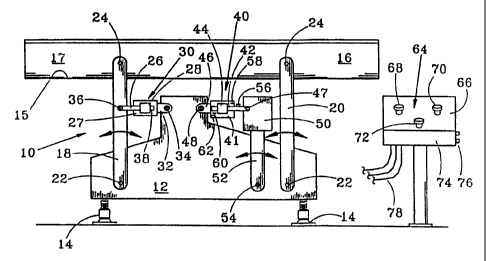
Figure 1 depicts one embodiment of a differential impulse conveyor 10
according to the present
invention powered by a linear motor 30. The differential impulse conveyor
includes a base 12, which is
schematically shown in Figure 1 as being secured to the floor by a plurality
of machine feet 14, each of
which is selectively adjustable so that a base 12 may be precisely leveled
and, if desired, the inclination
of the pan 16 supported on the base may be altered. Each of the machine feet
14 may have various
configurations, and for applications wherein the differential impulse conveyor
is used in -the food
processing industry, each machine foot 14 may be of the type shown in U.S.
Patent No. 5,842,678.
The pan 16 is of a conventional type used on differential impulse conveyors,
and includes a tray
floor 15 for supporting the goods being moved along the tray and a pair of
tray sides 17. As shown in
Figure 1, forward movement of the goods is to the right, and thus the tray 16
moves forward to move
goods in that direction, then the tray more quickly moves backward so that the
goods slide along the tray,
thereby effectively moving the goods forward with respect to the reciprocating
tray. Those skilled in the
art will appreciate that the forward and backward cycle of the tray ideally
occurs rapidly for most
applications, and typically is in the range of from 100 to 250 cycles per
minute. Maximum travel rate for
the product is typically achieved at cycle rates of about 200 cycles per
minute.
As shown in Figure 1, the tray 16 is supported by tray support members 18 and
20. For the type
of tray support members shown in Figure 1, at least two such support members
are necessary, although
in a preferred embodiment a rearward left-side and a rearward right-side tray
support member 18 are
provided, and a forward left-side and a forward right-side tray support member
20 are also provided. Less
desirably, a rearward support under the conveyor tray and centrally located
between the sides of the tray
16 and another similarly located forward support member could be used. Each of
the tray support
members 18 and 20 is pivotally connected at this lower end to the base 12 so
that each tray support
member pivots about a respective axis 22. Each tray support member is
similarly pivotally connected to
the tray 16, and ideally to either a left-side wall or right-side wall of the
tray so that it pivots about an axis
24 with respect to the tray 16. The forward and backward movement of the tray
16 is typically 2 inches
or less, and in most applications is from about 1.5 inches to 2 inches.
Accordingly, it should be understood
CA 02354615 2001-06-14
WO 00/35787 PCT/US99/29888
-9-
that the angle of pivotal movement of each of the tray support members with
respect to the base 12 about
the axis 22 is very slight, and similarly the angular member of each tray
support member with respect to
the reciprocating pan 16 about axis 24 is slight.
The electrically powered linear motor 30 shown in Figure 1 includes a stator
27 which is secured
to the base 12, and a reciprocating armature 26 which, for the embodiment
shown in Figure 1, is secured
to one of the tray support arms or members 18. The opposing end 38 of the
armature thus reciprocates
within the stator 27. In a preferred embodiment, it should be understood that
a cross member (not shown)
may interconnect the left-side and right-side rearward tray support arms 18,
so that the armature 26 is
pivotally interconnected to the cross member, which in turn is then fixedly
connected at each end to a
respective one of the tray support members 18. Each of the linear motors
disclosed herein has the desired
capability of instantaneously starting and stopping the tray movement at its
desired speed, thus allowing
the conveyors to be reliably used for cross-feed applications.
The electrically powered motor 30 includes an electrically energized coil of
insulated wire 28
which produces a magnetic field within the coil. The magnetic field produced
by the coi128 may be used
to magnetize and thus attract the plunger or armature 26 to a position within
the coil and, in a commercial
embodiment, the motor may include two such coils each of which attract a
respective portion of the
armature 26. Electricity to each of the coils may be alternated, so that this
action produces the linear
reciprocation of the armature 26. The round linear motor 30 thus may
functionally be equivalent to a pair
of in-line solenoids arranged to reciprocate a plunger or armature 26. In an
alternate embodiment, one or
more electrical coils may also be provided on the armature, in which case the
motor 30 closely resembles
a conventional electric motor which outputs a rotary shaft, but in this case
the motor 30 outputs linear
reciprocating motion of the armature or plunger 26. It should be understood
that the terms "stator" and
"armature" as used herein are broadly defmed to refer to the stationary
component and the movable
component of a linear motor. For the embodiment shown in Figure 1, the linear
motor is a simple "round"
linear motor with one moving part, namely the armature 26, and typically
includes at least a pair of intemal
linear bearing to guide the linear movement of the armature. The motor 30 may
also include position
sensors so that the actuation of the coils may be properly timed or sequenced.
A suitable round linear
CA 02354615 2001-06-14
WO 00/35787 PCTIUS99/29888
-10-
motor is commercially available from various manufacturers, including
California Linear Devices, Inc.
A particular advantage of the round linear motor 30 as shown in Figure 1 is
that the coils circumferentially
surround the armature 26 which passes through the center of each coil, thereby
eliminating or at least
substantially reducing forces acting on the armature which are not linear,
i.e., which are not aligned with
the central axis of the armature 26.
Even though the angular movement of the tray support arm 26 with respect to
the base 12 is slight
during operation of the motor 30, the linear bearings in the motor 30 would be
destroyed quickly if the
motor stator were rigidly secured to the base 12 and the motor armature were
rigidly secured to the support
18. Accordingly, the motor stator 27 is secured to stator support 32, which in
turn is pivotally secured to
the base 12 to rotate about pivot axis 34. The pivotal connection between the
support 32 and the base may
take various forms, such as a conventional clevis arrangement. Similarly, the
end of the armature 26 is
pivotally connected to the tray support 18 or to the cross member (not shown)
between the pair of tray
supports 18 so that a pivotal connection about axis 36 is provided. The
pivotal connection at each end of
the motor 30 to the base and the tray support member 18 thus allow the
armature 26 to move in a linear
manner even though the tray support member 18 is pivoting back and forth about
the axis 22.
The pivotal connection between the base 12 and the support member 18, and
between the support
member 18 the tray 16, may be obtained using commercially available rubber
bushings. Suitable bushing
for this application is available from Great Lakes Bushings, Inc. in Kenosha,
WI., Model Nos. GL 030 or
GL- 1. This type of bushing at the ends of each tray support member provide
very low wear and very high
reliability, which is very important in this application in view of the high
number of forward and backward
cycles of the tray 16.
The cycle of the linear motor may be regulated by a controller 74, which in
turn may receive
signals from position sensors on the motor. Controller 74 thus outputs
electrical power via lines 78 to the
coils in the motor 30. A control station 64 may be provided with various
controls for regulating the cycle
of the motor. A control adjustment knob 68 may thus be used to control the
power to one coil in the motor
and thus control the forward speed and the forward acceleration of the tray
16. A similar adjustment knob
70 may be used to control the electrical power to another coil and thereby
regulate the velocity and
CA 02354615 2001-06-14
WO 00/35787 PCT/US99/29888
-11-
acceleration of the tray 16 during the return or backward movement of the tray
16. For a tray of a given
weight, it is envisioned that each of these forward acceleration and backward
acceleration curves may be
optimized with the controller to produce the desired velocity or acceleration
curve, as discussed more fully
in U.S. Patent No. 5,794,757. A graph plotting the forward and rearward
velocity of the conveyor may
thus illustrate a sinusoidal motion that provides a relatively slow forward
and fast backward movement,
with the backward velocity being approximately 2.6 times the maximum forward
velocity in order to
provide travel rates of goods along the conveyor at speeds of up to 40 feet
per minute. A preferred
velocity curve for a given tray may also be maxinzized for a specific tray
inclination since, as previously
noted, the differential impulse conveyor of the present invention may be used
to reliably convey goods
along the tray regardless of whether the tray 16 is angled slightly
downwardly, is horizontal, or is angled
slightly upwardly.
Another control knob 72 is provided for regulating the cycle time of the
forward and reverse
motions of the conveyor, and thereby regulates the velocity of the goods as
they move forward with
respect to the reciprocating tray 16. Accordingly, the user may adjust the
speed of the goods moving along
the tray by regulating the knob 72, with the adjustment knob 68 and 70 remain
unchanged. Computer
outlets 76 may be provided so that a portable computer controlled by a
conventional keyboard may input
or retrieve data stored in the controller, and may alter the operation of the
controller 74 in response to
operator signals. The controller 74 may thus control electrical power along
lines 78 which drive the
motors 30 and 40. It should be understood that the operator control station 64
as shown in Figure 1
includes a control panel 66 which is structurally independent of the base 12
of the differential impulse
conveyor. In many applications, the controller 74 as well as the adjustment
devices 68, 70, and 72 may
be mounted on a panel 66 which is directly supported by base 12 of the
conveyor. For a differential
impulse conveyor with a pan which is relatively small and thus lightweight, a
counterweight need not be
provided to offset the motion of the tray 16 in order for the differential
impulse conveyor to have a long
life. For applications wherein the pan weight is in excess of approximately 20
pounds, however, generally
it is desired to provide a counterweight which moves backward during forward
motion of the tray, and
similarly moves forward during backward motion of the trays, thereby reducing
the net forces acting on
CA 02354615 2001-06-14
WO 00/35787 PCT/US99/29888
-12-
the base and ensuring the smooth running operation for the conveyor. As shown
in Figure 1, the
counterweight 50 is thus optionally provided on a support 52 which is
pivotally connected at 54 to the base
12. Another linear motor 40 similar to the linear motor 30 previously
described is provided for powering
the counterweight, with this motor 40 being controlled in the same manner as
motor 30. This linear motor
40 thus includes a stator 41 which is fixedly secured to support 46, which is
pivotally connected to the base
12 at 48. The armature 42 extends through one or more coils 44, with the
extending end of the armature
being connected to the counterweight 50 to pivot about pivot axis 47. Figure 1
also conceptually illustrates
a triggering device 56 mounted on the armature 42 and a position sensor 58
mounted on the stator 41 to
output a signal in response to the position of the armature. The opposing end
of the armature may include
a similar triggering device 60 and another position sensor 62. The position
sensors 58 and 62 may thus
output signals to the controller 74 to assist in regulating operation of the
motor 40. Hall effect transducers
may be suitable position sensors for sensing the position of the armature with
respect to the stator.
Although not shown in Figure 1, it is understood that the linear motor 30 may
similarly include such
position sensors, which either may be integral in the linear motor as
manufactured, or may be added as an
extra feature to a linear motor.
Movement of the counterweight 50 in response to motor 40 thus effectively
eliminates or at least
substantially reduces the vibration in the differential impulse conveyor which
otherwise would occur due
to the rapid acceleration and deceleration of a heavy pan 16. Another rubber
bushing of the type
previously described preferably is used to pivotally mount the counterweight
support 52 with respect to
the base 12.
A significant advantage of a differential impulse conveyor as shown in Figure
1, and as discussed
in many of the following embodiments, is that the tray or pan is supported
with respect to the base without
the use of linear bearings. The use of rubber bushings rather than linear
bearings contributes to the long
life of the conveyor, and significantly reduces the conveyor maintenance
costs. One of the disadvantages
of the embodiment shown in Figure 1 is that linear bearings, although not
depicted, are provided within
the motors 30 and 40 to guide movement of the armature with respect to the
stator. The operation of a
conventional linear motor is such that these internal bearings may have a
suitable life in many linear motor
CA 02354615 2001-06-14
WO 00/35787 PCTIUS99/29888
- 13-
applications, since these linear motor bearings are generally intended for use
over approximately
100 niillion inches of travel of the armature with respect to the stator. When
used in a differential impulse
conveyor, however, this high linear travel may be obtained in 8 to 10 months
of conveyor life, which in
many applications is unacceptable.
Figure 2 depicts a portion of a differential impulse conveyor 80 which is
similar to the
embodiment shown in Figure 1. Accordingly, only those portions which
distinguish Figure 2 from Figure
1 are discussed below. In the Figure 2 embodiment, tray support arm 18 is
reciprocated by a linear motor
82 which includes a stator 83 housing one or more coils 84 and an armature 86.
Rather than having a
straight axis, the armature 86 has a curved axis 87, with the radius of
curvature being such that its center
is substantially along the pivot axis 22. The base 12 as shown in Figure 2
includes a rigid support 13, and
the stator 83 is rigidly fixed to the rigid support 13 by a connecting bracket
88. The curved armature 86
similarly may be rigidly secured to the tray support member 18 or to the cross
member which interconnects
the left-side and right-side tray support members. The curvature of the
armature 86 is thus controlled so
that neither the stator nor the armature need be pivotally connected to the
base and the tray support,
respectively. For this application, linear bearings otherwise conventionally
provided in a round linear
motor may thus be eliminated or, if such linear bearings are provided, their
life is significantly increased
since the axis of the armature is otherwise fixed relative to the stator. The
embodiment as shown in Figure
2 may thus have the advantage of a longer life compared to the embodiment as
shown in Figure 1. The
Figure 2 embodiment may also eliminate the pivotal connection of the round
linear motor with the base
and the tray support member, although if desired a pivotal connection may
still be made for purposes of
alignment, at which time the position may be locked in place. The embodiment
as shown in Figure 2 has
the same advantage of the embodiment shown in Figure 1, in that the round
motor produces no significant
forces on the armature other than the desired linear motion forces which
result in reciprocating movement
of the armature with respect to the stator. For the Figure 2 embodiment, this
reciprocating motion of the
armature with respect to the stator is still linear, although in this case the
linear motion is along a curved
or arced path rather than in a straight line. In the Figure 2 embodiment, it
should be understood that a
counterweight and another linear motor sirnilar to motor 82 for separately
driving the counterweight may
CA 02354615 2001-06-14
WO 00/35787 PCT/US99/29888
-14-
be provided, although the additional motor and the counterweight are not
depicted in Figure 2 since its
operation will be understood by those skilled in the art in view of the
disclosure in Figure 1. Also, it
should be understood that in Figure 2, as well as in the remaining figures
discussed subsequently, the same
reference numerals are used to describe components which functionally are
similar to components
previously described. Also, Figure 2 and the remaining figures discussed
subsequently depict the conveyor
leveling feet 14 shown in Figure 1. Such leveling feet are preferable, but may
not be required.
Figures 3 and 4 depict an alternate embodiment of a linear motion conveyor 90
according to the
present invention. In the Figure 3 embodiment, the pair of tray support
members 18 are driven by a linear
motor 95 which utilizes one or more plate-like linear motor stators 92 and one
or more similar linear motor
armatures 94, with each of the stators and armatures being manufactured so
that the curve of the plate has
a radius with a center spaced along the pivot axis 22. A similar linear motor
97 may be used to drive the
counterweight 50, with this linear motor having a stator 98 secured to the
base 12 at its ends 100 and 102,
and an anmature 104 secured to the top of the counterweight 50. The linear
motor 95 thus reciprocates the
support member 18 while the linear motor 97 reciprocates the counterweight 50.
Counterweight 50 is
supported on counterweight support member or anm 52, which pivots with respect
to the base 12 about axis
54. The curved plate stator 98 and the curved plate armature 104 similarly
have a radius with a center
along the counterweight pivot axis 54. A left-side and a right-side
counterweight support member 52 may
be provided for pivotally supporting the counterweight 50 with respect to the
base 12. When the tray or
pan 16 moves in the forward direction, the counterweight 50 moves in the
reverse direction, and when the
tray 16 moves in the backward direction, the counterweight 50 moves in the
forward direction. Again, the
pivot connections between the support members 18, 20 and 52 about the
respective pivot axes 22, 24 and
54 may be provided by rubber bushings.
Referring to Figure 4, the curved plate armature 94 for the motor 95 is shown
mounted to a cross
piece 96 which interconnects the pair of pan support member 18. The
counterweight supports 52 are not
depicted in Figure 5 since they are hidden by the tray support members 18.
Each of the curved plate
stators for the motors 95 and 97 may include sections spaced along the
curvature of each plate to attract
corresponding sections in the armature. Linear motors with plate-like stators
and plate-like armatures are
CA 02354615 2001-06-14
WO 00/35787 PCT/US99/29888
- 15-
manufactured by Anand Corp. or Trilogy Systems Corp. The stators and armatures
as shown in Figure
3 may thus be specially manufactured to have the desired curvature so that the
gap between each stator and
the respective armature remains constant during reciprocation of the tray 16
or the counterweight 50.
Figure 3 also illustrates that the triggering devices 56 and 60 as well as the
respective position
sensors 58 and 62 may be provided on the armature and the frame, respectively,
for sensing the position
of the counterweight 50. These triggering devices and sensors would thus
functionally operate in the
manner similar to the triggering devices and sensors previously discussed, and
in one embodiment may
be Hall effect sensors. Similar triggering devices and sensors may be provided
on the armature and the
stator of the motor which drives the tray, or alternatively may be provided on
the armature of the motor
driving the tray and the base 12. In yet another embodiment of the invention,
the position sensors may
be provided on any one of the tray supports 18, 20 or any one of the
counterweight supports 52 and on the
base 12. Although only shown for the embodiment in Figure 3, it should thus be
understood that position
sensors may be provided for sensing the respective position of the armature
with respect to the stator for
any of the linear motors discussed herein.
Figure 3 also depicts a forward stop 106 and a backward stop 108 each for
limiting forward
movement and backward movement of the tray, respectively. When the motor 95 is
energized, the motor
itself directly controls forward movement and backward movement of the tray
support arms 18, and thus
the forward travel and backward travel of the tray 16. When the motor 95 is
inactive, the stops 106 and
108 thus ensure that the travel of the pan 16 is limited by engagement of the
member 18 with one of the
stops 106, 108, thereby ensuring that the tray does not drop below a selected
height. Each of the stops 106
and 108 may be secured to the base 12 for engagement with one of the tray
support arms 18, 20. Each stop
may be adjustable within selected limits by a conventional threaded bolt
arrangement. Although only
shown for the Figure 3 embodiment, it should be understood that similar stops
may be used on all of the
embodiments discussed herein. Also, the stops may be provided at various
positions and may directly
engage the support arms, the motor armatures, or the tray or counterweight,
respectively.
Figure 3 illustrates another feature of the counterweight 50 which, although
only shown for the
Figure 3 embodiment, may also be used for any of the counterweights discussed
herein. As shown in
CA 02354615 2001-06-14
WO 00/35787 PCT/US99/29888
-16-
Figure 3, the counterweight 50 includes a plurality of plates, which are
simplistically depicted as plates
50A, 50B, and 50C, respectively. Each of these plates may be easily added and
removed from the
remaining weight of the counterweight by a conventional mounting arrangement,
such as hooks, bolt
supports 51, or other conventional supporting member. The weight of the
counterweight may thus be
easily varied by adding or deleting additional plates 50A, 50B and 50C to any
end, side, or bottom of the
counterweight assembly. This allows the weight of the counterweight assembly
to easily match to the
weight of the tray, so that the same basic counterweight assembly may be used
for different sized trays,
with the addition of plates 50A, 50B, and 50C for the heavier trays.
The embodiment as depicted in Figures 3 and 4 has significant advantages. Both
the height and
the size of the drive unit may be minimized so that, if desired, the tray 16
may be mounted closely adjacent
the floor, with the tray support members 18 and 20 having a height of, e.g.,
12 inches. The linear motor
95 is positioned directly between the pair of tray supports 18. By centering
each of the linear motors 95
and 97 directly over the pivot points of the support member which that motor
drives, the rigidity of the
assembly and the accuracy of the drive units to reciprocate the tray or the
counterweight are maximized.
The tray 16 and the drive unit 95 are structurally independent, thereby
allowing the tray to be formed as
a simple sheet metal product without regard to the manufacture of the motor
95.
Each motor stator and armature as shown in Figures 3 and 4 may be formed from
plates having
a thickness of approximately'/. inch, so that the cost of the drive unit is
relatively low. The arrangement
as shown in Figures 3 and 4 thus eliminates all linear bearings, thereby
improving the reliability and useful
life of the differential impulse conveyor. The mounting of the tray is
simplified by the use of the pivotably
tray support members 18 and 20, and the reliability of the mounting
arrangement for these supports is
ensured by the use of rubber bushings at each pivot location, as previously
explained.
Another embodiment of the invention may include linear motors which are very
similar to the
linear motors 95 and 97, but in this case the stator plate and armature plate
each have a flat plate
configuration. Linear motors with flat plate stators and armatures are
commercially available, and this
embodiment thus may have a lower cost than the embodiment depicted in Figures
3 and 4. A disadvantage
of utilizing flat plate stators and armature instead of the curved plate
stators and armatures for the
CA 02354615 2001-06-14
WO 00/35787 PCT/US99/29888
-17-
embodiment otherwise shown in Figures 3 and 4, however, is that as the tray
and the counterweight
reciprocate in the forward and backward directions, the armatures will rise
and fall with each stroke
because of the swing radius on the support or arm to which each respective
armature is attached. This
rising and falling thus changes the air gap between the flat plate stator and
the flat plate armature, which
adversely affects the efficiency of the linear motor. In some applications,
however, the undesirable change
in the air gap may not be a significant detriment. If the tray 16 is mounted
closely adjacent the floor, the
length of the support members 18 and 20 may each be 12 inches or less, as
previously noted. For this
embodiment, the rise or fall of the armature during a fu112 inch stroke of the
pan should be less than 0.05
inches, which may be an acceptable air gap variation for this linear motor.
The size of the air gap variation
will of course depend on the vertical spacing between the lower pivotal
support connection and the
armature. For embodiments which utilize light pans and thus do not require a
high efficiency linear motor,
and for embodiments wherein the tray is mounted fairly close to the pivot
connection 22, this alternate
embodiment with flat plate linear motor stators and armatures may be
practical.
Figure 5 depicts another embodiment of a differential impulse conveyor which
is similar to the
Figure 3 embodiment, although in this case the differential impulse conveyor
110 includes a single linear
motor 95 which is used to drive both the tray 16 and the counterweight 50. The
curved plate armature 94
of the motor 95 is thus connected to the pair of support members 18, as
previously described. The
counterweight 50 is mounted on a pair of rear support members 52 and a pair of
front support members
53, as is the embodiment depicted in Figure 8 discussed subsequently. In this
embodiment, however, a
linkage mechanism 112 interconnects the reciprocating arms 18 with the
counterweight 50, so that a single
linear motor may be used to simultaneously achieve forward movement of the
tray during backward
movement of the counterweight, and backward movement of the tray during
forward movement of the
counterweight. The reverse linkage mechanism 112 for this embodiment includes
a link member 113
which is pivotally connected to the base 12 to oscillate about pivot point
114. Another link member 116
interconnects the arm 18 with the link member 113, with this link member 116
being pivotally connected
to the arm 18 to rotate about axis 118, and pivotally connected to the link
member 113 to rotate about axis
120. A similar link member 122 interconnects an opposing end of a link member
113 to the counterweight
CA 02354615 2001-06-14
WO 00/35787 PCT/US99/29888
-18-
50, with this link member 122 pivoting about axis 124 with respect to link
member 113 and pivoting about
axis 126 with respect to the counterweight 50. When the linear motor 95 drives
the arm 18 in the
backward direction, this backward motion rotates the link member 113 in a
counterclockwise direction as
shown in Figure 5, thereby pushing the counterweight 50 in the forward
direction. The use of the linkage
mechanism 112 thus eliminates the expense of an additional linear motor, and
further eliminates any
problem associated with synchronization between two motors. Although not shown
for the other
embodiments depicted, it should be understood that a similar linkage mechanism
may be used for each of
the embodiments discussed herein which disclose one motor for driving the tray
and another motor for
driving the counterweight. Also, it should again be emphasized that, for some
applications, the use of a
counterweight may not be required.
Figure 6 and 7 depict yet another embodiment of a differential impulse
conveyor 130 which
utilizes linear motors each with flat plate stators and armatures. In this
case, the linear motor 135 for
driving the tray includes a flat plate armature 132 which is secured to the
tray 16 such that the armature
132 moves substantially within a first vertical plane. The motor 135 includes
a flat plate stator 134 fixed
to the base 12 and aligned within a second vertical plane adjacent to but
spaced horizontally from the first
vertical plane. By vertically mounting the stator and the armature, the gap
between the stator and armature
during pivotal movement of the tray support arms 18 and 20 is not varied. The
arrangement as shown in
Figures 6 and 7 both eliminates the need for linear bearings, and allows for
the use of a flat plate stator and
armature without varying the gap between the stator and armature during
operation of the motor. The
relatively small vertical movement of the armature 132 with respect to the
stator 134 does not vary the air
gap between the armature 132 and the stator 138, and should have little effect
on the operation and
efficiency of the linear motor 135. A similar flat plate stator 13 8 and a
flat plate armature 136 may be used
to drive the counterweight 50, with the armature 136 being affixed to the
counterweight 50. The armature
136 is positioned within a third vertical plane spaced horizontally from both
the first and second vertical
planes.
It should be noted that for each of the curved plate or flat plate linear
motors, only one armature
and one stator are shown for clarity, although the invention envisions the use
of multiple armatures and
CA 02354615 2001-06-14
WO 00/35787 PCT/US99/29888
-19-
corresponding multiple stators to achieve better motor performance,
particularly for applications wherein
the motor drives a large tray 16. Also, a motor could include a single stator
and a pair of armatures on
opposing sides of the stator, with one armature driving the tray and the other
armature driving the
counterweight.
For the embodiment shown in Figures 6 and 7, the armature for the linear motor
is fixedly
connected to the tray 16, while for other embodiments discussed above, the
armature for the linear motor
is connected to one of the tray support members 18, 20 which pivotally
interconnect the base 12 with the
tray 16. It should be understood that, for many applications, it may be
advantageous to interconnect the
armature to one of the tray support members rather than to the tray, so that
the manufacture and
replacement of the tray is independent of the linear motor. In other cases,
however, the an.nature may be
fixed directly to the tray rather than to one of the tray support members 18
and 20. This latter arrangement
is particularly well suited for the embodiment shown in Figures 6 and 7, as
well as the embodiment shown
in Figure 8 discussed subsequently, each of which use a flat plate linear
armature and a corresponding
stator. For the embodiments as shown in Figures 6-8, however, the flat plate
armatures altematively could
be mounted to one of the tray support members. Similarly, for the other
embodiments depicted wherein
the armature is attached to a tray support member, the armature could be
attached directly to the tray rather
than the tray support member, although those latter embodiments would not be
preferred for many
applications.
Figure 8 depicts yet another embodiment of a differential impulse conveyor 140
which utilizes
a linear motor 145 having a flat plate stator 142 and a flat plate armature
144. The flat plate stator 142 is
secured to the base 12, while the flat plate armature 144 is secured to the
tray 16. Also, a corresponding
flat plate stator 146 is secured to the base 12 and a flat plate armature 148
is secured to the counterweight
50 to drive the counterweight 50, as previously described. The tray 16 is
supported by tray supports 18
and 20 which are each pivotally connected at 24 to the tray 16. The
counterweight 50 includes four
support members 52, 53 each also pivotally connected to the counterweight 50.
For the Figure 8
embodiment, the desired constant air gap between the stator and the armature
is obtained by utilizing a
special linear bearing 150 at the lower end of the support members 18, 20, 52
and 53. As explained
CA 02354615 2001-06-14
WO 00/35787 PCT/US99/29888
-20-
subsequently, this linear bearing 150 thus allows the tray and the
counterweight to be reciprocated by the
respective motor without changing the air gap between the motor stator and the
motor armature, and also
allows the overall height of the conveyor to be significantly reduced.
Figures 9 and 10 illustrate in further detail the linear bearing 150 used in
conjunction with one
of the tray support members 20. The tray support member 20 is provided with a
pin 154 which
interconnects the tray support member 20 with the tray 16, and which allows
pivoting rotation of the tray
support member 20 with respect to the pan about axis 24. The lower end of the
tray support member 20
is provided with a curved end surface 152, with this curved end surface 152
having a selected radius such
that its center coincides with the pivot axis 24. The base 12 has a pocket 156
therein for receiving the
lower end of the tray support member 20, and a curved contact surface 158 is
provided for engagement
with the curved end surface 152. In accordance with the present invention, the
curved contact surface 158
has a radius which is twice the radius of the end surface 152, with the center
of this radius being spaced
directly above the axis 24 for the embodiment shown in Figure 9. As previously
noted, the tray 16 may
be moved in a purely horizontal manner during reciprocation of the tray
support members 18, 20 by the
linear motor in order to avoid a changing air gap between the motor stator and
armature. The linear
bearing 150 as shown in Figure 9 accomplishes this result by ensuring that the
end surface 152 rocks
slightly back and forth along the contact surface 158, but the controlled
radius of these contact surfaces
ensures that during this rocking action the pivot axis 24 moves horizontally
back and forth, and not in an
arcuate path. This desired result is achieved when the surface 152 rocks back
and forth on the contact
surface 158, and would not be achieved if these surfaces were in sliding
engagement. Accordingly,
Figures 9 and 10 depict two arrangements to ensure that no sliding action
occurs between the end surface
152 and the contact surface 158. Under one arrangement, the pair of guide ears
or pins 168 and 170
extend outward from the left and right sides of the support member 20. Each of
these pins move within
a respective slot 172, 174 affixed in the base 12, with this slot having a
central axis aligned with the pivot
access 24. As the support arm 20 rocks slightly back and forth on a contact
surface 158, the extending pins
168 and 170 are guided by the respective slots 172 and 174 to ensure that
these pins can only move in a
direction linearly toward the pivot axis 124. A horizontal centerline of the
pins 168 and 170 passes
_ _ _. _ . . . .., _ .
CA 02354615 2001-06-14
WO 00/35787 PCT/US99/29888
-21-
through the point of engagement of the surfaces 152 and 158 to ensure straight
line linear motion of the
axis 24. Accordingly, this guiding function served by the pins and slots
ensures that the end surface 152
will not be allowed to slide along the contact surface 158.
The lowermost ends 160 and 162 of the support member 20 thus straddle the
contact surface 158
and rock within the respective pocket 164 and 166 as shown in Figure 10. These
lower ends 160 and 162
provide support for the pins 168 and 170, although other arrangements could be
provided. By straddling
the central support 157 which includes the contact surface 158, these lower
ends 160 and 162 thus prevent
any undesirable movement of the support arm to the right or to the left as
shown in the Figure 10 view.
Figure 9 discloses another arrangement for ensuring that undesirable sliding
between the end
surface 152 and the contact surface 158 does not occur. For this embodiment,
the ears in the slots may
be eliminated, and instead both the end surface 152 and the contact surface
158 may be provided with
inter-engaging teeth 188 and 190, respectively. The mating engagement of these
teeth allow for the slight
rocking action necessary to accomplish the purposes of the invention, and
effectively prevent any
undesirable sliding ofthese surfaces. These inter-engaging teeth may be formed
as conventional gear teeth
on the end surfaces, or alternatively one of the gear teeth may be replaced
with a section of a timing belt
rigidly secured to that surface, with the teeth and the timing belt designed
to engage corresponding teeth
on the opposing end surface or on a mating timing belt. Although these teeth
may be used to prevent
undesirable sliding movement of the surface 152 with respect to the surface
158, the centerline contour
of these teeth nevertheless defme a curved surface which, as explained above,
satisfies the relationship
wherein the centerline of the teeth for the end surface 152 coincides with the
pivot axis 124, and the
centerline for the teeth 190 on the surface 158 has a radius twice that of the
surface 152. Also, those
skilled in the art should appreciate that the radius for the surfaces 152 and
158 depicted in Figure 9 are for
a very short support arm for clarity of the concept, and that when used as a
linear bearing for supporting
a tray of a differential impulse conveyor, these surfaces typically would have
a radius substantially greater
than that shown in Figure 9.
CA 02354615 2001-06-14
WO 00/35787 PCT/US99/29888
-22-
Figures 9 and 10 also depict an arrangement to eliminate the debris from
entering the pocket 156
which receives a lower end of the tray support member 20. Accordingly, a
conventional bellows 176,
which may be made from a rubber-like material, may be secured at one end or
four sides of the tray
support member 20, and secured at the other end to the base 12. The bellows
176 thus prevents material
from entering the pocket 156 for receiving the lower end of the support member
20.
Figures 11 and 12 depicting another embodiment of a differential impulse
conveyor 180
according to the present invention. For this embodiment, the tray 16 is driven
directly by a round linear
motor 30 as previously discussed, with the plunger or annature 26 being
connected directly to a bracket
184, which is fixed to the tray 16. Similarly, the round linear motor 40 is
directly connected to the
counterweight 50. The stators of both the motors 30, 40 may be secured to the
center support 182 which
is fixed to the base 12. The tray 16 is supported by two rearward arms 192 and
two similar forward arms
200. The rearward arms 192 are each mounted on a conventional linear bearing
190 to slide along fixed
shaft 188, which is supported by the spaced apart supports 186 secured to the
base 12.
Each of the tray supports 200 is similarly supported on a linear bearing 198
which slides along
the fixed shaft 196. Each shaft 196 is supported at its forward end by a
vertical support 194 each secured
to the base 12. As shown in Figure 11, both the counterweight 50 and the
linear bearing 198 may
optionally be spaced between the pair of vertical supports 194. As shown in
Figure 12, each of the linear
motors 30 and 40 may be centrally spaced between the tray support members 192.
Each of the linear bearings in the motors 30 and 40 may be of the type
conventionally provided
in round linear motors, or alternatively may be special linear bearings
designed for more rugged
application. The bearings 190 and 198 for the tray supports may also be
conventional linear bearings, and
may either be the type which utilizes a brass bushing or a ball bearing
construction. Suitable linear
bearings 190, 198 may be of the type manufactured by Thompson Industries, Inc.
in Port Washington,
N.Y.
One of the advantages of the embodiment shown in Figures 12 and 13 is that the
tray 16 may be
mounted closely adjacent the floor, since the drive mechanism requires very
little height or space. The
disadvantage of this embodiment, however, is the use of numerous linear
bearings both in the drive motor
CA 02354615 2001-06-14
WO 00/35787 PCT/US99/29888
- 23 -
and for the tray and counterweight supports. Commercially available linear
bearings may not have the
desired long life as do the rubber bushings which preferably replace the
linear bearings when the supports
are pivotally mounted. Even if linear bearings can be obtained with this
enhanced life, it is believed that
the cost of the linear bearings which will achieve a life comparable to that
of the rubber bushings as
disclosed herein will be significantly greater than the cost of the rubber
bushings.
For the embodiment shown in Figures 11 and 12, the tray connected member for
interconnecting
the linear motor and the tray is simply a bracket 184 which is secured to the
tray 16, and is also secured
to the armature of the linear motor. For other embodiments as discussed
herein, the tray connect member
which interconnects the tray 16 and the linear motor may include one or more
of the tray support members
18, 20 which in turn are pivotally connected to at least one end to base 12 or
the tray 16. For other
embodiments as discussed herein, the armature may be fixed directly to the
tray, in which case the only
tray connect member which interconnects the linear motor to the tray is the
securing member which
attaches the motor armature to the tray. Those skilled in the art will
appreciate that various bracket, clevis
or arm arrangements may be utilized for interconnecting the armature of a
linear motor to the tray 16.
Figures 13 and 14 depict yet another embodiment of a differential impulse
conveyor 210
according to the present invention. This embodiment utilizes a flat plate
linear motor 225 having a stator
226 secured to the spaced uprights 212 and 214, each affixed to the base 12.
The flat plate armature 224
for the drive motor 225 is secured to the crosspiece 232 which extending
between the tray support
members 222. The motor for driving the counterweight 50 includes a stator 228
also fixed to the supports
212, 214, and a flat plate armature 230 secured to the top of the
counterweight 50. Another cross member
234 extends between the linear bearings 216 and between the linear bearings
218 to support the
counterweight 50. A pair of fixed shafts 234 each extend between the supports
212, 214, and then
continues on to be supported by a respective forward support 194. Each of the
linear bearings 216, 220,
218 and 198 is thus linearly movable along a respective shaft 234 during
operation of the differential
impulse conveyor 210. Use of these linear bearings avoids the problem with the
varying air gap between
the flat plate stators and the flat plate armatures, but as previously noted
introduces the additional factors
of cost and poor service life for the use of linear bearings.
CA 02354615 2001-06-14
WO 00/35787 PCT/US99/29888
-24-
A particular advantage of the embodiment shown in Figures 13 and 14 is the use
of a linear motor
with a flat plate stator and armature, with each of the stator and armature
being centered over linear
bearings 220 to provide high rigidity and to precisely locate the armature
with respect to the stator. The
motor for driving the tray 16, and particularly the motor armature 224, is
connected to either the tray 26
or is connected to at least one of the tray support members 222. The linear
bearing 220 is positioned
horizontally in line with the linear motor (in a direction of movement of the
goods along the elongate tray)
such that the center of gravity of the armature 224 is vertically in line with
(directly over for the
embodiment shown) the linear bearing 220. This spacing of the motor armature
and the linear bearing
increases the likelihood of maintaining a substantially constant air gap
between the linear motor stator and
the linear motor armature. If the motor armature 224 is connected to one of
the pair of tray support
members, then that member, e.g., 222, is also vertically in line with the
armature. This vertical alignment
of the tray support member 222, the linear bearing 220 and the linear motor
thus contribute to the long
service life of the conveyor and also to the high efficiency of the linear
motor.
As shown in Figure 14, tray armature 224 may be attached to the crosspiece 232
extending
between the pair of tray support members 222 and thus between the pair of
linear bearings 220.
Accordingly, the linear motor for this embodiment has a benefit of being
structurally separate from the
tray, thereby allowing the drive unit and the tray to be manufactured and
replaced as separate components.
A significant advantage of the embodiment shown in Figures 13 and 14 is the
reduced overall height of
the drive unit, which is achieved by the use of the flat plate linear motor
and the linear bearing. The
tendency of a flat plate stator and a flat plate armature to pull together
during operation of the motor is thus
reduced by providing the supports 222 and the linear bearings 220 centered
with respect to the flat plate
stator and the flat plate armature. If desired, additional linear bearings
(not shown) may be used between
the armature and stator to maintain the constant air gap between the flat
plate stator and the respective flat
plate armature.
Linear bearings 150 as discussed herein may thus be used in conjunction with
the tray support
members 18, 20 and the armature support members 52, 53. In a less preferred
embodiment, it should be
understood that each of these support members may be pivotally connected at a
lower end to the base 12,
CA 02354615 2001-06-14
WO 00/35787 PCT/US99/29888
-25-
with the linear bearing 150 as shown in Figures 9 and 10 then used to
interconnect the upper end of each
support member with the tray 16 or the counterweight 50, respectively.
According to another aspect of
the invention, however, the linear bearing as discussed herein has utility
apart from its use with differential
impulse conveyors. The linear bearing concept of the present invention may
thus be employed in various
applications, and in particular in applications such as robotics and machine
tool operations which provide
a connector pivotally connected at one end, with the desire that the movable
member connected thereto
move linearly in a straight line rather than in an arcuate path. Other devices
which may benefit from the
improved linear bearing of this invention include sewing machines,
reciprocating saws (jig, saber, or hack),
jack hammers, reciprocating motors, drill presses, industrial punches and
forming machines. The typical
linear bearing now used in many of these devices consists of a bushing,
conunonly fabricated from brass,
nylon, or TeflonT"I, mounted in a stationary housing with a reciprocating
shaft passing through the bushing
to provide location and alignment for the reciprocating shaft. This sliding
anrangement wears the bushing
which limits its useful life. Despite this limitation, the low initial cost of
such a bushing makes it suitable
for many applications. When longer life, greater load capacity and greater
accuracy is required, the linear
bearings as disclosed herein will have application and utility. The improved
linear bearing provides
advantages in at least these three areas due to its rolling, rather than
sliding motion: (1) reduced wear, (2)
larger contact area and thus larger load capability, and (3) metal to metal
location for high accuracy.
Depending on the application, a plurality of linear bearings as disclosed
herein may accordingly be
positioned circumferentially about each end of a reciprocating shaft, such as
a linear motor shaft, to
provide the desired alignment of the shaft during its movement with respect to
the stationary member.
Accordingly, the invention as shown in Figures 9 and 10 envisions a connector
for
interconnecting any stationary member with a movable member, with the movable
member being linearly
movable relative to the stationary in response to a forward and reverse
movement of the connector relative
to the stationary member. The pivot thus interconnects one end of the
connector with either the stationary
member or the movable member such that the connector pivots about a pivot axis
fixed relative to the
connector. In the Figure 9 embodiment, the connector is a support which pivots
about the axis 24 which
is fixed relative to the movable member, although for other applications the
pivot may interconnect the
CA 02354615 2001-06-14
WO 00/35787 PCT/US99/29888
-26-
connector with the fixed member so that the connector pivots about the pivot
axis fixed relative to both
that end of the pivot and the fixed member. The opposing end of the connector
thus includes a curved end
surface having a radius with a center which lies along the pivot axis. A
contact surface is secured to the
other of the stationary member and the movable member and serves as an
engagement surface for the end
surface. As disclosed herein, this contact surface has a radius twice the
radius of the end surface, with the
contact surface center being spaced along a line which interconnects the
engagement point between the
contact surface and the end surface and the pivot axis. This 1:2 ratio of the
radius for these contacting
surfaces, when combined with a mechanism to ensure that no sliding of the end
surface occurs with respect
to the contact surface, thus ensures that linear movement of the movable
member relative the stationary
member will be obtained. This linear bearing thus avoids the arcuate movement
of the movable member
with respect to the stationary member which otherwise would occur of the
connector pivotally connected
both the stationary member and the movable member. Those skilled in the art
will appreciate that the
terms "stationary member" and "movable member" are used in a relative sense in
that the movable
member reciprocates relative to the stationary member. The stationary member,
in turn, may truly be
stationary or alternatively may itself move while still being stationary
relative to the movable member.
A guide as disclosed in Figures 9 and 10 may thus be provided for guiding
relative motion between the
curved end surface with respect to the curved contact surface, or
alternatively both the curved end surface
and the curved contact surface may have inter-engaging teeth for preventing
such sliding movement.
As previously noted, the use of a counterweight in the differential impulse
conveyor is optional.
For other applications, and particularly for applications wherein the tray is
quite large and thus heavy,
more than one counterweight may be provided. If more than one counterweight is
provided, a movement
of each counterweight with respect to the movement of the tray desirably may
be staggered in accordance
with the disclosure of U.S. Patent No. 5,794,757. Each counterweight may be
provided with its own linear
drive motor. Alternatively, the drive motor for the tray may also drive each
of the two or more
counterweights. In yet another embodiment, one linear motor is provided for
driving the tray, and one
linear motor is provided for driving each of the two or more counterweights.
CA 02354615 2001-06-14
WO 00/35787 PCT/US99/29888
-27-
The term "base" as used herein is intended in its general sense to mean the
stationary member for
supporting the tray supports, which in turn support the tray. The base as
shown herein may be simply
supported by the floor. The base could alternatively be hung from the ceiling
by rods extending upward
past the tray. The base nevertheless serves the function and purpose described
herein.
Various other modifications to the differential impulse conveyor and to the
method of powering
the conveyor as disclosed herein will be apparent from the above description
of the preferred
embodiments. Various further modifications to the connector which provides a
linear bearing will also
be suggested from this description. Although the invention has thus been
described in detail for various
embodiments, it should be understood that this is for illustration, and the
invention is not limited to the
described embodiments. Alternate components and operating techniques will be
apparent to those skilled
in the art in view of this disclosure. Additional modifications are thus
contemplated and may be made
without departing from the spirit of the invention, which is defmed by the
following claims.