Language selection

Search

Patent 2354872 Summary

Third-party information liability

Some of the information on this Web page has been provided by external sources. The Government of Canada is not responsible for the accuracy, reliability or currency of the information supplied by external sources. Users wishing to rely upon this information should consult directly with the source of the information. Content provided by external sources is not subject to official languages, privacy and accessibility requirements.

Claims and Abstract availability

Any discrepancies in the text and image of the Claims and Abstract are due to differing posting times. Text of the Claims and Abstract are posted:

  • At the time the application is open to public inspection;
  • At the time of issue of the patent (grant).
(12) Patent: (11) CA 2354872
(54) English Title: WALL ELEMENT INCORPORATING IDLE ROLLERS
(54) French Title: ELEMENT MURAL COMPRENANT DES ROULEAUX LIBRES
Status: Deemed expired
Bibliographic Data
(51) International Patent Classification (IPC):
  • B65G 39/10 (2006.01)
  • B65G 21/20 (2006.01)
(72) Inventors :
  • MARSETTI, SERGIO (Italy)
  • REATTI, RODOLFO (Italy)
(73) Owners :
  • SYSTEM PLAST S.R.L. (Italy)
(71) Applicants :
  • SYSTEM PLAST S.P.A. (Italy)
(74) Agent: ROBIC
(74) Associate agent:
(45) Issued: 2010-04-06
(22) Filed Date: 2001-08-08
(41) Open to Public Inspection: 2002-02-09
Examination requested: 2006-07-10
Availability of licence: N/A
(25) Language of filing: English

Patent Cooperation Treaty (PCT): No

(30) Application Priority Data:
Application No. Country/Territory Date
MI2000U000476 Italy 2000-08-09

Abstracts

English Abstract

A wall element incorporating idle rollers, presenting a body with seats into which stationary pins carrying idle rollers are snap- fitted; said body presents two parts (22, 30), of which one is the lower base part (22) and the other the upper base part (30), these being structurally separate, but connected together by just the pins (10, 21), which present end portions (15, 15A) transversely wider than adjacent portions (11a, 21a) provided for their snap-fitting into seats (12a,b,c; 22a,b,c) in said two parts (22, 30), said wider portions (15, 15A) abutting against said seats to prevent any movement of said parts (22, 30) in the axial direction of the pins (10, 21).


French Abstract

Un élément mural comprenant des rouleaux libres et présentant un corps avec des sièges sur lesquels sont encliquetées des broches stationnaires qui retiennent les rouleaux libres; le corps présente deux parties (22, 30) : la partie de base inférieure (22) et la partie de base supérieure (30). Ces deux parties sont structurellement séparées, mais uniquement reliées par les broches (10, 21), et leurs extrémités (15, 15A) sont plus larges de façon transversale que les parties adjacentes (11a, 21a) pour permettre leur attache rapide dans les sièges (12a,b,c; 22a,b,c) des deux parties (22, 30). Les parties plus larges (15, 15A) butent contre les sièges pour empêcher tout mouvement des parties (22, 30) dans la direction axiale des broches (10, 21).

Claims

Note: Claims are shown in the official language in which they were submitted.


4


WHAT IS CLAIMED IS:


1. A wall element incorporating idle rollers comprising:
a body with seats into which stationary pins carrying idle rollers are snap-
fitted, said body having two parts (22, 30), of which one is a lower base part
and the
other an upper base part, these being structurally separate, but connected
together
by just the pins (10, 21), which present end portions (15, 15A) transversely
wider
than adjacent portions (11a, 21a) provided for their snap-fitting into seats
(12a,b,c;
22a,b,c) in said two parts (22, 30), said wider portions (15, 15A) abutting
against
said seats to prevent any movement of said parts (22, 30) in the axial
direction of
the pins (10, 21).

2. An element as claimed in claim 1, wherein housings (25, 25A) for the end
portions (15A) are provided in the two parts (22, 30), external to the seats
(22a,b,c).
3. An element as claimed in claim 1, further comprising a central wall
element,
provided with two adjacent rows of idle rollers (32).

4. A wall element incorporating idle rollers, comprising:
a body including a lower base part defining a lower slot and an upper base
part defining an upper slot;
a plurality of pins disposed between said lower base part and said upper
base part, each of said plurality of pins includes a first end portion, second
end
portion, a first narrow portion, a second narrow portion and a center portion
wherein
said first and second end portions have a diameter greater than said narrow
portion
and wherein said center portion has a diameter greater than said narrow
portion;
and
wherein said lower slot receives said first narrow portion and said upper slot

receives said upper narrow portion, said first end portion being in abutment
with
said lower base portion and said second end portion being in abutment with
said


upper base portion whereby each of said end portions of said plurality of pins

prevents movement of said lower base part and said upper base part in the
axial
direction of said plurality of pins.

5. An element as claimed in claim 4, wherein the lower base portion includes a

lower housing to receive said first end portion of said plurality of pins and
the upper
base portion includes an upper housing to receive the second end portion of
said
plurality of pins.

6. An element as claimed in claim 4, further comprising a central wall
element,
said central wall element includes a plurality of rows, each of said plurality
of rows
having idle rollers.

Description

Note: Descriptions are shown in the official language in which they were submitted.


CA 02354872 2001-08-08
1

WALL ELEMENT INCORPORATING IDLE ROLLERS

The present invention relates to a wall element (central or lateral)
presenting a
body to which stationary pins carrying idly mounted rollers are snap-
connected.
The element, together with other equal or similar elements, is intended to
form
central or lateral walls bounding conveying paths for products in general, for
example containers (such as bottles, cans, etc.), or their accumulation
stations. In
the case of central walls, the element presents two parallel rows of idle
rollers; in
the case of lateral walls, the element presents only one row of idle rollers.


The load-bearing structural part of the known elements is formed from a single
moulded piece of plastic material either strong in itself or strengthened by
suitable
fillers. This structural part comprises an upper and lower base elements and a
core
which connects them together. In the case of elements for central walls, the
cross-
section of the load- bearing structural part has an I-shaped configuration,
whereas
for lateral walls the configuration is C-shaped.

For snap-fitting the roller pins, the lower and upper base elements are
provided
laterally with seats, of number equal to the number of pins, into which these
latter
are snap-fitted. The accompanying Figure 1, relative to a known solution,
shows
on an enlarged scale a detailed perspective view of a seat and the end of the
relative pin. The roller pin 1 is cylindrical, with its end 1 a also
cylindrical, but of
lesser diameter. The load-bearing structural part is in this figure
represented by its
lower base element 2 (of which only the part concerned is shown), where it

presents a tapered lateral lead-in 2a opening into a circular seat of diameter
equal
to or slightly less than that of the end I a of the pin. The narrowest
(blocking) part
2c of the lead-in 2a is narrower than that of the end of the pin 1, so that
the pin can
be snap-inserted into the seat 2b with a certain force, by utilizing the
elastic
deformability of the materials. The pins with the relative rollers are hence
adequately retained in the load-bearing structural part of the element.


CA 02354872 2009-02-17

2
The known solution can however be improved in the sense of reducing the
overall
size, the weight and the constructional complexity of the structural part of
the
element, by eliminating the core joining the lower and upper base elements of
the
wall element, and using the pins themselves to join the upper and lower base
elements so that these become independent parts, i.e_ not forming an integral
piece.
According to the present invention, there is provided a wall element
incorporating
idle rollers comprising:
a body with seats into which stationary pins carrying idle rollers are snap-
fitted, said body having two parts, of which one is a lower base part and the
other
an upper base part, these being structurally separate, but connected together
by
just the pins, which present end portions transversely wider than adjacent
portions
provided for their snap-fitting into seats in said two parts, said wider
portions
abutting against said seats to prevent any movement of said parts in the axial
direction of the pins.

According to the present invention, there is also provided a wall element
incorporating idle rollers, comprising:
a body including a lower base part defining a lower slot and an upper base
part defining an upper slot;
a plurality of pins disposed between said lower base part and said upper
base part, each of said plurality of pins includes a first end portion, second
end
portion, a first narrow portion, a second narrow portion and a center portion
wherein
said first and second end portions have a diameter greater than said narrow
portion
and wherein said center portion has a diameter greater than said narrow
portion;
and

wherein said lower slot receives said first narrow portion and said upper slot
receives said upper narrow portion, said first end portion being in abutment
with


CA 02354872 2009-02-17

2a
said lower base portion and said second end portion being in abutment with
said
upper base portion whereby each of said end portions of said plurality of pins
prevents movement of said lower base part and said upper base part in the
axial
direction of said plurality of pins.

The invention will be more apparent from the ensuing detailed description
given by
way of non-limiting example, with reference to the accompanying drawing, in
which:
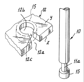
Figure 1 is a partial exploded perspective view of that provided by the state
of the
art;
Figure 2 is a similar partial exploded perspective view of the basic solution
used by
the invention;
Figure 3 is a detailed cross-section through a variant;
Figure 4 is a cross-section through the wall element of the invention
incorporating
that shown in Figure 3.

Figure 2, in which equal or corresponding parts are indicated by the same
reference
numeral used in figure 1 plus 10, shows the essence of the invention. To
enable

the roller pins 10 to replace the core joining the upper and lower base
elements of
the traditional wall element, the pins are made to present at their opposite
ends the
form shown basically in Figure 2, in which the part i 1 a of reduced diameter
is
followed by a head 15 which can have the same diameter as the intermediate
part
of the pin, but must exceed the diameter of the seat 12b which snap-receives
the
smaller- diameter part 11 a of the pin. As indicated by the dashed line, when
the pin
is mounted, the head 15 lies on that side Z of the lower base element 12 (and
of the
upper base element by analogy) opposite the side Y facing the intermediate
part of


CA 02354872 2001-08-08

3
the pin. The heads 15 prevent separation of the upper and lower base elements
of
the wall element, so replacing the function of the connecting core.

Figure 3 shows a variant in which the head 15A is received in a seat
consisting of a
semicylindrical base groove 25 of diameter equal to or greater than the head,
here
indicated by 15A, and with an access 25A having parallel sides spaced apart by
said'
diameter. In this figure, the pin is indicated by 21, the head by 15A, the pin
part of
reduced cross-section by 21 a, the seat (which receives the reduced cross-
section
part 21a) by 22b, the tapered lead-in by 22a, and the lower base element by
22.

Figure 4 shows a partial section through a wall element, indicated overall by
31.
This element uses the solution of Figure 3 for snap- fitting the roller pins,
hence
Figure 4 uses the same reference numerals to indicate equal or corresponding
parts.

The pins 21 are snap-fitted at their opposing ends to the lower 22 and upper
30
base elements as shown in Figure 3. The idle rollers on the pins 21 are
indicated by
32.

As is apparent from Figure 4, the connection between the lower and upper base
elements (which are two separate pieces) is entrusted entirely to the pins 21
carrying the rollers 32. Hence the wall element of the invention dispenses
with that
connection core (between the lower and upper base elements) present in
traditional
wall elements. This absence enables wall elements to be formed having a
substantially smaller overall transverse dimension H (Figure 4).

Representative Drawing
A single figure which represents the drawing illustrating the invention.
Administrative Status

For a clearer understanding of the status of the application/patent presented on this page, the site Disclaimer , as well as the definitions for Patent , Administrative Status , Maintenance Fee  and Payment History  should be consulted.

Administrative Status

Title Date
Forecasted Issue Date 2010-04-06
(22) Filed 2001-08-08
(41) Open to Public Inspection 2002-02-09
Examination Requested 2006-07-10
(45) Issued 2010-04-06
Deemed Expired 2014-08-08

Abandonment History

There is no abandonment history.

Payment History

Fee Type Anniversary Year Due Date Amount Paid Paid Date
Registration of a document - section 124 $100.00 2001-08-08
Application Fee $300.00 2001-08-08
Maintenance Fee - Application - New Act 2 2003-08-08 $100.00 2003-08-01
Maintenance Fee - Application - New Act 3 2004-08-09 $100.00 2004-08-04
Maintenance Fee - Application - New Act 4 2005-08-08 $100.00 2005-07-26
Request for Examination $800.00 2006-07-10
Maintenance Fee - Application - New Act 5 2006-08-08 $200.00 2006-07-26
Maintenance Fee - Application - New Act 6 2007-08-08 $200.00 2007-06-29
Maintenance Fee - Application - New Act 7 2008-08-08 $200.00 2008-07-07
Maintenance Fee - Application - New Act 8 2009-08-10 $200.00 2009-06-19
Registration of a document - section 124 $100.00 2009-12-04
Final Fee $300.00 2010-01-15
Maintenance Fee - Patent - New Act 9 2010-08-09 $200.00 2010-07-16
Maintenance Fee - Patent - New Act 10 2011-08-08 $250.00 2011-07-27
Maintenance Fee - Patent - New Act 11 2012-08-08 $250.00 2012-07-17
Owners on Record

Note: Records showing the ownership history in alphabetical order.

Current Owners on Record
SYSTEM PLAST S.R.L.
Past Owners on Record
MARSETTI, SERGIO
REATTI, RODOLFO
SYSTEM PLAST S.P.A.
Past Owners that do not appear in the "Owners on Record" listing will appear in other documentation within the application.
Documents

To view selected files, please enter reCAPTCHA code :


To view images, click a link in the Document Description column. To download the documents, select one or more checkboxes in the first column and then click the "Download Selected in PDF format (Zip Archive)" or the "Download Selected as Single PDF" button.

List of published and non-published patent-specific documents on the CPD .

If you have any difficulty accessing content, you can call the Client Service Centre at 1-866-997-1936 or send them an e-mail at CIPO Client Service Centre.


Document
Description 
Date
(yyyy-mm-dd) 
Number of pages   Size of Image (KB) 
Description 2001-08-08 3 155
Claims 2001-08-08 1 30
Drawings 2001-08-08 2 42
Representative Drawing 2002-01-14 1 9
Abstract 2001-08-08 1 21
Cover Page 2002-02-01 1 37
Representative Drawing 2010-03-10 1 10
Cover Page 2010-03-10 2 41
Claims 2009-02-17 2 57
Description 2009-02-17 4 189
Assignment 2001-08-08 4 183
Fees 2003-08-01 1 28
Fees 2004-08-04 1 35
Fees 2005-07-26 1 26
Prosecution-Amendment 2006-07-10 1 30
Fees 2006-07-26 1 32
Fees 2007-06-29 1 45
Prosecution-Amendment 2008-08-22 2 55
Fees 2008-07-07 1 45
Prosecution-Amendment 2009-02-17 10 326
Fees 2009-06-19 1 53
Assignment 2009-12-04 9 217
Correspondence 2010-01-15 2 54
Fees 2010-07-16 1 33
Correspondence 2010-08-10 1 47
Fees 2011-07-27 1 32