Note: Descriptions are shown in the official language in which they were submitted.
CA 02355350 2001-06-06
PCT - revised during Phase II
SPR 7/98 PCT
Title: Snaffle bit with two side rings and a shackle
The invention relates to a snaffle bit for a horse with two side rings and one
shackle arranged between said rings, said shackle having at least one joint
on one side and being provided on the other with two side portions, a bore
being provided in the end of each of the side portions that is remote from the
at least one joint, said bore receiving a respective one of the rings in such
a
manner as to allow said rings to move freely.
This type of a snaffle bit for a horse forms the subject of the European
Patent 17 959. In principle, this snaffle bit proved to be very appropriate.
Reference is also made to the snaffle bits cited in this European Patent,
more specifically to those according to US-A-4,005,564; GB-A-7712/ 1914;
GB-A-651913 and DE-C-194 071.
In devising the snaffle bit previously proposed and mentioned herein above,
it proved particularly efficient to design the shackle so as to be even,
smooth
in contour and without edges and to have the transitions between discrete
portions of the shackle made soft. It also proved very advantageous to have
the section of the side portions tapering from the rings inward and this
advantage will be retained. The same is true for the curved design of the
shackle according to which a median line of the shackle that connects the
bores intended to receive the two rings in such a manner as to provide them
with freedom of movement is curved toward the front, toward the roof of the
mouth. With the bit of the type mentioned above, this feature is achieved in
providing the shackle with a joint so that a curved shape can be achieved.
Bits which have a jointed shackle will be designated herein after as "single
joint" snaffle bits, and bits which have a shackle with two joints as "double
joint" snaffle bits. These two embodiments of the snaffle bit for horses of
the
type mentioned herein above have come to be highly appreciated by
horsemen.
The present invention would like to retain the major features of the snaffle
bit of the type mentioned herein above and to develop it in such a way that
it is even more suited and advantageous for a horse and fits better in its
CA 02355350 2001-06-06
2
PCT - revised during Phase II
mouth. With the snaffle bit of the type mentioned herein above it has been
found that the pressure exerted through pulling on the reins not always acts
on the horse's tongue only, but in parts also on the roof of the mouth. But
pressure onto the roof of the mouth is precisely what is not wanted.
This is where the invention comes to effect. It is its object to develop the
snaffle bit of the type mentioned herein above in such a manner that, for a
horse, the fit is improved and that pulling on the reins substantially acts on
the tongue, the pull being initiated by way of the rings. It aims at ensuring
that the bit adjusts in the best possible way to the anatomy of a horse's
mouth.
Starting from the snaffle bit of the type mentioned above, the solution of
this
object is achieved in that the axes of the two bores define a plane that is
inclined at an angle of 45 20 , preferably of 45 10 , to the
articulation
axis of the at least one joint.
Whereas in the previously proposed snaffle bit the articulation axes of the
shackle's joints are lying in the plane that is defined by the bores for the
rings, the angular position of the articulation axes of the joints permitting
but a small deviation from this plane, the invention adopts just the opposite
way. It intentionally arranges the articulation axes of the at least one joint
of
the shackle at an angle of 45 20 to the plane of the bores. As a result,
the bit is provided articulateness in a second plane which is inclined at an
angle of 45 to the plane of the bores. As a result thereof, the bit can
better
adjust in space to a horse's mouth and has higher degrees of freedom of
movement than the snaffle bit of the prior art cited herein above.
Tests have shown that this bit has a considerably improved fit, that it
reinforces the action onto the tongue of the horse and better adjusts to the
anatomy of the horse's mouth.
In a preferred embodiment, the snaffle bit of the invention has one or two
joints. Although three or even more joints may also be provided, the
embodiments of preference have one or two joints.
Moreover, it proved very advantageous to manufacture the bit according to
the invention in the same way as the previously proposed bit mentioned
herein above from an alloy as it has been described in the German Patent
CA 02355350 2001-06-06
3
PCT - revised during Phase II
DE 43 26 550 C 1 that contains a high amount of copper and still has a high
mechanical strength.
In principle, the design of the joints is discretional. It is possible to have
recourse to the embodiments as they have been described in the European
Patent mentioned herein above and in the remaining state of the art. Simple
designs of the joints however proved particularly efficient, namely such in
which the joints are substantially defined by the interlock of two rings. As a
joint, such joints have greater freedom of movement than joints that are
defined by a rigid articulation axis and that allow the two portions joined by
the axis of the joint to merely move in one plane relative to one another. In
that the joints are designed as rings, soft transitions are additionally
achieved. This allows ease of manufacture. Maintenance and cleaning are
easy since the discrete hollow spaces are readily accessible. Furthermore,
additional materials for making the joint move in a smooth way are not
required. Eventually, this design of the joints excludes the risk of jamming
the tongue of the horse and so on.
In a preferred embodiment, the central portion of a bit with two joints has
two paralleled bores for forming the two joints of the shackle. It is however
also absolutely possible to provide the central portion with two bores that
are positioned at right angles to one another.
It proved particularly advantageous to make the central portion of a bit with
two joints the shortest possible. Central portions with a maximum length of
4 cm, more specifically of 3 cm, proved appropriate. In bits with only one
single joint, a short central region resembling a central portion is realized
in
that the unique joint provided there is thicker than the adjacent regions so
that the shortness of less than 4, resp. 3, 2 or below 1 cm needed and
required above is achieved.
In another preferred embodiment, when the bit is normally positioned, the
two axes of the bores for the rings are not parallel to each other on a plane,
they are rather positioned at an angle of less than 90 to the longitudinal
axis of the shackle although they are lying in one plane. Their relative
position forms a V. As a result thereof and depending upon the orientation
of the bit in the horse's mouth, the pressure exerted on the tongue is
reinforced when the reins are pulled. In that the bores are no longer
relatively right-angled, a component of movement is introduced into the bit
CA 02355350 2001-06-06
4
PCT - revised during Phase II
upon pulling on the reins that has positive effects which more specifically
consist in that the tongue is strained in a much better way.
In the embodiment as it has been described above it proved advantageous
when the axes of the bores of a snaffle bit placed in a horse's mouth
intersect underneath the horse's tongue, i.e., below its chin. The desired
positive strain on the tongue is thus preferably exerted. It is however
absolutely possible to arrange the bores in exactly the opposite way. The
arrangement also depends on the angular position of the main articulation
axes of the at least one joint of the shackle. In accordance with these
articulation axes, the bores are made so oblique that the desired positive
strain on the tongue is achieved..
It eventually proved advantageous to thicken the central portion as
compared to the adjacent side portions. The side portions taper from the
rings inward as they do in the prior art bits. In the central region,
increased
thickness is again achieved. Accordingly, the smallest thickness is found
between the central region and the rings. This shape is possible and wanted
for the snaffle bit with one joint as well as for the snaffle bit with two
joints.
In the entire specification of the invention, the terms top, bottom, front and
rear refer to the position of the bit in a horse's mouth when the horse holds
his head in a normal position. Accordingly, the "top" means the region near
the horse's ears, "bottom" refers to the region of the mouth opening, "front"
to the region of the nasal bone and "rear" to the region of the lower jaw.
Further advantages and characteristics of the invention will become
apparent in the remaining claims as well as in the following description of
exemplary embodiments of the invention that are not limiting the scope of
the invention and that are explained in more detail with reference to the
drawing. In the s"drawing
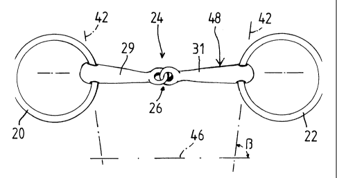
FIG. 1: shows a rear view of a snaffle bit for a horse with two joints,
FIG. 2: shows a view according to Figure 1 for a snaffle bit for a horse
with one single joint,
FIG. 3: shows a view rotated to 90 from the representation in Figure 2
that shows the shackle only, that is, without the rings, the
representation corresponding to a view from the bottom onto the
CA 02355350 2001-06-06
PCT - revised during Phase II
corresponding parts of Figure 2 and
FIG: 4: shows a representation according to Figure 3 for one single side
portion of the bit according to Figure 2.
As can be surveyed from the Figures 1 and 2, the snaffle bit for a horse has
two side rings 20, 22 and a shackle 24 arranged between said two rings 20,
22. In the exemplary embodiment according to Figure 1 it has two joints, in
the exemplary embodiment according to the Figures 2 through 4 it has one
single joint. Accordingly, the exemplary embodiment according to Figure 1
has two joints 26, 28 that are located at either end of a central portion 30
whereas the shackle of the second exemplary embodiment has one single
joint 26.
The shackle 24 has two side portions 29, 31. In the side portions, bores 32
are provided for each receiving a respective one of the rings 20 and 22 in
such a manner as to allow said rings to move freely. The angular position of
these bores 32 will be discussed later. These two bores 32 at the free end
regions of the shackle 24 define a plane that coincides with the plane of the
sheet in the representation according to the Figures 1 and 2. In the
illustration according to Figure 3, this plane is normal to the plane of the
paper.
In the exemplary embodiments illustrated in the Figures, the joints 26, 28
are each designed as eyes that interlock with play, said eyes being provided
at the inner end regions of the side portions 29, 31 or, with the bit that has
two joints, at the central portion 30. This specific design of the joints 26,
28
provides the thus connected parts with a limited three-dimensional range of
movement. The center of the allowable range of the joint is understood to be
the articulation axis. It substantially corresponds to the spatial position of
a
centrical axis through an eye. The articulation axis is indicated in Figure 3
by a dot-dash line at 34. The specific design of the joint that consists of
two
interlocking eyes provides a second articulation axis 36 that is arranged at
right angles thereto. It is indicated in Figure 3 by a dot-dash line 36. Both
axes are inclined at an angle of 45 to the plane of the bores 32 and
accordingly to the plane of the paper in Figure 3.
For a better representation, in the embodiment according to the Figures 2
through 4, the free inner section of the hole of each eye is relatively large
as
CA 02355350 2001-06-06
6
PCT - revised during Phase II
compared to the section of the ring that constitutes the eye, so that the
joints 26 also have large play in longitudinal direction of the side portions
29, 31 for example. The representation is thus easier to understand. In
practical realization however, the clear spaces are smaller. The section of
the
ring fills at least half of the hole of the eye, preferably more, as may be
surveyed from Figure 1. In a preferred embodiment, the ring section is larger
than 70% of the free section of the eye's hole, 80% are also possible, and
90% as well.
In the embodiment according to Figure 1, the central portion 30 has two
paralleled joint bores 38, 40. In another embodiment, these joint bores may
also be relatively right-angled. In the representation according to Figure 1,
these two bores are spaced from each other by a relatively short distance, of
between 2 and 3 cm for example. As a result thereof, the overall central
portion 30 is quite short, it is a maximum of 4 cm in length and preferably a
maximum of 3 cm in length. It is markedly thicker than the adjacent region
of the side portions so that the already mentioned larger cross section in the
center of the shackle 24 is obtained. In both exemplary embodiments, the
cross section of the shackle 24 diminishes symmetrically to both sides and
thickens again in the region of the bore 32 to attain a thickness which is
comparable to the thickness in the center.
In Figure 1, the central portion 30 has the shape of an olive. It may also
have another design and for example be a disk at which sides two eyes
axially protrude, a roll, of a rather spherical form, and so on.
As can more particularly be surveyed from the Figures 3 and 4, the side
portions are curved. This is particularly obvious in Figure 4 that shows that
the overall central portion 30 lies on a slight arch. The shape of this arch
is
chosen to be such that the center of the shackle 24 in the horse's mouth
extends more downward than the other parts of the shackle.
As can be particularly surveyed from Figure 2, the two bores 32 are each
positioned not at right angles to the longitudinal direction of the side
portions, but at an angle beta which is not equal to 90 , more specifically at
an angle of beta = 60 to 85 . This can be seen from Figure 2. Figure 2 shows
that the bores 32 penetrate the free outer ends of the side portions at a
slant
angle, the axes of the bores 32 are indicated by a dot-dash line at 42. 44 is
a
straight dot-dash connecting line through the free end regions of the side
portions. The dot-dash straight line 46 is parallel to the straight line 44
and
CA 02355350 2001-06-06
7
PCT - revised during Phase II
was drawn to better illustrate the angles of intersection with the axes 42.
Figure 2 shows that the axes 42 are inclined at an angle beta of
approximately 82 to the straight line 46. The two axes 42 thereby intersect
at the rear. It can be seen that, irrespective of the concrete embodiment of
the joint, the arrangement exhibits 2-fold symmetry to a median line.
Unlike the existing state of the art snaffle bits for a horse, the snaffle bit
according to the invention has one side that should customarily lie in front.
It is indicated by the arrow 48 in the Figures 1 and 2. In practical
embodiments of the bits, the corresponding areas of at least one portion, of
a side portion for example, are labeled accordingly, with "front" for example.
Depending on its construction, the bit of the previously proposed type only
adopts a favorable position in the cavity of the horse's mouth when the reins
are either eased or taken. The improvement is effected by the fact that the
novel bit evenly adapts to the spatial conditions in the cavity of the horse's
mouth whether the reins are eased or taken.
Preferably the central portion has two bores, the median lines of which are
less than 2.5 cm, preferably less than 2 cm apart.
Preferably the at least one joint and all the other joints are designed as
eyes
that interlock with play and are provided at the end regions of the side
portions or of the central portions.