Note: Descriptions are shown in the official language in which they were submitted.
CA 02355379 2006-10-20
COMPACT MATERIAL PUSHER WITH UNIVERSAL DESIGN
AND METHOD OF MANUFACTURE
This invention relates generally to an improved material pusher for use
with agricultural equipment, and more particularly to a design and
method of manufacture of a compact material pusher in order to improve the
manufacturability of the material pusher.
BACKGROUND AND SUMMARY OF THE INVENTION
The present invention is an improved snow or material pusher for use
with agricultural and larger home and garden tractors on generally flat areas
such as driveways, feed lots, and loading and parking areas.
A "pusher" differs from a typical snow plow blade or bucket as might
generally be found on such implements. Pushers, as described, for
example in US-A-5,724,755 to Weagley (issued March 3, 1998) or the folding
Material Plow of US-A-6,112,438, to Weagley et al. (issued September 9, 2000),
both assigned to Pro-Tech Welding and Fabrication, Inc. include sides
extending
forward from the mold board to assure material being pushed (e.g., material,
water, debris, sludge, etc.) remains in front of the pusher, and is not
directed
to the side as with conventional plows. Whereas the larger material pushers
were designed for use with loaders and other heavy-duty equipment for
clearing parking lots, runways and roads, there is a need for a smaller,
lighter-weight version that may be used by agricultural and lawn/garden
tractors having front or rear lifting capability (e.g., buckets) - not only
for
snow removal, but for clearing of debris, including animal waste, etc.
Heretofore, a number of patents and publications have disclosed
plow configurations, the relevant portions of which may be briefly summarized
as follows:
US-A-5,724,755 to Weagley, issued March 3, 1998, discloses a snow
pusher having a transverse blade, side plates, wear shoes and horizontal
posts for attaching the pusher to a bucket loader.
US-A-6,112,438, to Weagley et al., issued September 9, 2000, is directed
to a foldable version of the snow pusher.
1
CA 02355379 2001-08-17
Atty. Dkt. No. MJG-1
In accordance with the present invention, there is provided a material pusher
including: an upstanding transverse blade with a front surface and a rear
surface,
said rear surface of said blade being stiffened using at least two
longitudinal
channels extending substantially the length of said blade and in parallel with
one
another, wherein one of said longitudinal channels is attached to the rear
surface of
said blade in a position so as to make an outer surface of the channel
substantially
perpendicular with the ground surface upon which the material pusher will
travel and
where the one channel further provides at least one surface for mounting of an
attachment mechanism; a reversible rubber edge removably fastened to a lower
io edge of said blade at a position adjacent the ground surface; vertical side
plates
extending forward from each of a pair of opposing ends of said blade; and a
wear
shoe removably mounted on each of said side plates for sliding contact with
the
ground surface.
In accordance with another aspect of the present invention, there is provided
is a method of manufacturing a material pusher, comprising the steps of:
bending
metal plate into an arc to produce an upstanding transverse blade with a front
surface and a rear surface; welding, to said rear surface of said blade, at
least a top
and a main longitudinal channel extending substantially the length of said
blade and
in parallel with one another to stiffen said blade, wherein said main
longitudinal
20 channel is attached to the rear surface of said blade in a position so as
to make an
outer surface of said main channel substantially perpendicular with the ground
surface upon which the material pusher will travel and where said main channel
further provides at least one surface for mounting of an attachment mechanism;
attaching, to each of a pair of opposing ends of said blade, vertical side
plates
25 extending forward from the blade; attaching a reversible rubber edge to a
lower
edge of said blade at a position adjacent the ground surface; and removably
mounting wear shoes on each of said side plates for sliding contact with the
ground
surface.
One aspect of the invention is based on the discovery that a pusher suitable
30 for use with a broad range of agricultural tractors and other equipment may
be
partially mass-produced and then completed, with appropriate attachment
2
CA 02355379 2001-08-17
Atty. Dkt. No. MJG-1
mechanisms, in response to customer orders or inventory requirements.
Furthermore, the design of such units results in a reduction in weight
required to
make the pushers usable with smaller tractors such as those found in
agricultural
and home/garden situations. This discovery of a design employing a main
longitudinal channel that serves for stiffening the pusher blade and as a
mounting
attachment bearing surface avoids problems that arise in providing a variety
of
mounting attachments.
The techniques described above are advantageous because they provide a
simple means of enabling the efficient production of compact pushers with a
variety
io of attachment requirements, as compared to other approaches that require a
custom design for each attachment mechanism. The techniques make it
unnecessary to have a large inventory of pushers for each type of tractor that
could
use the pusher. Furthermore, the technique can be adapted to any of a number
of
plow or implement designs. As a result of the invention, it is possible to pre-
is fabricate components of the final pusher product and to simply tailor the
attachment
mechanism to the customer requirements, and mount the attachment mechanism to
the blade assembly prior to shipping to the customer.
BRIEF DESCRIPTION OF THE DRAWINGS
Figure 1 is a perspective illustration of an embodiment of the present
20 invention;
Figure 2 is a side orthogonal view of the present invention with alternative
embodiments depicted;
Figures 3 and 4 are assembly views of components for the alternative
attachment mechanism that form part of the present invention;
25 Figure 5 is a perspective illustration of an alternative embodiment of the
present invention; and
Figure 6 is flow chart illustrating the various steps of a bifurcated
manufacturing process in accordance with an aspect of the present invention.
The present invention will be described in connection with a preferred
3o embodiment, however, it will be understood that there is no intent to limit
the
3
CA 02355379 2001-08-17
Atty. Dkt. No. MJG-1
invention to the embodiment described. On the contrary, the intent is to cover
all
alternatives, modifications, and equivalents as may be included within the
spirit and
scope of the invention as defined by the appended claims.
DESCRIPTION OF THE PREFERRED EMBODIMENT
For a general understanding of the present invention, reference is made to
the drawings. In the drawings, like reference numerals have been used
throughout
to designate identical elements. In describing the present invention, the
following
term(s) have been used in the description. A "ground surface" refers to any
surface
such as a roadway, driveway, parking lot, runway, feed lot or the like where a
pusher
io is to be used. Such ground surfaces are generally flat areas that do not
have
significant bumps or barriers extending upward and above the surrounding
region.
Similarly, "rubber" is intended as a convenient term to include the entire
range of
rubbers or elastomeric materials, particularly those suitable for the use as a
flexible
yet resilient edge as described herein.
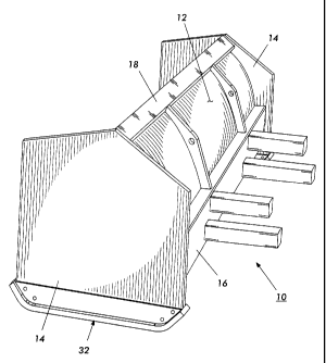
Referring now to the figures, the pusher 10 includes an upstanding steel
blade 12 constructed of 0.125 inch thick steel plate, and a vertical side
plate 14
made of 0.125 inch steel plate at each end of the blade 10 and extending
generally
in a forward direction from the blade. The rear or back side of the blade 10
includes
at least two horizontal reinforcing channels 16 and 18 welded across the
longitudinal
width of the blade 12. Longitudinal channels 16 and 18 are both U or C-shaped
rectangular channel, where the upper channel 18 has a channel width of
approximately 3 inches, height of approximately 1.41 inches and a wall
thickness of
approximately 0.170 inches and the lower or main channel has a channel width
of
approximately 8 inches, height of approximately 2.26 inches and a wall
thickness of
approximately 0.220 inches. The reinforcing channel members 16 and 18 are
welded along their entire lengths to the blade 12. Welded straight channels
are
believed to be inherently stronger and not prone to failure by buckling, as
compared
to vertical curved ribs cut from steel plate.
Furthermore, as depicted in Figure 2, the rear surface of main channel 16,
surface 17, is positioned so that it is generally perpendicular to the ground
surface
4
CA 02355379 2001-08-17
Atty. Dkt. No. MJG-1
on which the blade will ride. Placement of the main channel in such a position
allows the channel to be used as the structural component to which any of a
number
of mounting attachments may be attached.
Pusher 10 may also include a backing flat stock member (not shown) behind
the bottom edge of the blade 12, where the backing member would also extend
the
width of the blade to provide support to the lower blade edge. The backing
member
may also be stiffened by gussets (not shown) spaced along the width of the
blade.
Referring also to Figure 2, there is shown a side view of the pusher. In
Figure 2, a
resilient rubber edge 22 is mounted along the bottom of the blade 12,
extending
io approximately two inches below the bottom edge of the blade. The rubber
edge 22
is at least 1.0 inch thick and approximately 6.0 inches in height. Rubber edge
22 is
made from a rubber or similar eiastomeric material, preferably having a
durometer
of approximately 6.8, and includes bolt holes for removably mounting to edge
the
blade 12 using a face plate 26 and threaded bolts and nuts 28. Mounting of the
rubber edge 16 is adjustable and reversible to accommodate for wear.
The vertical side plate 14 extends in a generally forward direction from each
end of the blade 12. Each side plate includes a removable wear shoe 32 on its
bottom for sliding contact with the ground surface. The wear shoes 32 each
include
a bottom runner 33 and a vertical web 34. The runners 33 are made of A514;T-1
2o high carbon alloy steel, approximately 0.75 inches thick and 3.0 inches
wide, with
45-degree. ramp surfaces 35 at the front and back to permit easy riding over
surface
irregularities and the like. The wear shoe 32, by means of bolt through-holes
in their
vertical webs 34, are removably fastened to their respective vertical side
plates 14
by bolts (not shown). When the wear shoes 32 are affixed to the side plates,
there
is a clearance of about two inches between the ground surface and the blade
bottom. The rubber edge 22 extends to the ground surface and acts as a
"squeegee" over the ground surface, but does not bear the weight of the
pusher.
Rubber edge 22 is preferably flexible enough to glide over ground surface
irregularities without gouging asphalt, concrete, or tar-gravel surfaces. It
also rides
3o easily over grates, manhole covers, and other such potential hazards,
permitting
higher speed and damage-free material removal.
5
CA 02355379 2001-08-17
Atty. Dkt. No. MJG-1
Referring next to Figure 2 in conjunction with Figures 3, 4 and 6, the method
of manufacturing a compact pusher in accordance with the present invention
will be
described in detail. In particular, the blade assembly is initiated at step
100 by
bending the blade stock into an arc-shaped blade. Subsequently, at step 102,
the
main horizontal channel is welded to the blade along its length so as to
provide a
rigidized blade. In one embodiment, a 0.025 inch thick flat plate may also be
welded along the bottom of the steel blade to provide a reinforced mounting
support
for the rubber edge. Next, at step 104, the top horizontal channel is welded
to the
blade, again along its entire length to stiffen the upper portion of the
blade. At step
io 106, the side plates are fabricated and attached to the main blade assembly
by
welding. Having completed steps 100 - 106, the blade is in a semi-completed
condition, where the blade assembly 36 (including at least blade, side plates
and
longitudinal channels) may then be stored in inventory. It is also possible,
as
reflected in steps 110 and 112 respectively, to attach the removable wear
shoes to
is the bottoms of the side plates and to provide and mount the rubber edge to
the
blade bottom at this point if the assembly has been primed or painted (not
shown).
As depicted through step 112 of Figure 6, and in Figure 2, the blade
assembly is complete, except that the particular mounting assembly to be used
for
the pusher is not yet installed. As further represented in Figures 3 and 4,
and by
20 step 116 of Figure 6, assembly of the pusher may be completed after receipt
of a
customer order (step 114), where the appropriate attachment mechanism is
determined based upon the customer requirements and the unit is then completed
by mounting the attachment mechanism 38 to the rear of the blade assembly 36
and
shipped (to a customer or a distributor).
25 Referring specifically to Figure 3, a "universal" flat plate mounting
system is
employed to allow for easy customization and pre-fabrication of an original
equipment manufacturer (OEM) coupler that will adapt to numerous tractors
having
bucket attachments. The universal mount 38 depicted in Figure 3 includes a
flat
plate 40 of 0.3125 inch thick steel having a width of at least approximately
24
30 inches and a height of approximately 18 inches. The plate has at least one
gusset
42 welded or attached to an edge or back side thereof. Gusset 42 is preferably
6
CA 02355379 2001-08-17
Atty. Dkt. No. MJG-1
designed so as to fit within the region between longitudinal channels 16 and
18,
linking the two channels and providing support for the rear surface of the
blade. It
will be appreciated that plate 40 and gusset(s) 42 may be prefabricated and
assembled.
Subsequently, once the configuration of a customer's tractor is known,
mounting bosses 44, of a pivot/pin type and a hook or similar protrusion 46,
may be
welded or otherwise attached to plate 40 at the proper locations for use with
a
particular tractor make/model. When the attachment mechanism 38 is completed,
it
may then be assembled or mounted to the blade assembly by weiding or otherwise
io affixing the mechanism to the blade assembly. It will be appreciated that
welding
may be a preferred process for completing the fabrication of the assembly,
however,
various alternative assembly methods exist, including rivets and high-strength
bolts
that may prove suitable for smaller size blade assemblies. Referring briefly
to
Figure 5, there is shown an exemplary illustration of the assembly of a
universal
attachment mechanism 38, as depicted in Figure 3, to the rear of a blade
assembly
10.
Referring next to Figure 4, depicted therein are the components of an
alternative attachment mechanism 38, including a pair of horizontal posts 50.
In a
preferred embodiment attachment mechanism 38 would include at least two pairs
of
such posts, providing an upper horizontal row of posts 52, and a lower
horizontal
row of posts 54, extending out from the main longitudinal channel 16 on the
back of
the blade assembly. The parallel upper and lower rows of posts form a
horizontal
receptacle or slot 56 therebetween for receiving a bucket (not shown) of a
tractor.
The bucket is movable into and out of the slot 56 to, respectively, engage the
pusher 10 for operation, and to disengage the pusher.
The horizontal posts 52 and 54 are rectangular in cross-section (e.g., 3x3
inches) as depicted in Figure 1, but may also be formed in the nature of arms
or
other rearwardly extending features defining a horizontal slot therebetween.
Such
an attachment mechanism is well-known for use on snow pushers. In general, the
upper posts 52 are of slightly shorter in length than the lower posts 54 so as
to
facilitate the placement and engagement of the lower lip of a tractor bucket.
As
7
CA 02355379 2001-08-17
Atty. Dkt. No. MJG-1
illustrated in Figures 1 and 2, the orientation of channel 16, so that its
rear-facing
surface 17 is oriented vertically, allows for the bucket attachment mechanism
to be
directly welded thereto without special cutting of the ends of tubes 52 and
54.
As further depicted in Figure 4, the attachment mechanism 38 includes at
least one reinforcing gusset 59 spanning between the main and top longitudinal
channels. It will be appreciated that while these individual items may be
fabricated
as individual components that subsequently attached to the blade assembly,
they
may also be fabricated as an assembly by the addition of a temporary coupling
or
fixturing jig 58 that will allow for ease of assembly when a blade assembly is
to be
io fabricated with a bucket-type attachment mechanism as depicted in Figures 1
and 4.
In recapitulation, the present invention is directed to a pusher apparatus for
moving materials and a method for manufacturing such pushers on a large scale
using a bifurcated manufacturing design and process that allows for easy
customization of the pushers for use with a plurality of agricultural tractor
is configurations. The bifurcated process includes pre-fabrication of a blade
assembly
with at least a blade, channel supports and vertical side walls, and a
subsequent
process for completing the assembly by mounting one of at least two
alternative
attachment mechanisms to the rear of the blade assembly.
. It is, therefore, apparent that there has been provided, in accordance with
the
20 present invention, an apparatus and efficient method of manufacturing a
compact
pusher for use with agricultural tractors. While this invention has been
described in
conjunction with preferred embodiments thereof, it is evident that many
alternatives,
modifications, and variations will be apparent to those skilled in the art.
Accordingly,
it is intended to embrace all such alternatives, modifications and variations
that fall
25 within the spirit and broad scope of the appended claims.
8
f