Language selection

Search

Patent 2355422 Summary

Third-party information liability

Some of the information on this Web page has been provided by external sources. The Government of Canada is not responsible for the accuracy, reliability or currency of the information supplied by external sources. Users wishing to rely upon this information should consult directly with the source of the information. Content provided by external sources is not subject to official languages, privacy and accessibility requirements.

Claims and Abstract availability

Any discrepancies in the text and image of the Claims and Abstract are due to differing posting times. Text of the Claims and Abstract are posted:

  • At the time the application is open to public inspection;
  • At the time of issue of the patent (grant).
(12) Patent Application: (11) CA 2355422
(54) English Title: METHOD OF POSITIONING A FLAVOUR ENHANCING BODY WITHIN A BEVERAGE BOTTLE AND A BEVERAGE BOTTLE CONTAINING SUCH A FLAVOUR ENHANCING BODY
(54) French Title: METHODE DE POSITIONNEMENT D'UN CORPS RENFORCATEUR D'AROME DANS UNE BOUTEILLE DE BOISSON ET BOUTEILLE DE BOISSON CONTENANT UN TEL CORPS RENFORCATEUR D'AROME
Status: Deemed Abandoned and Beyond the Period of Reinstatement - Pending Response to Notice of Disregarded Communication
Bibliographic Data
(51) International Patent Classification (IPC):
  • B65D 01/04 (2006.01)
  • B65D 01/06 (2006.01)
  • C03B 23/20 (2006.01)
  • C12H 01/22 (2006.01)
(72) Inventors :
  • NANUAN, RAJ (Canada)
(73) Owners :
  • RAJ NANUAN
(71) Applicants :
  • RAJ NANUAN (Canada)
(74) Agent: THOMPSON LAMBERT LLP
(74) Associate agent:
(45) Issued:
(22) Filed Date: 2001-08-17
(41) Open to Public Inspection: 2003-02-17
Availability of licence: N/A
Dedicated to the Public: N/A
(25) Language of filing: English

Patent Cooperation Treaty (PCT): No

(30) Application Priority Data: None

Abstracts

English Abstract


A method of positioning a flavour enhancing body within
a beverage bottle. A first step involves providing two
discrete bodies which, when joined, will form a beverage bottle
having an access neck with a liquid channel communicating with
a liquid retention cavity. A second step involves inserting
a flavour enhancing body into one of the discrete bodies. The
flavour enhancing body is larger than the liquid channel, such
that it can not be removed through the access neck. A third
step involves joining the two discrete bodies to form the
beverage bottle with the flavour enhancing body permanently
trapped within the liquid retention cavity.


Claims

Note: Claims are shown in the official language in which they were submitted.

8
THE EMBODIMENTS OF THE INVENTION IN WHICH AN EXCLUSIVE PROPERTY
OR PRIVILEGE IS CLAIMED ARE DEFINED AS FOLLOWS:
1. A method of positioning a flavour enhancing body within a
beverage bottle, comprising the steps of:
providing two discrete bodies which, when joined, will
form a beverage bottle having an access neck with a liquid
channel communicating with a liquid retention cavity;
inserting a flavour enhancing body into one of the
discrete bodies, the flavour enhancing body being larger than
the liquid channel, such that it can not be removed through the
access neck; and
joining the two discrete bodies to form the beverage
bottle with the flavour enhancing body permanently trapped
within the liquid retention cavity.
2. The method as defined in Claim 1, the flavour enhancing
body being substantially saturated with water in order to
protect the flavour enhancing body from damage due to heat as
the two discrete bodies are joined to form the beverage bottle.
3. The method as defined in Claim 1, the flavour enhancing
body being frozen in order to protect the flavour enhancing
body from damage due to heat as the two discrete bodies are
joined to form the beverage bottle.
4. The method as defined in Claim 1, the flavour enhancing
body being a piece of fruit.
5. The method as defined in Claim 1, the flavour enhancing
body being a piece of wood with known properties for aging
beverages.
6. The method as defined in Claim 5, the wood being encased
in a filtering membrane.
7. The method as defined in Claim 1, the flavour enhancing

9
body being in the shape of a sphere.
8. The method as defined in Claim 1, the flavour enhancing
body being a filtration element.
9. The method as defined in Claim 8, the filtration element
being in the shape of one of a cone and a funnel with a
relatively narrow egress extending into the liquid channel of
the access neck.
10. The method as defined in Claim 1, the flavour enhancing
body bearing indicia identifying the manufacturer.
11. The method as defined in Claim 1, the flavour enhancing
body bearing indicia identifying the date of manufacture.
12. The method as defined in Claim 1, the discrete bodies
being made of glass.
13. The method as defined in Claim l, the flavour enhancing
body being enclosed in a removable heat resistant sack in order
to protect the flavour enhancing body from damage due to heat
as the two discrete bodies are joined to form the beverage
bottle.

10
14. A method of positioning a flavour enhancing body within
a beverage bottle, comprising the steps of:
providing two discrete glass bodies which, when joined,
will form a beverage bottle having an access neck with a liquid
channel communicating with a liquid retention cavity;
inserting a frozen flavour enhancing body in the form of
a piece of fruit into one of the discrete bodies, the piece of
fruit being larger than the liquid channel, such that it can
not be removed through the access neck; and
applying heat to join the two discrete glass bodies to
form the beverage bottle with the piece of fruit permanently
trapped within the liquid retention cavity.

11
15. A method of positioning a flavour enhancing body within
a beverage bottle, comprising the steps of:
providing two discrete glass bodies which, when joined,
will form a beverage bottle having an access neck with a liquid
channel communicating with a liquid retention cavity;
inserting a frozen flavour enhancing body in the form of
at least one piece of wood with known beverage aging properties
into one of the discrete bodies, the at least one piece of wood
being larger than the liquid channel, such that it can not be
removed through the access neck; and
applying heat to join the two discrete glass bodies to
form the beverage bottle with the at least one piece of wood
permanently trapped within the liquid retention cavity.
16. The method as defined in Claim 12, the flavour enhancing
body being in the shape of a sphere.
17. The method as defined in Claim 12, the flavour enhancing
body being in the shape of an animate object.
18. The method as defined in Claim 12, the flavour enhancing
body bearing indicia identifying the manufacturer.
19. The method as defined in Claim 12, the flavour enhancing
body bearing indicia identifying the date of manufacture.

12
20. A method of positioning a flavour enhancing body within
a beverage bottle, comprising the steps of:
providing two discrete glass bodies which, when joined,
will form a beverage bottle having an access neck with a liquid
channel communicating with a liquid retention cavity;
inserting a frozen flavour enhancing body in the form of
a filtration element into one of the discrete bodies, the
filtration element being larger than the liquid channel, such
that it can not be removed through the access neck; and
applying heat to join the two discrete glass bodies to
form the beverage bottle with the filtration element
permanently trapped within the liquid retention cavity.
21. The method as defined in Claim 17, the filtration element
being one of a cone and a funnel, with a relatively narrow
egress extending into the liquid channel of the access neck.

13
22. A beverage bottle containing a flavour enhancing body,
comprising:
a beverage bottle having an access neck with a liquid
channel communicating with a liquid retention cavity; and
a flavour enhancing body positioned in the liquid
retention cavity, the flavour enhancing body being larger than
the liquid channel, such that it can not be removed through the
access neck and is permanently trapped within the liquid
retention cavity.
23. The beverage bottle as defined in Claim 19, wherein the
flavour enhancing body is a piece of fruit.
24. The beverage bottle as defined in Claim 19, wherein the
flavour enhancing body is a piece of wood.
25. The beverage bottle as defined in Claim 19, wherein the
flavour enhancing body is in the shape of a sphere.
26. The beverage bottle as defined in Claim 19, wherein the
flavour enhancing body is a filtration element.
27. The beverage bottle as defined in Claim 23, wherein the
filtration element is one of a cone and a funnel.
28. The beverage bottle as defined in Claim 19, wherein the
flavour enhancing body bears indicia identifying the
manufacturer.
29. The beverage bottle as defined in Claim 19, wherein the
flavour enhancing body bears indicia identifying the date of
manufacture.
30. The beverage bottle as defined in Claim 19, wherein the
discrete bodies are made of glass.

14
31. A beverage bottle containing a flavour enhancing body,
comprising:
a glass beverage bottle having an access neck with a
liquid channel communicating with a liquid retention cavity;
and
a flavour enhancing body in the form of a piece of fruit
positioned within the liquid retention cavity, the piece of
fruit being larger than the liquid channel, such that it can
not be removed through the access neck and is permanently
trapped within the liquid retention cavity.

15
32. A beverage bottle containing a flavour enhancing body,
comprising:
a glass beverage bottle having an access neck with a
liquid channel communicating with a liquid retention cavity;
a flavour enhancing body in the form of at least one piece
of wood with known beverage aging properties positioned in the
liquid retention cavity, the at least one piece of wood being
larger than the liquid channel, such that it can not be removed
through the access neck and is permanently trapped within the
liquid retention cavity.
33. The beverage bottle as defined in Claim 29, wherein the
flavour enhancing body is in the shape of a sphere.
34. The beverage bottle as defined in Claim 29, wherein the
flavour enhancing body is in the shape of an animate object.
35. The beverage bottle as defined in Claim 29, wherein the
flavour enhancing body bears indicia identifying the
manufacturer.
36. The beverage bottle as defined in Claim 29, wherein the
flavour enhancing body bears indicia identifying the date of
manufacture.

16
37. A beverage bottle containing a flavour enhancing body,
comprising:
a glass beverage bottle having an access neck with a
liquid channel communicating with a liquid retention cavity;
a flavour enhancing body in the form of a filtration
element positioned in the liquid retention cavity, the
filtration element being larger than the liquid channel, such
that it can not be removed through the access neck and is
permanently trapped within the liquid retention cavity.
38. The beverage bottle as defined in Claim 34, wherein the
filtration element is one of a cone and a funnel, with a
relatively narrow egress extending into the liquid channel of
the access neck.

Description

Note: Descriptions are shown in the official language in which they were submitted.


CA 02355422 2001-08-17
1
TITLE OF THE INVENTION:
Method of Positioning A Flavour Enhancing Body Within A
Beverage Bottle and A Beverage Bottle Containing Such a Flavour
Enhancing Body.
G
FIELD OF THE INVENTION
The present invention relates to a method of positioning
a flavour enhancing body within a beverage bottle and a
beverage bottle contain:i:ng such a flavour enhancing body.
1C
BACKGROUND OF THE INVENTION
U.S. Patents 3,942,423 (Herzfeld 1976) and 4,173,656
(Duggins 1979) describe the use of flavour enhancing bodies
positioned within a beverage bottle. The Herzfeld reference
1~ uses an elongated wooden rod in a bottle to age wine. The
Duggins reference uses wood particles confined in filter paper
to age liquor.
SUMMARY OF THE INVENTIOIf
2C The present invention relates to a novel and inventive
approach to positioning flavour enhancing bodies in beverage
bottles.
According to one a~;pect of the present invention there is
2~ provided a method of positioning a flavour enhancing body
within a beverage bott:Le. A ffirst step involves providing two
discrete bodies which, when joined, will form a beverage bottle
having an access neck with a liquid channel communicating with
a liquid retention cavity. A second step involves inserting
3C a flavour enhancing body into one of the discrete bodies. The
flavour enhancing body i.~~ larger than the liquid channel, such
that it can not be removed through the access neck. A third
step involves joining the two discrete bodies to form the
beverage bottle with the flavour enhancing body permanently
3~~ trapped within the liquid retention cavity.
According to another aspect of the present invention there

CA 02355422 2001-08-17
2
is provided a beverage bottle containing a flavour enhancing
body. The beverage bottle has an access neck with a liquid
channel communicating urith a liquid retention cavity. The
flavour enhancing body is positioned in the liquid retention
cavity. The flavour enhancing body is larger than the liquid
channel. It can not be removed through the access neck and is
permanently trapped within the liquid retention cavity.
As the use of flavour enhancing bodies in beverage bottles
becomes more popular, the above method and product are viewed
as setting forth a more functional and aesthetically appealing
approach. The consumer' does not have to worry about the
flavour enhancing body in his beverage bottle, coming out as
the beverage is poured.
In some beverage bottle manufacturing processes, for
example the forming of glass bottles, considerable heat is
generated. Even more beneficial results may, therefore, be
obtained when the flavour enhancing body is frozen in order to
2C protect the flavour enhancing body from damage due to heat as
the two discrete bodies are j oined to form the beverage bottle .
The selection of flavour enhancing body will depend upon
the type of beverage being bottled. With beverages that do not
need to be "aged", the flavour enhancing body will likely be
a piece of fruit. With beverages that do need to be "aged",
the flavour enhancing body is more likely to be a piece of
wood.
3C The shape of the flavour enhancing body can vary. For
example, with Tequila it might be a symbol such as a cactus.
It is considered that tree most common shape for the flavour
enhancing body will be that of a sphere.
3c It is considered i~o be highly desirable that whenever
possible indicia be marked on the flavour enhancing body. With
wood used to age beverages, the wood can bear as indicia the

CA 02355422 2001-08-17
3
manufacturer's Trade Mark, the date of manufacture or both.
Of course the date of manufacture is particularly relevant
where the quality and pe=rceived value of the beverage increases
with age.
For beverages that: tend to have sediment, the flavour
enhancing body will likely be a filtration element that will
capture the sediment. In order to perform most effectively it
is preferred that the filtration element be formed in the shape
1U of either a cone or a funnel, with a relatively narrow egress
extending into the liquid channel of the access neck.
BRIEF DESCRIPTION OF TH:E DRAWINGS
These and other features of the invention will become more
15 apparent from the following description in which reference is
made to the appended drawings, the drawings are for the purpose
of illustration only a.nd are not intended to in any way limit
the scope of the invention to the particular embodiment or
embodiments shown, wherein:
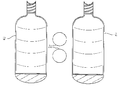
2() FIGURE 1 is a side elevation view of two discrete bodies
used to form a beverage bottle and flavour enhancing bodies in
accordance with the teachings of a .first step of the preferred
method.
FIGURE 2 is a side elevation view of the two discrete
25 bodies used to form a beverage bottle and flavour enhancing
bodies in accordance with the teachings of the second step of
the preferred method.
FIGURE 3 is a side elevation view of a beverage bottle
containing flavour enhancing bodies in accordance with the
30 teachings of the present invention.
FIGURE 4 is a perspective view of the beverage bottle
containing flavour enhancing bodies illustrated in FIGURE 3,
in the process of being poured.
FIGURE 5 is a perspective view of a beverage bottle
35 containing a flavour enhancing body in the form of a piece of
fruit.
FIGURE 6 is a perspective view of a beverage bottle

CA 02355422 2001-08-17
4
containing a flavour enhancing body in the form of a cactus
shaped piece of wood.
FIGURE 7 is a perspective view of a beverage bottle
containing a flavour enhancing body in the form of a filtration
funnel in the process o:~ being poured.
FIGURE 8 is a side elevation view of a beverage bottle
with a removable heat r.=_sistant sack.
FIGURE 9 is a side elevation view of the beverage bottle
illustrated in FIGURE 8, in the process of removing the
removable heat resistant sack.
DETAINED DESCRIPTION OF THE PREFERRED EMBODIMENT
The preferred method of positioning a flavour enhancing
body within a beverage bottle will now be described with
reference to FIGURES 1 through 9.
Referring to FIGURE. 1, a first step involves providing two
discrete bodies 12 which, when joined, will form a beverage
bottle 14 as illustrated in FIGURE 3. In the illustrated
example discrete bodies 12 are made for glass, but they could
be made from plastic or other suitable materials. There is
also illustrated flavour enhancing bodies 22. It is preferred,
but not essential, than the materials be transparent so the
flavour enhancing bodies 22 can be seen. Referring to FIGURE
3, beverage bottle 14 has an access neck 16 with a liquid
channel 18 that communicates with a liquid retention cavity 20.
A second step involves inserting flavour enhancing bodies
22 into one of discrete bodies 12. The form of flavour
enhancing bodies 22 that are illustrated are pieces of wood
with known beverage aging properties . Those pieces of wood are
in the form of spheres. As will hereinafter be described,
there are other types of flavour enhancing bodies 22 , other
than wood, that can be used. As well, the shape of the flavour
3~~ enhancing body 22 need riot be in the form of a sphere. What
is essential, however, :is that the flavour enhancing bodies 22
are larger than liquid channel 18. This is selection is

CA 02355422 2001-08-17
deliberate so that flavour enhancing bodies 22 can not be
removed through access neck 16 when discrete bodies 12 are
joined. It is preferred that flavour enhancing bodies 22 be
protected from heat damage when discrete bodies 12 are joined
to form beverage bottle 14. There are several ways in which
this can be done. For example, flavour enhancing bodies 22 are
pieces of wood the wood can be saturated with water, frozen,
enclosed in a removable heat resistant sack or a combination
of the above. Out of an abundance of caution it is preferred
1C~ that flavour enhancing bodies 22 be both frozen or saturated
with water and then placed in a removable heat resistant sack,
as is illustrated in FIGURES 8 and 9 and hereinafter be further
described.
1~~ A third step involves applying heat to join two discrete
bodies 12 to form beverage bottle 14 with the flavour enhancing
bodies 22, in this case pieces of wood, permanently trapped
within liquid retention cavity 20.
20 It is preferred that flavour enhancing bodies 22 bear a
first indicia 24 identifying the manufacturer and second
indicia 26 identifying the date of manufacture as illustrated
in FIGURE 3.
25 Referring to FIGURE 2, where flavour enhancing bodies 22
are of wood, a filtering overlay 30 can be used to cover the
entirety of flavour enhancing body 22 to prevent loose slivers
or wood particles 32 that have broken off of flavour enhancing
bodies 22, from freely circulating with liquid retention cavity
30 20. It will be appreciated that filtering overlay 30 can be
used on flavour enhanc_~ng bodies 22 of materials other than
wood.
Referring to FIGURE 3, as the flavour enhancing bodies 22
3~~ which are selected for this illustration are pieces of wood,
they enhance the aging process and flavour of beverage 28
contained in beverage bottle 14. Referring to FIGURE 4,

CA 02355422 2001-08-17
6
flavour enhancing bodies 22 can not pass through access neck
16 when beverage 28 is poured from beverage bottle 14.
Referring to FIGURE 5, there is illustrated flavour
enhancing bodies 122 in the form of a piece of fruit, in this
case lemons. This illustration is included to demonstrate that
the same methodology can be used to place a piece of fruit or
other flavour enhancing body into beverage bottle 14.
Referring to FIGURE 6, there is illustrated a flavour
enhancing body 222 which is a piece of wood shaped into the
form of a cactus. This illustration is included to demonstrate
that there are no limitations on the shapes that can be used.
Any animate or inanimate object can be selected, although it
1~~ is anticipate that animate objects will be more closely
associated with beverages.
Referring to FIGURE 7, there is illustrated a flavour
enhancing body 322 which is a filtration element. Filtration
element is a funnel 324, although a cone could also be used.
Funnel 324 has a relat=Lvely narrow egress 326 which extends
into liquid channel 18 of access neck 16.
Referring to FIGURE 8, there is illustrated the manner in
which flavour enhancing bodies 22 can be protected during the
process of forming beverage bottle 14, by placing flavour
enhancing bodies 22 within a removable heat resistant sack 410.
Removable heat resistant sack 410 has a body 412 made from a
single sheet of material. Body 412 is formed around flavour
enhancing bodies 22 by means of a draw string 414 having two
end portions 416 and 418. Referring to FIGURE 9, when it is
desired to remove sack 410 from beverage bottle 14, end portion
416 is released, flavour enhancing bodies 22 within sack 410
are no longer supported and fall by force of gravity. A force
is then exerted upon end portion 418 to pull sack 410 out of
beverage bottle 14 through liquid channel 18 of access neck 16.

CA 02355422 2001-08-17
7
In this patent document, the word "comprising" is used in
its non-limiting sense to mean that items following the word
are included, but items not specifically mentioned are not
excluded. A reference to an element by the indefinite article
c~ "a" does not exclude the possibility that more than one of the
element is present, unless the context clearly requires that
there be one and only o:ne of the elements.
It will be apparent to one skilled in the art that
modifications may be made to the illustrated embodiment without
departing from the spirit and scope of the invention as
hereinafter defined in the Claims.

Representative Drawing
A single figure which represents the drawing illustrating the invention.
Administrative Status

2024-08-01:As part of the Next Generation Patents (NGP) transition, the Canadian Patents Database (CPD) now contains a more detailed Event History, which replicates the Event Log of our new back-office solution.

Please note that "Inactive:" events refers to events no longer in use in our new back-office solution.

For a clearer understanding of the status of the application/patent presented on this page, the site Disclaimer , as well as the definitions for Patent , Event History , Maintenance Fee  and Payment History  should be consulted.

Event History

Description Date
Inactive: IPC from MCD 2006-03-12
Application Not Reinstated by Deadline 2005-08-17
Time Limit for Reversal Expired 2005-08-17
Deemed Abandoned - Failure to Respond to Maintenance Fee Notice 2004-08-17
Application Published (Open to Public Inspection) 2003-02-17
Inactive: Cover page published 2003-02-16
Inactive: IPC assigned 2001-09-28
Inactive: First IPC assigned 2001-09-28
Application Received - Regular National 2001-09-05
Inactive: Filing certificate - No RFE (English) 2001-09-05

Abandonment History

Abandonment Date Reason Reinstatement Date
2004-08-17

Maintenance Fee

The last payment was received on 2003-08-06

Note : If the full payment has not been received on or before the date indicated, a further fee may be required which may be one of the following

  • the reinstatement fee;
  • the late payment fee; or
  • additional fee to reverse deemed expiry.

Patent fees are adjusted on the 1st of January every year. The amounts above are the current amounts if received by December 31 of the current year.
Please refer to the CIPO Patent Fees web page to see all current fee amounts.

Fee History

Fee Type Anniversary Year Due Date Paid Date
Application fee - small 2001-08-17
MF (application, 2nd anniv.) - small 02 2003-08-18 2003-08-06
Owners on Record

Note: Records showing the ownership history in alphabetical order.

Current Owners on Record
RAJ NANUAN
Past Owners on Record
None
Past Owners that do not appear in the "Owners on Record" listing will appear in other documentation within the application.
Documents

To view selected files, please enter reCAPTCHA code :


To view images, click a link in the Document Description column (Temporarily unavailable). To download the documents, select one or more checkboxes in the first column and then click the "Download Selected in PDF format (Zip Archive)" or the "Download Selected as Single PDF" button.

List of published and non-published patent-specific documents on the CPD .

If you have any difficulty accessing content, you can call the Client Service Centre at 1-866-997-1936 or send them an e-mail at CIPO Client Service Centre.

({010=All Documents, 020=As Filed, 030=As Open to Public Inspection, 040=At Issuance, 050=Examination, 060=Incoming Correspondence, 070=Miscellaneous, 080=Outgoing Correspondence, 090=Payment})


Document
Description 
Date
(yyyy-mm-dd) 
Number of pages   Size of Image (KB) 
Representative drawing 2002-03-10 1 9
Description 2001-08-16 7 315
Abstract 2001-08-16 1 20
Drawings 2001-08-16 9 93
Claims 2001-08-16 9 245
Filing Certificate (English) 2001-09-04 1 175
Reminder of maintenance fee due 2003-04-21 1 107
Courtesy - Abandonment Letter (Maintenance Fee) 2004-10-11 1 178
Fees 2003-08-05 1 27