Note: Descriptions are shown in the official language in which they were submitted.
CA 02355427 2001-08-16
HIGH-SPEED ELECTRIC MACHINE
TECHNICAL FIELD
The present invention relates to the field of electric
machines. It relates to a high-speed electric machine
according to the preamble of claim 1.
PRIOR ART
The cooling of high-speed electric machines, in
particular asynchronous motors in the power range from
1 to 20 MW, placer high requirements on the selection
of a suitable cooling concept, and also on the design
of the individual components, because of the high
circumferential speeds of the rotor. The electric power
loss to be dissipated generally reaches values, even in
the rotor, which require internal cooling. Dissipating
heat solely via tree air gap between rotor and stator
and via the end faces of the rotor is often inadequate
in order to comply with the limiting temperature values
determined by the respective insulation class.
In this case, a special position is assumed by machines
which can be cooled by a medium under high pressure.
This includes, for example, motors for driving pipeline
compressors, which are integrated into the natural gas
line and through cahich the conveyed medium (methane)
flows under a pressure between 40 and 70 bar. In this
case, under certain circumstances it is possible to
dispense with cooling the interior of the rotor.
In applications which need a flow through the rotor,
two opposed requirements have to be met, which are of
critical importance in particular at rotor
circumferential speeds in the transonic range. Firstly,
reliable dissipation of heat has to be ensured by the
CA 02355427 2001-08-16
- 2 -
necessary provision of an adequate cooling medium mass
flow. This is opposed by the requirement to limit the
ventilation losses which are proportional to the mass
flow and to the second or third power of the rotor
circumferential speed and which can significantly
impair the overall efficiency of the machine.
Furthermore, as it flows through the rotor, the Gaoling
medium can be heated in such a way that the exit
temperature is above the permissible material
temperature of the stator. It is therefore not possible
to use the established cooling schemes of standard
machines which operate in the speed range between 3000
and 3600 rev/min and which provide for serial flow
through the rotor and stator.
PRESENTATION OF THE INVENTION
It is therefore an object of the invention to specify a
cooling concept, for cooling high-speed electric
machines or asynchronous machines, which permits both
efficient dissipation of the heat output and extensive
minimization of the ventilation losses. Furthermore,
this concept is a=Lso intended to achieve considerable
advantages with rE~gard to the operating costs of the
machine.
The object is achieved by the whole of the features of
claim 1. The core of the invention consists in the use
of largely mutual. independent cooling circuits for
rotor and stator.. In this way, each of the two
components is supplied with cold cooling medium or
cooling air. An inflow of already heated air from the
rotor into the stator or vice-versa, which is
associated with mostly high losses, is therefore not
required, which on the one hand permits efficient
cooling of both components to be achieved, and also a
reduction in the fluidic losses as compared with
conventional cooling concepts.
CA 02355427 2001-08-16
- 3 -
A preferred configuration of the invention is
characterized by the fact that in order to circulate
the cooling medium or the coo:Ling air an additional fan
which can be controlled independently of the machine is
connected upstream or downstream of the cooler, and
compensates for the pressure losses which arise in the
stationary components.
A further preferred refinement of the invention is
distinguished by i~he fact that the cooling medium or
the cooling air i.n the second cooling circuit for
cooling the rotor flows through axial cooling ducts
accommodated in the rotor, and in that in order to
compensate for the pressure losses produced while
flowing through the rotor, a blade system is fitted to
the rotor. 'The blade system is preferably arranged on
the end of the rotor facing the incoming cooling
medium.
According to a further preferred refinement of the
invention, in order to cool the stator, radial cooling
slots are provided in the stator and are subdivided by
tangential segmentation into slot segments, wherein, by
means of a collecting and distributing device arranged
at the back of the stator in the first cooling circuit,
each slot segment i_s supplied with cold cooling medium
from the cooler and heated cooling medium is guided
away from the slot segment and back to the cooler, and
the cooling medium within the slot segments flows from
the outside to the inside in one half segment, is
deflected underneath the conductor bars of the stator
and flows out of the slot segment again in a second
half segment. In particular, in this case the cooling
slots of the stator are sealed off with respect to the
air gap.
Furthermore, it is advantageous if a third cooling
circuit is connected in parallel with the first and
second cooling circuits and is used as a means of
CA 02355427 2001-08-16
- 4 -
cooling the winding overhang on the end of the stator
facing the incoming cooling medium and of flushing the
air gap.
Further embodiment: emerge from the dependent claims.
BRIEF EXPLANATION OF THE FIGURES
The invention is to be explained in more detail below
using exemplary embodiments in connection with the
drawing, in which
Fig. 1 shows a schematic longitudinal section of a
preferred exemplary embodiment of a cooled
electric: machine according to the invention;
and
Fig. 2 shows a cross section of an exemplary
segmented stator cooling of the machine
according to Fig. 1.
WAYS OF IMPLEMENTING THE INVENTION
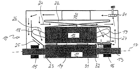
Fig. 1 shows a schematic longitudinal section of a
preferred exemplary embodiment of a high-speed, cooled
electric machine according to the invention. The
electric machine 10 comprises a rotor 11, which is
mounted in two bearings 15 and 16 by a rotor shaft 13
such that it can rotate about an axis of rotation 17.
The rotor 11 is surrounded coaxially by a stator 12
which is provided at the ends with winding overhangs 18
and 19 and of which, in Fig. 1, for reasons of
simplicity, only t:he upper half is shown. Rotor 11 and
stator 12 are separated from each other by an air gap
14. Arranged in the upper region of the machine 10 is a
cooler 20, through: which a cooling medium, preferably
air, flows. The flow of the cooling air through the
cooler 20 is effected by an additional fan 21 which, in
the example shown, is placed upstream of the cooler 20
CA 02355427 2001-08-16
- 5 -
in the flow direction, but can also be arranged
downstream of the Gaoler 20.
A significant feature of the cooling concept according
to the invention is, then, the use of two largely
mutual independent cooling circuits 25 and 24 for the
rotor 11 and stator 12. In this way, each of the two
components is supplied with cold air. The inflow of
already heated air from the rotor 11 into the stator 12
or vice-versa, which is associated with mostly high
losses, is therefore not required, which firstly
permits the efficient cooling of both components to be
achieved, and also a reduction in the fluidic losses as
compared with conventional cooling concepts.
In parallel with the paths of the rotor or stator air
(cooling circuits 25 and 24), there is an additional
cooling circuit 26, via which the winding overhang 18
on the cold gas side is cooled and the air gap 14 is
flushed. Uncontrolled heating of the air in the
interior of the air gap 14 is therefore avoided, and
the frictional output, which is considerable in the
case of machines with a high circumferential speed, is
dissipated. In addition, a throttling element (e.g. a
labyrinth seal) (not illustrated in Fig. 1) for
regulating the air gap mass flow can be fitted at the
inlet or the outlet of the air gap.
Furthermore, there is preferably a fourth cooling
circuit 27, via which the winding overhang 19 on the
"hot" machine side is supplied with cold air.
The cooling concept: sketched in Fig. 1 has two pressure
sources: the external additional fan 21, which can be
controlled independently of the machine 10 and which is
connected upstream or downstream of the cooler 20,
compensates for t:he pressure losses arising in the
stationary componE~nts, while an impeller (blading
system 23) fitted t:o the rotor 11 compensates for the
CA 02355427 2001-08-16
- 6 -
pressure losses arising from the flow through the
rotor.
In the case of machines with high circumferential
speeds, the entry of the cooling medium into the rotor
11 is always a critical component. High differential
speeds between the fluid and the rotating wall can
cause significant flow separations and therefore high
pressure losses. These exceed the pressure built up by
the external fans (21) conventionally used, under
certain circumstances by a multiple, so that the mass
flow required for the cooling can ultimately not be fed
into the rotor 11. In order, firstly, to keep the entry
losses as low as possible and, secondly, also to
produce a build-up of pressure which compensates for
the friction losses in the rotor 11, a radial or
diagonal blade sy~;tem 23 fastened to the shaft l3 is
fitted at the "cold" end of the active rotor part. The
flow through the rotor 11, and its cooling, are carried
out through axial r_ooling ducts 31, which open into a
radial exit gap 32 at the "hot" machine end of the
rotor 11.
In the cooling of the stator 12, in principle various
concepts can be employed, but are intended to have, as
a "common denominator", a means of sealing them off
from the air gap 14, so that the separation of the
rotor and stator cooling medium flows (cooling circuit
24, 25) is ensured. The principle is to be shown here
using the example of "tangential" segmentation of the
radial cooling slats of the stator 12 (Fig. 2). This
intrinsically offers an asymmetrical cooling concept,
since the air management can be configured very
flexibly and easily integrated into the overall
concept. The inflow and the outflow of the collecting
and distributing ducts fitted to the rear of the stator
by means of a collecting and distributing device 22 can
in principle be placed on any desired side of the
machine.
CA 02355427 2001-08-16
_ 7 _
Furthermore, this cooling scheme produces a very
homogeneous temperature distribution in the stator 12.
The supply of cooling air and the discharge of the
heated air are carried out by the collecting and
distributing ducts. (22) on the rear of the stator,
already mentioned and sketched in Fig. 2. The
distributors are fed from the "cold" machine side,
while the collectors discharge the air to the "hot"
side (cf. Fig. l). Starting from the cold air
distributors, in each case one half of a slot segment
28, 29 is flowed through from the outside to the inside
(arrows in Fig. 2). Underneath the conductor rods 30 of
the stator 12, a deflection through 180° takes place,
and then the outflow into the warm air collector. Here,
it is to be noted that the stator slots have to be
sealed off with respect to the air gap 14. This can be
implemented, for example, by means of a cylindrical
insert ("air-gap cy7.inder").
Overall, the invention results in a cooling concept for
a high-speed ele~~tric machine which permits both
efficient dissipation of the heat output and extensive
minimization of the ventilation losses. In addition,
this concept also results in considerable advantages
with regard to the operating costs of the machine,
since the cooling with air can be carried out under
atmospheric conditions and not, as in the case of
machines already available on the market, with helium
under pressure of about 4 bar or with methane under 40-
70 bar.
LIST OF DESIGNATIONS
10 Electric machine (high speed)
11 Rotor
12 Stator
13 Rotor shaft
14 Air gap _
CA 02355427 2001-08-16
15,16 Bearing (rotor)
17 Axis of rotation
18,19 Winding overhang
20 Cooler
21 Addii.tional fan
22 Collecting and distributing device
23 Blade system
24,..,27 Cooling circuit
28,29 Slot segment
30 Conductor rod (stator)
31 Cooling duct (axial)
32 Outflow gap (radial)