Note: Descriptions are shown in the official language in which they were submitted.
CA 02355529 2001-08-21
~TT,F OF THE INVEN~'ION
FASTENING MEMBER AND SIDING BOARDS AT'.i?ACHMENT STRUCTURE
BACKGROUND O>=' THE INVENTION
Meld of the Invention
The present invention relates to a fastening member that.
is disposed at: an upper rabbeted horizontal edge and a lower
rabbeted horizontal edge of a siding board. for mounting the
siding board to a framework with an underlayment being
interposed between, a siding boards attachment structure
employing the same, a starter member (that is a starter) that
is disposed at a. 7_owermost end of the ~~i.din.c~ boards attachment
structure, and further relates to a method of at tacking sidi.n.g
boards.
~i~sc~.~l.~~.~._~~kgrc~~nd
Conventionally, there exisi~s a siding boards attachment
structure 90 as shown in Figs. 18 to 2:1 .in which a plurality
of siding boards 2 are fixed to a framework with an underlayment.
~3 being interposed between by using a fastening member 9 (Fig,.
17) .
In such a siding boards attachment structure 9U, the
fastening member 9 is disposed to bridge over a joint portion
of upper and lower sid:i.ng boards 2, that is, a portion between
an upper rabbeted hori~,ontal edge 21 and a lower rabbeted
horizontal. edge 22, of the siding boards 2 as i1.1_ustrated in Figs.
1~) and 21 so as i:o mount the siding boards 2 to the frameworlc
1
CA 02355529 2001-08-21
with the underlayment 8 being interposed between.
It should be noted that a furring strip is illustrated
in Figs. 18 to 21 as the under_layment 8.
As il:Lustrated in L~'igs. 17 to 21, the fastening member
9 includes a base plate portion 91 abutting on rear side surfaces
26 of siding boards 2 that are vertically disposed, a support
portion 92 that is provided to erect frontward from the base
plate portion 91, an upper board engaging portion 93 that is
bent in an oblique upward direction from the support portion
92, and a lower board engaging portion 94 that is bent in an
oblique downward direction from the support portion 92 . A front
flat plate portion 934 abutti..ng on. a roar. surface of an overlying
tongue portion 226 of a lower overlying tongue portion of the
upper siding board 2 is formed .i.n front of the upper board.
engaging portion 93 and the lower board engaging portion. 94.
The base plate portion 91 includes a nail hole 98 and a
screw hole 99 for inserting thF~rein a nail 41 and a screw 42,
respectively, For fixing the fastening member 9 to the framework
with the underlayment 8 being interposed between.
..?.0 As illustrated in Fig. 1.7, t=he base plate portion 91
includes a sloped portion 91.1 at an upper portion thereof that
i_s curved in an oblique rearward direction and further a lower
leg portion 912. at a lower. end portion thereof that i.s bent
rearward at an angle of approximately 90°. A central plate
?.'~ port-i.on 913 is provided between the sloped portion 911. and the
Lo~~~er leg portion 91.2 fo:r connecting these members and further
2
CA 02355529 2001-08-21
abutting on the rear side surfaces 26 of the siding boards 2.
The support portion 92 is erected from the central plate portion
913.
The nail hole 98 is formed on the sloped portion 911 and
the screw hole 99 is provided on the central plate portion 913
formed between the sloped portion 911 and the support portion
92.
When the fastening member 9 i_s .fixed to the framework with
the underlayment 8 being interposed between, the fastening
member 9 is fixed to the framework with the unde.r_l.ayment 8 being
interposed between by the nail. 41 or the screw 42. More
parti.cul..ar.ly, when using t..he nail 41, the fastening member 9
is fixed to the framework by piercing the nail 41 through the
nail hole 98 and driving the nail_ 47_ to the framework with the
underlayment 8 being interposed between in an oblique downward
direction, as illustrated in Figs. 1.8 and 19.
When using the screw 4?_, the screw 42 is pierced through
the screw hole 99 and screwed into the framework with
lmde.rlayment 8 being interposed between for_ fixing the
fastening member 9 to the framework with the under_l.ayment 8
being interposed between as illustrated in Figs. 20 and 21.
In this manner, the fastening member 9 is arranged so that
a person performing the construct.i.on may freely select either
f i xing using a nail 41. ( figs . 18 and 19) or fixir~rl using a screw
4a ( Figs . 20 and 21 ) dependi.ng on various conditions at the time
of performing construction.
3
CA 02355529 2001-08-21
However, such a fastening member 9 exhibits the following
drawback.
The closer the nail 41 or the screw 42 is disposed to the
support portion 92 that receives the load, the larger fixing
for_~ce of the fastening member 9 to the framework against load
of the siding board 2 or wind pressure is.
Thus, in case of that the nail hole 98 and the screw hole
99 are disposed at posi_ti_ons at which a distance from the nail
hole 98 to the support portion 92 and a distance from the screw
ho1_e 99 to the support portion 92 are different, the fixing force
against load or wind pressure will differ between fixing by the
nail 41 anal .fixing by the screw 42..
In the .fastening member 9, the nail hole 98 i.s formed on
the sloped portion 911 whi_l~e the screw hole 99 is formed. on the
rentra.l_ plate portion 91.3, resperti.ve~_y (Fig. 17) . That is,
the nail hc.~le 98 is remoter from the support portion 92 than
the screw hole 99. Thus, the fixing force when fixing is
performed by the nail 41 (Figs. 18 and 19) will be smaller than
the .fix.ing force when fixing is performed by the screw 42 (Figs.
?. 0 2 0 and 21. ) .
In the siding boards attachment structura 90 employing
the fastening member 9, there i_s a difference i.n fastening
forces of the siding board 2 to the framework between using the
na.i.l_ 41_ and using the screw 4?_ . Consequent:Ly, performances such
?5 as wind. pressure-resistance and ot=hers will vary depending on
means for f.ixi_ng the fastening member 9.
4
CA 02355529 2001-08-21
In order to prevent producing partial differences in
fastening force of sid.i.ng boards in a single building, it will
be necessary to unify the .fixing means for performing
construction, either the nail 41 or the screw 42. Farther it
is not preferable that di fferences in fastening forces of siding
boards exist between each building. It will therefore be
necessary to unify the fixing means f_or performing r_onstruction
when a plurality of bui~_dings are built.
7. o ~~~~=CNV~L'~.~9~I
An object of the present invention is to provide a
fastening member which cai_ises hardly any d.i_f.ferenr_es in
fastening force of. siding boards owing to differences in means
for_ fixing the fittings t:o a buit.ding frame, an exterior wa_Ll
l_5 construction structure using the same, a starter member, and
further a method of attaching siding boards.
According to one aspect of the invention, a fastening
member is disposed to bridge over an upper rabbeted horizontal
edge of a lower. siding board and a lower rabbeted horizontal
20 edge of an upper siding board fo.r mounting the siding boards
to a framework of a building with an u.nderlayment being
interposed between,
wherein. the fastening member includes a base plate
t~ort.i.on abutting on rear side surfaces o.f siding boards that
25 are verti.cal.ly disposed, a support portion that .is provided t=o
erect frontward from th.e base plate portion, an upper board
CA 02355529 2001-08-21
engaging portion that is bent in an oblique upward direction
from. the support portion, and a lower board engaging portion
that is bent in an oblique downward direct:i.on from the support
portion,
wherein the base plate portion includes a nail hole and
a screw hole through which a nail and a screw are respectively
pierced for fixing the f.'astening member to the framework, and
wherein the nai.l_ ho7_e and the screw hole are provided at
position at which a distance from the nail hole to the support
portion and a distance from the screw hole to the support portion
are substantially equal.
It is a notable point: of the present iz~.venta_OIl that the
nail hole and the sr_rew hole are provided at position at which
a. distance from the nail hole to the support portion and a
1.5 di.stanre from the screw hole to the support portion a.r.e
substantially equal. That is, a vertical distance 8 from a
central plane of the support portion to the nail holE~ and a
vertical distance ~3 from the central plane of the support
portion to the screw hole are substantially equal (see rig.
2 (F3) ) .
It should be noted that the following explanations will
be made supposing that a side of the fastenine~ member itself
on w.h:i.ch the nail hole i.:s formed is the "upper" side and the
opposite side i s th.e "lowe:r'" side, when viewed from the support
2'_~ porti.~~n, for de.f_ini.ng respective names of portions.
The screw hole i.s formed on the Side which is opposite
6
CA 02355529 2001-08-21
to the nail hole. That a_s, since the screw hole is provided
downward o.f the support portion, the direction of the fastening
member needs to be turned upside down when performing fixing
using the screw. In this case, the upper board engaging portion
will engage the lower siding board and the lower board engaging
portion will engage the upper siding board (see Fig. 6).
With this arrangement, the positiona.l relationship of the
nail and the screw from the support portion will be
substantially identical with no matter which the nail or the
screw is used.
Working effects of the present invention will now be
explained.
As explained above, the nail ho l.e and the screw hole are
disposed i.n the above fastening member at positions at which
distances between t:he holes and i:he support portion are
substantially equal. Thus, there is almost no differences i.n
fixing force against load of the upper siding board or wind
pressure between fixing the fastening member by the nail and
fixing the fastening member by the screw.
There is almost no differences in fastening force of_
siding boards between. fixing the fastening member by the nail
and fixing the fastening member by the screw when arranging t:he
exterior wall construction structure. That is, no drawbacks
such as :i.solat:ion or fal.l..i ng off of siding boards are cau> ed
i 5 by changing means for_ .fixin.e~ the fastening member. For instance,
performances such as wind pressure-res~_stance of siding boards
7
CA 02355529 2001-08-21
attachment structures will not vary depending on means for
fixing the fastening member.
The fastening member is further advantaged in than easy
construction is enabled since a person performing the
construction may freely select the fixing means, either nails
or_ screws, in accordance with various conditions at the time
of con structions.
As explained so far, it is possible to provide a fastening
member with which hardly any differences in fastening force of
siding boards are caused owing to differences in means for
fixing the fastening member to the framework.
.~~.~~~S~J,~ T I9~L.~~'.~~I ~~~
A more complete appreciation of th~ i..nvention and many
10 of the attendant: advantages thereof w.il_1 become readi_:Ly
apparent with reference to the foli.owing detailed description,
particularly when considered i_n conjuncti_on with the companying
drawings, in which:
Fig. 1 is a perspective view of a fastening member
?.0 according to Embodiment 1;
Fig. 2(.A) is a front view of the fastening member
according to Embodiment l;
Fi.c~. 2 (B) is a sect=lOIlci 1. view seeYl from a direction as
i_mdicated by the arrow along .line C--C of F.i_g. 2 (A) ;
25 Fi.g. 3 is a perspect=ive explanatory view of a siding
boards attachment st:ruct:ure i.n which the fastening member of
8
CA 02355529 2001-08-21
Embodiment 1 is fixed to an u.nderlayment by a nail;
Fig. 4 is a l.ongitud.inal sectional explanatory view of
the siding boards attachment structure in which the fastening
member of Embodiment 1 is fixed to an under_layment by a nail;
Fig. 5 is a perspective explanatory view of a siding
boards attachment structure in which the fastening member of
Embodiment 1 i_s fixed to an underlayment by a screw;
E'ig. 6 is a long:itudi.nal sectional explanatory view of
the siding boards attachment structure in which the fastening
member of Embodiment 1 is fixed to an underlayment by a screw;
Fig. 7 is a perspective view of a siding board of
Embodiment l;
Fig. 8 i.s a longitudinal sectional view of a lower end
portion of the sid.i.nc~ boards attar_hment structure of Embodiment
1.5 l;
Fig. 9 is a perspective view of a starter member. of
Embodiment 1;
Fig. 10 (A) is a perspective view of a crown plate of the
stars=er member of Embodiment 1;
Fig. 10(B) is a perspective view of a notched groove of_
a leg plate of Embodiment 1;
E'ig. 11 is a perspective view of a fastening member of
Embodiment 2;
Fig. 1.2. is a perspective view of a fastening membe:r_ of
?_5 Embodiment 3;
Fi.g. 13 is a perspect.i.ve View o.f a crown plate of the
9
CA 02355529 2001-08-21
starter member of Embodiment 4;
Fig. 14 is a front view of a fastening member of Embodiment
5;
Fig. 15 is a perspective explanatory view of a siding
boards attachment structure of Embodiment 5;
Fig. 16 is a lateral sectional explanatory view of a
siding boards attachment structure of Embodiment 5;
Fig. 17 is a perspective view of a fastening member
according to the prior art;
Fig. 18 is a perspective explanatory view of a siding
boards attachment structui:e in which the fastening member of
the prior art is fixed to an underlayment by a nail;
Fig. 1.9 is a l.ongitudi.nal sectional explanatory view of_
the siding boards attachment structure in which the .fastening
1 5 member of th.e prior. art is fixed to an underlayment by a nail;
Fig. 20 is a perspective explanatory view of a siding
boards attachment structure in which the fastening member of
the prior art is fixed to an underlayrnent by a screw; and
Fig. 2.1 is a longitudinal sectional explanat=ory view o:f
the siding boards attachment structure in which the fastening
member of the prior art is fixed to an underlayment by a screw.
~.~R~PT I ON-,9~._ TI-IE PRE FERRED ~MBOD~.MEN_'~ z.
The preferred embodirnents wil.:l. now be described with
reference to the accompanying drawings, wherein like reference
numerals designate corresponding or identical elements
CA 02355529 2001-08-21
throughout the various drawings .
It is preferable that the base plate portion includes an
upper abutting portion and a lower abutting portion that abut
the underlayment at its upper and lower portion, an upper rising
portion and a lower rising portion that are respectively formed
in a frontward rising manner from the upper abutting portion
and the lower abutting portion, and a central plate portion
being installed to connect: the upper rising portion anal the
lower rising portion and abutting against the rear side surfaces
of the siding boards, wherein the support portion is formed to
be erected from the central plate portion.
With this arrangement, the siding boards may be mounted
to the framework with a clearance formed between the rear side
surfaces o.f the siding boards and the underlayments. A
J_5 vent.i_lation layer w_i.7_1 be accordingly formed between. the siding
boards and the underlayments for improving 'the durability of
the siding boards attachment structure.
It is further preferable that the upper rising portion
and the lower rising portion include a horizontal plane portion
that is arranged to form a subst=antiall.y right angle with
respect to the central plate portion.
With this arrancJement, it is possible to obtain a
fastening mernber which is easy to be construct:ed.
For fix..i.ng the fastening member_ to the framework, the
fastening member is fir_st~ engaged at the lower. siding board.
More particularly, the upper rabbeted horizontal edge of the
11
CA 02355529 2001-08-21
lower exterior wall p7.ate is inserted into space formed by the
central. plate portion, the support portion and the lower board
engaging portion of the fastening member..
By engaging the lower board engaging portion at the upper
rabbet:ed horizontal edge of the siding board and hitting the
fastening member from above by a hammer or the like, the upper
rabbeted horizontal edge of the siding board and the fastening
member are fitted.
As described above, since the fastening member .includes
1(J the horizontal plane portion in the upper rising portion and
the lower -rising portion thereof, the horizontal plane portion
may be h.i.t from above. W.i.th this arrangement, the .f_asteni.ng
rnember may be easi.l.y and re J.iably .fitted to the siding board.
In case of that the irast.eni.ng member is used with the nail
hole being positioned above the support portion, th.e fastening
member is fitted to the s:i.di.ng board by hitting the horizontal
plane portion formed in the upper_ rising portion. On the other
hand, in case of that the fastening member is used with the screw
hole being positioned above the support port=ion, the Lastening
member is fitted to th.e siding boa.r_d by hitting the horizon.ta.l
plane portion formed in the lower rising portion.
It i.s preferabl.e that the fastening member includes
protruding port:i.ona proj ec.ting frontward frorn an upper end of
l:he upper abutting po.r:ti.on and from a lower encJ of the lower
abutting portion (see Fig. 12).
W.i.t:h this arrangement, s:im.i.1_arly, the f:asteni.ng member
12
CA 02355529 2001-08-21
may be easily and reliably fitted to the siding board by hitting
the protruding portion.
It is further preferable that the upper r.i.sing portion
includes a sloped portion wherein the nail hole is formed on
the sloped portion.
With this arrangement, the nail may be pierced through
the nail hole and be dr_i.ven to the framework with the
underlayment being interposed between in an oblique downward
direction. Thus, the fastening member may be reliably fixed
to the framework and reliably engaged at the lower siding board.
It is preferable that the upper abutting portion and the
lower_ abutting portion :inc:l.ude an abutting surface that i.s
substantially horizontal to the central plate portion (see Figs.
1 anal 11 ) .
With this arrangement, a contact surface of the upper
abutting portion and t:he lower abutting portion with the
underlayment may be large, and it is possible to prevent the
upper abutting portion and the lower abutting portion from being
buried into t=he underlayment. More particularly, also i_n case
of that the unde.rlayment is a soft mater.i.al such as a foamed
plastic resin board, the upper abutting portion and the lower
abutting portion of the fastening member wi_1.1 not be buried into
the underlayment, and it i.s possible to prevent the fastening
member from sinking ir~.t~o the undor.l_ayment.
2.5 Thus, the siding boards may be stably fastened to the
f:ramework with the underlayment being :i.nterposed between.
7_ 3
CA 02355529 2001-08-21
It is preferable that the fastening member is of a shape
that is elongated in lateral directions such that a plurality
of studs of 'the framework. that are disposed in a laterally
aligned manner may be connected and fixed (see E'i.gs. 14 and 15) .
With this arrangement, laterally arranged siding boards
may be reliably mounted to the framework also in case of that:
left rabbeted Vertical edges or right rabbeted vertical edges
of the siding boards are not: disposed on the studs of the
framework.
More particularly, in case of that such a fastening member
is employed for a siding boards attachment structure using a
wood f_.rame const..r.uction, it is necessary to dispose the
fastening member. at a portion at which a stud. is provided for
secur_i.ng strength. On the other hand, the fastening member
needs to be disposed on the upper rabbeted horizontal edge and
the lower rabbeted horizontal. edge on a corner portion of the
siding board.
At this time, in case of that the left rabbeted vertical
edge or_ the right rabbeted Vert.i.cal edge of the siding board
?_0 is not disposed on the stud, that is, in case of that the corner
portion of the siding board is not disposed on the portion where
a stud is present, the fastening member may not be disposed on
a portion where the stud i5 present and the coxwner portion of
the siding board is located in case of that the fastening merni:~er_
is short.
Thus, by arranging th.e fasten=i_ng member to be a shape that
14
CA 02355529 2001-08-21
is elongated in lateral d:i.r_ections fo.r enabling connection and
fixing of a plurality of studs, it will be possible to arrange
a siding boards attachment structure exhibiting satisfactory
strength.
Accord.i.ng to another aspect. of the invention, a siding
boards attachment structure includes a fastening member being
disposed on an upper rabbet:ed horizontal edge and a lower
rabbeted horizontal edge of a siding board for mounting the
siding board to a framework of a building with an underlayment
being interposed between,
wherein the fastening member includes a base plate
portion abutting against rear side su.r_faces of siding boards
that are ver_t=ically disposed., a st-lpport portion that is provided
to erect f.rontward from the base pl ate portion, an upper board
engaging portion that is bent i.n an oblique upward direction
from a front end portion of the support portion, and a lower
board engaging portion that is bent in an oblique downward
direction frorn'the support portion,
wherein the base plate portion includes a na.i..l hole and
a screw hole through which a nail and a screw for fixing the
fastening member. to the framework are pierced and that are
disposed at positions at which a distance from the nail hole
to the support portion and a distance from the screw hole to
the support portion become substant:ia.lly equal,
wherein the fastening member is arranged such that the
nail hole is disposed upward of the support port=ion with the
CA 02355529 2001-08-21
nail being fixed while being pierced through the nail hole .in
case of that the fastening member is fixed to the framework by
the nail, and
wherein the fastening member is arranged such that the
screw hole is disposed upward of the support portion with the
screw being fixed while being pierced through the screw hole
in case of that the fastening member is fixed to the framework
by the screw.
The screw hole of the above fastening member is formed
downward of the support portion. Thus, when performing.fixing
by the screw, the directloTl Of the fastening member is turned
upside down, In this case, the uppe.r_ board engaging portion
will engage the lower siding board. while the 7_ower board
engaging portion will engage the upper siding board (see Fig.
6) .
In the siding boards attachment structure, the distances
from the support portion to t=he nail and to the screw are
substantially equal, in the cases of that fastening member is
fixed by the nail and that the fastening member is fixed by the
2_0 screw.
'i'hus, hardly any differences in fixing fo.r_ce are caused
in case the fastening member_ i~~ fi.tted by the nail and by the
screw. In other word, hardly any differences in fastening force
oa si.ding boards wi_11 be caused depending on. means for fixing
2.5 the fastening member.
Thus, it is possible to provide a siding boards attachment
16
CA 02355529 2001-08-21
structure wwith hardly any differences in fastening force of
siding boards being caused depending on means for fixing to the
framework.
Tt. is preferable that t:he base plate portion of the
fastening member includes an upper abutting portion and a lower
abutting portion that abut the underlayment at its upper and
lower portion, an upper rising portion and a lower rising
portion that are respective7_y formed in a frontward r.is.i_ng
manner from the upper abutting portion and the lower abutting
portion, and a central p7..at:e portion for connecting between the
upper rising portion and the lower rising portion and further
abutting against the rear side surfaces of the siding boards,
wherein the support portion is formed to erect from the central
plate portion.
1.5 With. this arrangement, a venti_l.ation 7..ayer will be formed
between 'the siding boards and the underlayments for impr_ovi.ng
the durability of the siding boards attachment structure.
It is further preferable: that the upper rising portion
and the lower rising portion include a horizontal plane portion
that is arranged to form a substantially right angle with
respect to the central plate portion.
~s described above, by hitting 'the horizontal plane
portion when fitting the fasten:i.ng member t;o the upper rabbeted
hori.zon.tal edge of the siding board at. the tame oi' construe.. ti. on,
fitting may be easi.l.y and. reliably performed. It .is thus
possible to obtain a fasten.i_ng member ena:bl.i_ng easy
1. 7
CA 02355529 2001-08-21
construction.
It is preferable that the fastening member includes a
protruding portion projecting frontward .from an upper end of
the 'upper abutting portion and from a lower end of the lower
abutting portion.
With this arrangement, t:he fastening member may be
similarly fitted to the .siding board in an easy and reliable
manner by hitting the protruding portion.
It is further preferable that the upper_ rising portion
includes a sloped portion wherein the nail hole is formed on
the sloped portion.
With this arrangement, pressurizing force of the nail.
that. .is directed in an ob:l i clue downward direction with respect
to the framework wi.7_1 act on the .fastening m.Ember when using
the nail. It is thus possi_bl.e to obtain a siding boards
attachment structure in which the fastening member is reliably
fixed to the framework and in which it i.s reliably engaged at
the lower siding board.
It is preferable that: the upper abutting portion and the
_20 lower abutting portion inc:l~zde an abutting surface that is
substantially horizontal to the central plate portion.
With this arrangement, i.t is possible to prevent the upper
abl.ztting portion a~ud the :Lower abutting portion front cutting
into the underlayment, and to yrevent the fastening member from
si.nki.ng into the underlayment.
It is thus possi.b:l_e to obtain a siding boards attachment
18
CA 02355529 2001-08-21
structure in which siding boards are stably fastened to the
framework with the underlayment being interposed between.
It is preferab7_e that the fastening member is fixed to
connect a plurality of studs of the framework that are disposed
to be laterally aligned such that two adjoining siding boards
are engaged by a single fastening member..
With this arrangement, it is possible to obtain a siding
boards attachment strur_ture exhibiting satisfactory strength
also in case a left rabbeted vertical edge or a right rabbeted
vertical edge of the siding board is not disposed on the stud
of the framework.
The siding boards attachm.en.t structure is preferabJ.y a
COIIStrur_ting structure employing a framework wall construction
method.
With this arrangement, it is poss.ibJ_e to obtain a sid.i.n.g
boards attachment structure enabling easy construction. It i_s
also possible to obtain a siding boards attachment structure
exhibiting satisfactory strength.
It should be noted that details of the framework waJ_1
2.0 construction method will. be described later.
It is preferable that a lower rabbeted horizontal edge
of a lowermost siding board is located to be remote from the
ground surface.
With this ar_i:angemFnt, it is possible to prevent the
lowermost siding board from. absorbing moisture di.rectJ_y from
t=he ground surface, thus corr_osi.on or degradat~.ion of the si_d.ing
19
CA 02355529 2001-08-21
board can be prevented.
'thus, it is possible t:o obtain a siding boards attachment
structure exhibiting superior_ durability.
It is further preferable that a starter member. that is
fixed to the framework together with the lowermost fastening
member is disposed at a lowermost end of the siding boards
attachment structure.
With this arrangement, it is possible to reliably obtain
a siding boards attachments structure with the lowermost siding
board being remote from the ground surface by a specified
distance. Since a continuous footing of the siding boards
attar_hment structure ma.y be hidden thereby, the external.
appearance of design may also be improved.
The starter member preferably includes a l.eg p~.ate that
1.5 is lor_ated to be proximate to the ground s~.~.rface, a. bottom plate
abutting against a lower_ end portion of the fastening member,
and a back plate to be fixed to the framework,
wherein the leg plate is of a length that is substantially
identical. to a distance between the exterior wal.7.. plate mounted
?0 to the fastening member and the ground surface.
The "lower end portion of the fastening member" denotes
an end portion. that is located downward when the fastening
member is d:i.sposed at: the framework.
Mo.r_e particularly, when fixing the fasteruincJ member by
2.'~ a nail, the lower end of the lower abutting port_i.on of the
fastening member abuts on. the bottom p7_ate of the star.~t~er member
CA 02355529 2001-08-21
(see Fig. 8), and when fixing the fastening member by a screw,
the direction of the fastening member. is turned upside down so
that an upper end of the upper abutting portion abuts on the
bott=om plate.
With this arrangement, it is possible to obtain more
easily and reliably a siding boards attachment structure in
which the siding board at the lowermost end is remote from the
ground surface by a specified distanr_e.
According to another aspect of the invention, a starter
member is used together with a lowermost fastening member and
is disposed at a lower end portion of a siding boards attachment
structure,
wherein the starter member includes a leg plate that is
located proximate to the ground surface, a bottom p1_ate abutting
against a lower end portion of the fastening member, and a back
plate to be fixed to the framework,
wherein the leg plat=a is in a length that is substantially
identical to a distance between the exterior wall plate mounted
1.o the fastening member and the ground surface (see Figs. 8 and
2. 0 9 ) .
By using the starter member of the present invention, the
siding board at the lowermost end may be easily and reliably
constructed to be remoto from the ground si.zr.face by a specified
distance. The starter member is furt~her_ capable ofi.' hiding a
continuous footing of the siding boards attachment structure,
thus the externa_I_ appearance of design can be improved.
21.
CA 02355529 2001-08-21
It is preferable that the starter member includes a crown
plate projecting frontward from the back plate .for abutting
against a rear side surface of the siding board.
With this arrangement, the starter member may be easily
and stably constructed.
The crown plate preferably includes ventilating ho7_es.
With this arrangement, outside air is introduced to
between the rear side surfaces of the siding boards and the
underlayments so that ventilation of 'the interior of. the siding
boards attachment structure may be permanently pe.r.formed.
Thus, the durability of the siding boards attachment structure
may be i.mp.roved.
It is preferable that: the venti7.at.i.ng holes are cocrered
with mesh-like bodies.
With this arrangement, it. i.s possi.ble to prevent vermin
such as termites or bees from entering tl-ie rear side of the siding
board through the ventilating holes. 'Thus, it is possible to
prevent degradations of the siding board, underlayrtient, the
framework and the like.
It is preferable that the leg plate is formed with a
notched groove for. adjusting its length.
With this arrangement, the l.eg plate may be cut at the
notched. groove for easily adjusting the length thereof.
The notched groove is preferably wormed at a plurality
of spots. In th:i_s case, the length of th.e leg plate may be
adju~st..ed in accordance with various conditions for
22
CA 02355529 2001-08-21
constructions such that: the siding boards attachment structure
may be constructed.
According to the other aspect of the invention, a method
of attaching siding boards includes
a first process of fixing a fastening member at a
lowermost stage of the siding boards attachment structure to
a framework with an underlayment being interposed between by
a nail or a screw,
a second process of engaging a lower rabbeted horizontal
edge of a siding board at the fastening member for disposing
the siding board witrn the rear side surface thereof opposing
to the framework, and
a third process of dispos.i.ng another fastening member to
an upper rabbeted horizontal edge of th.e siding board and fixing
the fastening member to the framework with the underlayment
being interposed between by a nail or a screw,
wherein the second proces:~ and third process are
sequentially repeated after performing the third process,
wherein in case of that nails are used in the first process
and third process, the nail ho7_e i.s disposed upward of. the
support portion for engaging the fastening member to a lower
siding board and the nail. is pierced through the nail hole for
flX1_I1CJ trl-C.' fastening member to the :fr_amework with the
under l.ayment being interposed between,
~~~hil.e in case of that screws are used in the first process
and third process, the screw hole is disposed upward of the
23
CA 02355529 2001-08-21
support portion for engaging the fastening member to a lower
siding board and the screw is pierced through the screw hole
for fixing the fastening member to the framework with the
underlayment being interposed between.
It is a notable point of. the method of attaching siding
boards that in case of that the fastening member is fixed by
nails in the first process and. third process, the nail hole is
disposed upward of the support portion while the screw hole .is
disposed upward of the support portion in case of that the
1.0 fastening member is fixed by screws.
'Thus, in case of that tree screw hole is provided downward
of the support portion, that :is, on an opposite side of. the nail
hole, the direction of the fastening member needs to be turned
upside down when fix.i.ng is performed with the screw in contrast
1.5 t:o a case in. which fixing is performed with t:he nail. In. this
case, the upper board engaging portion will engage the lower
siding board and the lower board engaging portion will engage
the upper siding board.
The positional rel.ati_onship of the na:i1 and the screw from
20 the support portion will be substantially identical, when the
nail and the screw is used. Thus the fixing force of the
fastening member to the framework will be stable.
Thus, according to t:he above method of constructing
ext:er_ior walls, it is possik>le to construct a siding boards
25 attachment structure with. which hardly any differences in
fastening force of siding boards wil_1 be caused owing to
24
CA 02355529 2001-08-21
differences in means for fixing the fastening member to the
framework.
Embodiment 1
The fastening member and the siding boards attachment
structure according to embodiments of the present invention
will now be explained with reference to Figs. 1 to 10(B).
Figs. l, 2 (A) and 2 (B) are exp:Lanatory views of a
fastening member 1 of the present example, Figs. 3 to 6 are
explanatory views of_ a siding boards attachment structure 7
using the fastening member 1, E'ig. 7 is an explanatory view of
a siding board 2 used in the siding boards attachment strur_tu.r_e
7, and Figs. 8 to 10 (B) are explanatory views o:E a starter member
6 used in the si.d.ing boards attachment structure 7.
It should be noted that as mentioned above, the following
explanations will. be made supposing that a side of the fastening
member 1 itself on which a nail hole 18 is formed is an "upper"
portion and the opposite side is a "lower" portion, when viewed
from the support portion, for. defining respective names of
portions.
As illustrated i.n Figs. 3 to 6, the fastening member 1
is disposed to bridge from an. upper rabbeted horizontal edge
21 of a siding board 2 than is disposed on a lower side to a
lower rabbeted horizontal edge 22 of a siding board 2 that. is
d_i.sposed on an upper side, and i.s for mounting the siding boards
2 to a stud 31 (framework) with an underl.ayment 3 being
CA 02355529 2001-08-21
interposed between.
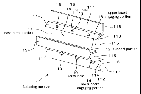
As illustrated in Figs. 1 to 4, the fastening member 1
includes a base plate portion 11 abutting against rear side
surfaces 26 of siding boards 2 that are vertically disposed,
a support portion 12 that is provided to erect frontward from
the base plate portion 11, an upper_ board engaging portion. 13
that is bent upward from the support portion 12, and a lower
board engaging portion 14 that is bent downward from the support
portion 12. A front flat plate portion 134 abutting against a
rear surface of an overlying tongue portion 226 of a lower
overlying tongue portion of the upper siding board 2 is formed
frontward of the upper board engaging portion 13 and the .lower
board engaging portion 14.
The base plate portion 17_ incJ_udes a nail hole :18 and a
I_5 screw hole J.9 far piercing a. nail 41 and a. screw 42, resper_tiv~~ly,
through for fixing the fastening member 1 to the framework with
the underlayment 3 being interposed between.
As illustrated in Fig. 2 (B) , the nail hole 18 and the screw
hoJ_e 19 a.r_e provided at. positions where distances from the nail
hole 18 and the screw ho.l..e 1.9 to the support portion 12 are
substantially equal. More particularly, a vertical distance
A from a central plane of the support portion 12 to the nail_
hole 18 and a vertical distance ~ fronu the central p:Lane of the
support portion I_2 to the screw loJ.e 19 are substant:.ial.J.y equa:i..
As illustrated i.n Fi.gs . l., 2 (A) , 2 (B) , 4 and 6, the base
plate portion 11 includes an i:lpper abutting portion J.11 and a
26
CA 02355529 2001-08-21
lower abutting portion 112 that abut on the underlayment 3 at
its upper and lower portion. ~Ct further includes an upper
rising portion 113 and a lower rising portion 114 that are
respectively formed in a frontward rising manner from the upper
abutting portion 111 and the lower abutting portion 112.
The base plate portion 11 further includes a central plate
portion 115 for connecting the upper rising portion 113 and the
lower ri si.ng portion 1.14 and further abutting against the rear
side surfaces 26 of tr~.e siding boards 2, wherein the support
portion 12 is formed. to erect from the central plate portion
115.
As illustrated .in F'i.gs. 1 and 2(B), the upper rising
portion 113 and the lower rising portion 114 include horizontal.
plane portions 15, 16 that are arranged at a substantially right
1.5 angle with. resper_t to the r_entral_ plate portion 115.
Tree upper rising portion 113 includes a sloped portion
17 wherein the nail hole 18 is formed on the sloped portion 17.
The upper abutting portion 111 and the lower abutting portion
112. include abutting surfaces 116 and 117 that are substant=Tally
horizontal to the central. plate portion 115.
The fastening member 1 is manufactured by, for instance,
extrus_i.on molding of almminum.
The siding- boards s.ttachment structure 7 using the
fastening member 1 wi. a.l now be expl wined with reference to Figs .
3 to 8.
As illustrated i.n figs. 3 to 6, the siding boards
27
CA 02355529 2001-08-21
attachment structure 7 is arranged by disposing the :fasteni_ng
member to bridge .from the upper rabbeted horizontal. edge 21 of
the lower siding board 2. and the lower rabbeted horizontal edge
22 of the upper siding board 2 for mounting the sidp_ng boards
2 to the stud 31 of the framework with the underlayment 3 being
interposed between.
1~s illustrated in Figs. 3 and 4, in case of that. the
fastening member 1 is fixed to the stud 31 w.i.th the under_layment
3 being interposed between by the nail 41, the nail hole 18 is
disposed upward of the support portion 12 and the nail 41 is
pierced through the nail hole 18 and driven in an oblique
downward direction for fixing,
On the other hand, as i llus trated in Figs . 5 and 6, i_n
case of that the fastening member. 7. is fixed to the stud 31 with
the unde.rlayment 3 being interposed between by the screw 42,
the screw hole 19 is disposed upward of the support portion 12
and the screw 42 .i.s pierced through the screw hole 19 and screwed
in a horizontal direction for fixing.
The siding board ?_ constructing the siding boards
2..0 attachment structure '7 i.s a siding board of a four side ( left,
right, upper and :Lower sides) shiplap structure as illustrated
in E'ig. 'i . More partirul~.r.ly, th.e siding board 2 includes an
upper underlying tongue portion at the upper rabbeted
horizontal edge 21, a lower over.Lying tongue portion at the
lower rabbeted horizontal edge 22, a later_a7_ underlying tongue
portion at a right rabbeted vertical edge 23 and a lateral
2. 8
CA 02355529 2001-08-21
overlying tongue portion at a left rabbeted vertical. edge 24.
Caulking materials 29 for_ preventing penetration of water from
joint portions of siding boards 2 after construction are
attached on a front surface of the upper underlying tongue
portion and a front surface of the lateral underlying tongue
portion.
As illustrated in Fi.g. 8, a distance ~ between the lower.
rabbeted horizontal edge 22 of a siding board 2 that is di. sposed
at a lowermost stage and the ground surface 5 is set to be, for
instance, 6 inches in the siding boards attachment structure
7. As a means thereof, the starter member E~ is disposed at the
lowermost end of the s:i.di.ng boards attar_hme.nt structure 7
together with the fastening member 1 at the lowermost end.
As illustrated in Figs. 8 and 9, the starter member. 6
includes a l.eg plate 61 abutting the ground surface 5, a bottom
plate 62 abutting the lower end portion of the fastening member
1, and a back plate 63 f.or fixing on the underlayment 3.
ThF: bottom plate 62 is arranged at a position at which
it. i.s substanti_al.l.y the same height as the siding board 2 that.
is mounted to the fastening member 1 is to be disposed remote
from the ground surface 5 as .in. the above-explained manner. That
is, the bottom p:La.te 62 is formed at a position at which a
distance ,~ from a lower end portion 6i2 of the starter member
6 i.s, for instance, approxi_matei.y 6 inches.
The lower end portion of the leg plate 61, that is, the
lower end portion 612 of t:he starter member 6 i.s bent. backward
2. 9
CA 02355529 2001-08-21
to form a plane portion on a substantially identical plane as
the back plate 63 and is located to be proximate to the ground
surface 5 for improving the external appearance of design.
The starter member 6 includes a crown plate 64 projecting
frontward from the back plate 63 and abutting against .rear side
surfaces 26 of the siding boards 2. As illustrated in Figs.
8 and 9, the crown plate 64 includes a front flat plate portion
641. at a front end portion thereof and is provided with
ventilating holes 65 as illustrated in Fig. 10(A).
As illustrated in figs . 9 and 10 (F3) , the leg plate 61 i.s
formed with a notched groove 611 at a specified position such
that its .length is adjustable :in accordance with conditions at
construction sites. The notched groove 611 may be formed in
a hor.i.~ontal manner. at a position, for example, 4 inches from
7.5 the lower end portion of the 1_eg plate 67..
The siding boards attachment structure 7 (Fi_gs. 3 to 8)
is a constructing structure employing a framework wall
construction method, and in case of performing construction,
t:he framework is assembled in the fo.llowi.ng manner.
That is, a plural.i.t:y of square timbers in which sectional
dimensions are identical are used for f.i.rst assembling a
plurality of wa~_1_ frarnewor_ks 30. The square timber generally
has a sectional. dimension of 2x4 inches, and intervals between
studs 31 of the wall. I:Lamewo.rks 30 may be, for instance, 16,
2.0 and 2 4 inchr~s .
These wal:1 frameworks 30 are assembled on a continuous
CA 02355529 2001-08-21
footing 300 as a framework of a building (Fig. 8).
As illustrated in Figs . 3 to 6, under7_ayments 3 made, for
i_nst:ance, o.f foamed plastic resin boards having a thickness of
12 mm, are fixed to the wall. frameworks 30 from outside of the
framework by using nails of lengths of approximately 30 mm.
This is a simple constructing method in which construction of
heat-insulating materials is completed at the time of
constructing the siding boards without forming hearing walls .
It should be noted that oriented strand boards (OSBs) can
be used as the under_layments 3.
Particularly, the siding boards 2 are fastened to the
assembled wall frameworks 30, that is, the framework (studs 31)
with the un.der7.ayments 3 being interposed between i.n the
following manner..
In a first process, the fastening member 1 at the
lowermost stage of the siding boards attachment structure 7 is
fixed to a sill 32 with the underlayment 3 being interposed
between as illustrated in Fig. 8.
In this r_ase, waterprooa paper 33 .i.s adhered to an outside
surface of the underlaym.ent 3 by using a double-.faced adhesive
tape or the l.i.ke. Then, the starter member 6 is disposed such
that the lower end portion 612 thereof is proximate to the ground
surface 5 and the fastening member 1 i.s mounted on the bottom
plate 62 of the starter member 6 for fixing the fastening member
1. to the sil_1 32 with the underl ayment 3 being interposed between
(Fig. 8) .
31
CA 02355529 2001-08-21
Tn case of that the fastening member 1 is fixed to the
underlayment 3 by the nail 41, the nail hole 18 is disposed upward
of. the support portion 12 and the nail. 41 is pierced through
the nail hole 18 for driving the nail 41 in an oblique downward
direction for fixing tk~.e fastening member 1 to the sill 32 with
the underlayment 3 being interposed between as illustrated in
Fig. 8.
Un the other hand, in case of that the fastening member_
1 is fixed to the underlayment 3 by the screw 42., the screw hole
19 i.s disposed on upward of the support portion 12 and the screw
42 is .pierced through the screw hole 19 for screwing the screw
42. in a horizontal direct:.i.on for fixing the .fasteni_ng member
1 to the sill 32 with the underlayment= 3 l:~eing interposed between
(see Figs. 5 and 6).
In. a second proc?ss, the l.owe.r overlying tongr.ze port ion
of the lower rabbeted horizontal edge 22 of a siding board 2
that is to be disposed at a lowermost stage is engaged at the
upper board engaging portion 13 of the fastening member 1 to
be disposed to fare the underlayment 3 (see F'ig. 8).
For jo.ini.ng laterally disposed siding boards 2, the
siding beards 2 are fastened such that butt portions of the right
rabbeted vertical edge 23 and the l.ef:t rabbeted vertical edge
24 of the siding boards 2 are disposed at positions where studs
31 of the wall frameworks 30 are present: as i.llustra.t:ed in Fags .
3 and 5.
l:n this manner, in case of. joining in lateral directions,
32
CA 02355529 2001-08-21
the lateral overlying tongue portion of. the left rabbeted
vertical edge 24 of the right siding board 2. is overlapped onto
the lateral underlying tongue portion of the ri.grut rabbeted
vertical edge 23 of the left siding board 2, that has been fastened
before, and both are joined through right-and-left shiplap
jointing, as illustrated in Figs. 3 and 5.
In a third process, another fastening member 1 is disposed
on the upper rabbeted horizontal. edge 27_ of a siding board 2.
that is disposed on the 1_owermost stage in the above-described
manner, and is fixed to the stud 31 with the underlayment 3 being
interposed between by the nail 41 or the screw 42.
As i_l.lustrat=ed. i_n Fi.gs. 3 and 4, i_n case of fixing the
.fastening member 1 to the underlayment 3 by a. nail 41, the nai_1.
hole 18 i.s disposed upward of the support portion :12 and the
:15 fastening member 1 is engaged at the upper rabbeted horizontal
edge 21 of the lower si.di.ng board 2 . 'That is, the upper rabbeted
horizontal edge 21 of the .Lower siding board 2 is inserted into
space formed by the base plate portion 11, the support portion
7_2, and the 1_ower board engaging portion 14 o.f the fastening
member 7..
At this time, the lower board engaging portion 14 is
engac.~ed at. the upper .rabbet=ed horizontal. edge 21 of the siding
board 2 and the horizontal plane portion 15 formed at the upper
rising portion 7.13 of the fastening mernt~er_ 1 is li.ght:Ly hi.t frorn
above b;r a hammer or_ the like for fitting t:he fastening member
1 to th.e siding board 2 reliably.
33
CA 02355529 2001-08-21
The nail_ 41 is then pierced th..rough the nail hole 18 and
driven in an oblique downward direction for fixing the fastening
member 1 to the stud 31 with the uncierlayrnent 3 being interposed
between.
On the other hand, as illustrated in Figs. 5 and 6, in
case of fixing the fastening member 1 t=o the underlayment 3 by
a screw 42, the screw hole 19 is disposed upward of the support
port-.ion J..2 and the fastening member 1. is engaged at the upper.
rabbeted horizontal edge 21 of the lower siding board 2. That
is, the direction of the fastening member 1 is turned upside
down in contrast to the above-described case in which fixing
is performed by using the nail. 41 (Fi.gs. 3 and. 4) .
Then, the fastening member 1 is engaged at the upper_
rabbeted hor.izontal_ edge 21. o.f the lower_ siding board 2. That
i ~, the upper rabbeted ho.rizontaJ_ edge 21. of. the lower siding
board ?_ .i_s inserted into spare formed by the base plate portion
1 l., the support portion 7.2, and the upper board engaging portion
13 of the fastening member 1.
At this time, the upper board engaging portion 13 i.s
2.0 engaged at the upper rabbeted hori zon.tal. edge 21. of. the siding
board 2 and t:he horizontal plane portion 16 formed at the lovrer
rising portion 114 of the fa:~tening member 1. is lightly hit from
above by a harnrner or the like for fitting the fastening member
1. to the upper rabbeted horizontal edge 21 of the si.d.ing board
2 reliably.
The screw 42 is then pierced through the :crew hole 19
34
CA 02355529 2001-08-21
and. screwed in a horizontal direction for fixing the fastening
member 1 to the stud 31 with the underlayrnent 3 being interposed
between.
In this manner, in case of joining in vertical directions
as illustrated in Figs. 4 and 6, the lower overlying tongue
portion of the lower rabbeted horizontal edge 22 of the upper
siding board 2 is overlapped onto the upper underlying tongue
portion of the upper rabbeted horizontal edge 21. of the lower
siding board 2 that has been fastened before, and both are joined
through an upper-and-lower sh.i.plap jointing.
After completing the third process, the same processes
as the second process and third process are sequential_l.y
repeated,
The working effect of the present example will be
explained.
In the above fastening member 1, t:he nail hole 18 and the
screw hole 19 are disposed at positions where a distance from
the nail hole 18 to the support portion 12 and a distance from
the screw hole 19 to the support po:r. tion 1.2 become substantial.l.y
equal (Figs. 2(A), 2(B)). Thus, hardly any d:i.f.ferences a.re
caused in fixing force of the upper siding board 2 against load
or wind pressure in case of fixing the fastening member 1 by
the nail 41 ( Figs . 3 and 4 ) and the case o fixing the fas tening
merni~er_ :l. by the srr_ ew 42 ( Figs . 5 and 6 ) .
Thus, hardly any differences are caused in fastening
force of the siding boards 2 when construe~.ti.ng the si.d.i.ng boards
CA 02355529 2001-08-21
attachment structure 7 by fixing the fastening mettiber 1 by using
either the nail 41 or the screw 42. Tn other words, hardly any
diff_erenc:es are caused in fixing force of the upper siding board
2, no matter whether the siding boards attachment structure '7
is constructed by fixing the fastening members 1 using only
nails 41 or the siding boards attachment structure 7 is
constructed by Fixing the fastening members 1 using only screws
42.
More particularly, no drawbacks such as isolation or
falling off of siding boards 2. will be caused by varying the
means for fixing the fastening members 1. Particularly
performances such as wind-pressure resistance of the siding
boards attachment strur_ture 7 will not be varied depending on
means for_ fixing the fastening momber_s 1.
Since a person performing the construction may freely
select the fixing means for the fastening members 1, that is,
nails 41 or screws 42, i.n accordance with various conditions
in performing construction, easy construction is enabled.
The base plate portion 11 of the fastening member 1
includes the upper_ abutting portion 111, the lower abutting
portion 11.2., the upper rising portion 113, the lower rising
portion 114, and the central plate portion 115.
With this a:rranc.~emer~.t, a ventilation layer %1. is formed
between the re~.r side surfaces 26 of the siding boards 2 and
the un.derlayments 3 in the siding boards attachment structure
7 as i.ll.ust.rated in. Figs . 4, 6 and B, so that condensation i.s
36
CA 02355529 2001-08-21
prevented and the durability of the siding boards attachment
structure 7 is improved.
As illustrated in Figs. 8, 9 and 10 (A) , ventilating holes
65 are formed in the crown plate 64 of the starter member 6
disposed at the lowermo~>t. end of the siding boards attachment
structure 7.
Therefore, outside air '79 from below is introduced to the
venti7_ation layer 71 through the ventilating holes 65 and the
introduced outside air 79 is exhausted from above.
With this arrangement, it is possible to prevent
accumulation of humidity on rear sides of the siding boards 2
or on the under_l.aymonts 3, and corr_osa_on of the izndPrlayments
3 Ur studs 31. wi..ll not occur so that is possible to improve the
durabi)_ity of the siding boards attachment structure '7 largely.
Since the upper rising portion 113 and the lower rising
portion 114 of the fastening 'member 1 includes horizontal plane
portions 15, 16 that are arranged to form a substantially right
angle with respect to the central plate portion 115, easy
const.r_uction is enabled.
More particularly, by hitta.ng t:he horizontal plane
portion 15 or 16 lightly by a hammer or the like when fitting
the upper rabbeted horizontal edge 21 of the lower siding board
2 to the fastening member 1 in the above-described manner,
rel_Lably fitting w:i.th t:iae f_asten_ing member 1 i_s enab:Led in an
easy manner.
Since the upper rising portion 113 includes a sloped
37
CA 02355529 2001-08-21
port.i.on 17 on which the nail hole 18 is formed, the nail 41 may
be pierced through the nail hole 18 to be driven into an oblique
downward direction with respect to the stud 31 with the
underlayment 3 being interposed between (L'ig. 4) . Thus, the
fastening member 1 may be reliably fixed to the stud 31 with
the underlayment 3 being interposed between and further be
reliably engaged to the lower siding board 2.
The upper abutting portion 111 and the lower abutting
portion 112 includes abutting surfaces 116 and 117. Thus, the
contact surface of th.e upper abutting portion 111 and the lower_
abutting portion 112 with the underlayment 3 may be large so
as to prevent CLlttl.ng of th.e upper abutting portion. 111 and the
:Lower abutting portion 112 into the under_layment 3.
'Chat i.s, the provision of the abutting surfaces 11.6, 117
at the upper abutting portion 111_ and the lower ab~.itting portion
112 of 'the fastening member 1 will prevent cutting of. the upper
abutting portion 111 and the lower abutting portion 112 into
the underlayments 3 though the underlayments 3 are made of
foamed resin panels to be soft= m.at:erials. Thus, it is possible
to prevent the fastening member 1. from sinking into the
underlayments 3.
Thus, the siding boards 2 may be fastened to the studs
31_ stab:Ly with the underlayments 3 being interposed between.
Since the sidi.n.g boards attach:rnent: structure '7 is a
?5 construction structure emp:loy.i_ng the framework wal7_
construction method, easy construction is enabled.
38
CA 02355529 2001-08-21
The lower rabbeted horizontal edge 22 of the siding board
2 at the lowermost stage of the above siding boards attachment
structure 7 is remote from the ground surfar_e 5 (ri.g. 8) . Thus,
it i.s possible to prevent the lowermost siding board 2 from
absorbing moisture directly from the ground surface 5. Thus
corrosion or degradation of the siding board 2 may be prevented.
It is therefore possible to obtain a siding boards attachment
structure '7 exhibiting superior durability.
More part.icular7.y, since the starter member 6 is disposed
1.0 at the lowermost end of the siding boards attachment structure
7 together with the fastening member 1 at the lowermost end,
it. is possible to re.liab7_y obtain a siding boards attachmenj=
structure 7 in which the siding board 2 of the lowermost stage
i.s remote from the ground su.r.face 5 by a specified distance.
1.5 Si.nr_P the r_ontinuous footing 300 .i_s h_id.den by the starter_ member
6, it is also possible to exhibit superior external appearance
of design.
The provision of 'the crown plate 64 of the starter member
6 that abuts the rear side surface 26 of the siding board 2,
20 the starter member 6 may be constructed in an easy and stable
manner.
Since the crown plate 64 is provided with venti.lati_on
holes 65, outside air 79 may be introduced to the ventilation
layer 71 between the rear side surfaces 26 of the siding boards
25 2. and the underlayments 3 such that permanent ventilat=ion of
the siding boards attachment structure 7 is enabled. Thtzs, the
39
CA 02355529 2001-08-21
durability of the siding boards attachment structure 7 may be
improved.
Since the leg plate 67_ is formed with a notched groove
611 for length adjustment purposes, tlne leg portion 61 may be
cat: at the notched groove 611 in accordance with conditions for
construr_tion, thereby enabling easy adjustment to the length
thereof.
As explained so far, according to the present example,
it is possible to provide a fastening member and a siding boards
attachment structure with which hard7_y any differences are
caused iii fastening force of the siding boards owing to
differences in means .f_or .fixi.ng (either nails or screws) to the
studs 31 with tile under_l.ayments 3 being interposed between.
Embod~.m~nt 2
As il.l.ust:rated in F'ig. 11., the present example i s an
example of a fastening member 10 in which surfaces of. the
abutting surfaces 116 and 1.17 of the upper abutting portion 1.11
and the lower abutting portion 112 are further enlarged.
As illustrated in Fig. 11, l::he fastening member 10 is
formed by folding a single metal l.i.c p.l.ate such as one made of
stainless steel.
At the upper end portion of the upper abutting portion 11:1,
the metallic plate is folded back in a downward direction such
that the abutting sur..f_'ace 116 is formed :in a further d.ownwardly
elongated manner than the uppe.L rising portion 7.13. '1.'he lower
end portion of the lower abutting portion 112. is similarly
CA 02355529 2001-08-21
arranged in that the metaJ..lic plate i.s folded back in an upward
direction such that the abutting surface 117 is formed in a
further upward.l.y elongated manner than the lower rising port ion
114.
The remaining arrangements are similar to those of. the
Embodiment 1.
In this case, the contact surface between the
underlayment and the fastening member lU will be larger when
the fastening member 10 is fixed to the framework with the
underlayment interposed between. Thus, it is poss.i_ble to
prevent the Lastening member 10 from sinking into the
underl.ayment i.n an oven more r_eli.ably manner aJ_so when.
performing fixing with underlayments of soft materials
interposed between. Thus, i.t i.s possible to obtain an even more
stabJ.e siding boards attachment st=ructure.
Other working effects are similar to those of the
Embodiment 1.
Embodiment 3
As i_ll.llstrated in Fig. 1?_, the present example is an
example of a fastening member 100 i.n which protruding portions
7.01 and 1 02 proj acting frontward are provided at an upper end
of the upper abutting portion 111 and a lower end of the J.ower
abutting portion 112.
The remaining arrangements are similar to those of the
Embodiment 1.
In this case, by hitting the protruding portion 101 or.
41
CA 02355529 2001-08-21
1.02 lightly by a hammer or the like, the fastening member 100
may be easily and .reliably fitted to an upper rabbeted
horizontal edge of a siding board that is disposed on a lower
side.
When using the fastening member 100 with the nail hole
18 being positioned above the support portion 12, the fastening
member 7.00 may be fitted to the siding board by lightly hitting
the protruding portion 101 formed at. the upper abutting portion
111. On the other. hand, when using the fastening member 100
with the screw hole 19 being positioned above the support
portion 12, the fastening member 100 may be fitted to the siding
hoard by lightly h.i.ttinc~r the protruding portion 1.02_ formed a.t
the lower abutting portion 112..
Other working ef.f~cts are similar to those of the
Embodiment: 1..
Embodiment A
As illustrated in Fig. 13, the vent_i.lation holes 65
provided on the crown plate 64 of the starter member 6 is covered
by mesh-like bodies 651.
The .remaining arrangements are similar to those of the
Embodiment 1.
With this arrangement, it is possible to prevent vermin
such as termites or bees from entering the rear side o.f the siding
board through the ver~.t:ilati.ng holes 65. Thus, i.t is possible
to prevent deg.rada.tions of_ the siding board, underl.ayment and
the like.
42
CA 02355529 2001-08-21
Other working effecas are similar to those of the
Embodiment 1.
Embodiment 5
As illustrated in Figs . 14 to 16, the present example is
an example of fastening member 1a that is of. laterally elongated
shape.
Fig. 14 is a front view of the fastening member 1a, Fig,
is a perspective explanatory view of. a siding boards
attachment structure 7a using the fastening member la, and Fig.
10 16 is a lateral sectiona7_ explanatory view of_ the siding boards
attachment structure 7a.
As illustrated. in Figs. 1_5 and 16, the fast.eni.ng member
l.a is arranged such that a p7.ural.:ity of. studs 31 of a framework
that ar_e disposed i.n a laterally aligned manner may be connected
15 and f_i.xed.. More part.icu.larly, the length of the fastening
member 1a in a lateral direction is set t:o be approximately 68
cm while the length in a. vertical direction i.s set to be
approximately 4.5 cm.
The remaining arrangements are similar to those of the
Embodiment 1.
With this arrangement, lateral siding boards 2 may be
reliably mounted to the framework with the underlayment 3 being
interposed between also in case the left rabbeted veri~ical. edge
23 arid the right: rabbeted vertical edge 2.4 of the siding board
Z5 2. ar_e not disposed on the stud 37_ of the framework as illustrated
in F'i.gs. 15 and 16.
43
CA 02355529 2001-08-21
More partir_ularly, in case o.f using the fastening member
1a in the siding boards attachment structure 7a employing the
framework wall construction method, the fastening member la
needs to be disposed at a portion at which the stud 31 is present
f.or securing strength. On the other hand, the fastening member
1a needs to be disposed to bridge from the upper rabbeted
horizontal edge 21 to the lower rabbeted horizontal edge 2.2.
formed on a corner portion of the siding board 2..
At this time, when the left rabbeted vertical edge 2_3 or
the right rabbeted vertical edge 24 of the siding board 2 is
not disposed on the stud 31, that is, the corner_ portion of the
siding board 2 is not posit.i.oned on the stud 31, t:hc~ fasteni.ng
member_ la can not be disposed on a portion on which the stud
:31 i.s present and the corner portion of the siding board 2 .is
present in case of that the .lateral. length of the fastening
member la is short..
Thus, by arranging the fastening member 1a to be of a shape
that is elongated in lateral directions for enabling connection
and fixing of a pl.ura.lity of studs 31, it will be possible to
arrange a siding boards attachment st=ructure 7a exhibiting
satisfactory strength (Figs. 15 and 16).
Other working effects are simi~_ar to those of the
Embodiment 1.
Obviously, mzrnerous modifi_c:ati.ot~s and var:iat:i.ons of t:he
present .invention are possible in light of the above teachings.
It is therefore to be understood that, within t-he scope of the
44
CA 02355529 2001-08-21
appended claims, the invention may be practiced otherwise than
as specifically described here.