Note: Descriptions are shown in the official language in which they were submitted.
CA 02355678 2001-06-19
WO 00/37974 PCT/US99/28412
PHOTONIC CRYSTAL FIBER
Background of the Invention
This application claims the benefit of U.S. Provisional Patent Application
Number 60/113,087, filed December 21, 1998.
The invention relates to an optical waveguide fiber. in particular, the
core to clad refractive index contrast in the waveguide fiber is achieved by
incorporating a photonic-crystal-like structure into the fiber clad layer.
Waveguide fibers having a photonic crystal clad layer have been
described in the literature. At present the photonic crystal fiber (PCF)
includes
a porous clad layer, i.e., a clad layer containing an array of voids that
serves to
change the effective refractive index of the clad layer, thereby changing the
properties of the waveguide fiber such as mode field diameter or total
dispersion. The distribution of light power across the waveguide (mode power
distribution) effectively determines the properties of an optical waveguide.
. Changing the effective index of the clad layer changes the mode power
distribution and thus the waveguide fiber properties.
In addition to the properties set forth above, the cut off wavelength is
also affected by the clad layer structure is cut-off wavelength. An
advantageous feature of a porous clad PCF is that a particular choice of pore
size and pore distribution in the clad layer results in the fiber transmitting
a
single mode for signals having essentially any wavelength. That is the
wavelength span of the cut off wavelength is large without bound. Such a PCF
has been denoted "endlessly single mode". An additional benefit afforded by
the PCF is the availability of high contrast in refractive index between core
and
CA 02355678 2001-06-19
WO 00/37974 PCT/(TS99/28412
2
clad at dopant levels near to or lower than the levels in non-PCF waveguide
fiber,
The manufacture of a porous clad PCF is dif>:fcult because the porosity
volume and distribution must be controlled in the preform. Further, the
control
of the PCF clad porosity must be maintained during drawing of the preform
down to the dimensions of a waveguide fiber. Higher speed drawing does
reduce manufacturing cost, which means that present PCF drawing processes
increases factory cost. The drawing step occurs at very high temperatures and
the final fiber diameter is small, about 125 ~,m. The drawing step must
therefore include the maintaining a precise balance of pressure within the
pore
against viscous forces of the material surrounding the pore under relatively
extreme conditions.
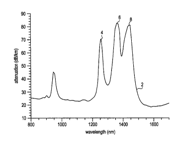
It is expected that the porous clad PCF will be susceptible to OH'
contamination because at least a portion of the light carrying area of the
fiber
has a relatively large surface area open to atmosphere after the OH' removal
step. The OH' removal step, known in the art, usually includes treating the
heated preform with a reactive gas such as chlorine. An example of OH'
contamination is shown in curve 2 of Fig. 1. The overall attenuation is high,
being above about 20 dBlkm over the wavelength range 800 nm to 1600 nm.
In addition the OH' absorption peak 4 at 1250 nm, and, the local maxima 6 and
8, which characterize the broad OH' maximum from about 1390 nm to 1450
nm, are unacceptably high and essentially render the waveguide useless
except perhaps in very short length applications.
The endlessly single mode property is however of sufficient value to attract
workers to address the problem of PCF manufacture. Another incentive to
develop a reliable and reproducible process for the PCF is the possibility of
achieving unusual dispersion properties which can be used for example in
dispersion compensating 5ber. The dispersion compensating fiber
compensates the dispersion in an existing communication link, thereby
allowing operation of the link at a different wavelength. Another PCF
advantage is that the large contrast available between core and clad effective
CA 02355678 2001-06-19
3
index can be used to provide large effective area, thereby mitigating non-
linear
effects on transmitted signal integrity.
The present waveguide fiber and waveguide fiber preform disclosed and
described herein reduces the unsatisfactory OH- contamination and effectively
overcomes the problems in the prior art.
Definitions
- The effective refractive index of a two or more component glass object, such
as the layer in the PCF preform and PCF drawn therefrom, having a
matrix of a firs lass containing rods of a second glass, is defined as,
~~ jw4~~2dA
neff - I!1 - ~n matrix +f nrod ~- k 2 ~I~IZ dA
where ~' is the solution of the scalar wave equation, k is the wave vector, f
is
fraction of the field in the rods and nmatrix and nrod are the respective
indices of
the matrix and rod glass of the clad layer.
- The scalar wave equation for light propagating in the z direction is:
c'~~I'/ax2
+a'~I'lc'~r2 +((kn,)2 -(32] ~I' = 0, where (3 is the propagation constant, k
the wave
number and n~ the core refractive index.
- The effective V number is, Veff = 2nL/~.(nmatrix2 - neff2)'~2, where L is
the pitch of
the rod pattern and ~, is wavelength.
Summary of the Invention
The PCF disclosed and described herein is free of air filled pores in the clad
layer. The clad layer of the present fiber includes a matrix material and at
least
one additional material. The matrix material and the at least one additional
material each have a refractive index and the respective refractive indexes
are
different from each other. The additional material is embedded in the matrix
material. The volume and spacing of the embedded material is adjusted to
provide a waveguide fiber having a wavelength range of single mode operation
that is large without bound. That is the waveguide is endlessly single mode.
Because both the matrix material and the at least one additional
material must transmit light in a pre-selected wavelength range, glass
materials
a~i ~~'~fi~~ S~ ~~
CA 02355678 2001-06-19
WO 00/37974 PCT/US99/28412
4
Because both the matrix material and the at least one additional
material must transmit light in a pre-selected wavelength range, glass
materials
are good choices. The refractive indexes of the glasses can be raised or
lowered by using appropriate dopant materials.
Thus the waveguide fiber preform and the fiber drawn therefrom meets the
need for a PCF fiber which has uniform and reproducible performance,
especially with regard to low spectral attenuation and geometry control.
A first aspect of the invention is an optical waveguide fiber preform
having a core body surrounded by a clad layer made up of a plurality of clad
rods. The clad rods each have a central portion, and a layer surrounding the
central portion. The central portion of the clad rods has a refractive index
different, by a pre-selected amount, from the refractive index of the
surrounding layer. This refractive index difference together with the relative
dimensions of the central portion and surrounding layer determine the
effective
refractive index of the clad layer and so affect fiber properties, for
example,
mode field diameter, cut off wavelength, zero dispersion wavelength, and
effective area. The effective index of the clad layer must be lower than the
core body refractive index in order for the assembly to ultimately become a
light guiding structure. The clad rod diameters are selected to provide a
final
light guiding structure that is free of porosity. A maximum cross sectional
dimension of the clad rods, in the preform, in the range of about 1.5 mm to
3.0
mm provides for a porosity free PCF after the preform is drawn to target fiber
dimensions.
An assembly of the clad rods and core body may be held together by
inserting it into holder such as a glass tube. One embodiment of the invention
employs a glass tube and has a refractive index lower than that of either the
central portion or the surrounding layer of the clad rod. As an alternative,
the
assembly can be bundled by using a frit to weld the preform parts together or
by heating the adjoining parts to cause them to adhere to one another. An
optically transparent adhesive may be used in place of the frit. Another
alternative is to clamp the ends of the preform assembly in proper alignment
and deposit a layer of glass soot on the assembly. Depending primarily upon
CA 02355678 2001-06-19
WO 00/37974 PCTNS99/28412
the soot density or cohesive strength, the soot may be sintered to form a
glass
before or during the drawing of the preform.
The core body can be a solid, rod-shaped glass object. Alternatively,
the core body can itself be composed of a group of individual rods. These
5 individual rods forming the core body may all have substantially the same
composition as one another or one or more pre-selected number of individual
rods may have different compositions. The choice of compositions of the
individual rods provides for certain optical characteristics of the fiber. For
example, one could use a group of up-doped silica rods to form a central
portion of the core body. A second group of pure silica rods could be arranged
as a first layer around the central up-doped portion of the core body, and a
third group of up-doped silica rods could be used to form a layer around the
first layer. This configuration of individual rods forming the core-body,
results in
a fiber whose core has a segmented refractive index profile after drawing the
preform to waveguide fiber dimensions. A core body having a segmented
refractive index profile can also be made in a separate process, such as, the
outside or inside vapor deposition processes which are well known to those
skilled in the art, and the core body so made inserted into the preform
assembly.
Similarly, in another embodiment, the core body can be constructed to
provide a graded index, i.e., a refractive index which varies in accord with a
function relating that index to the radial position.
The preform structure provides essentially a limitless number of
alternative configurations. The composition and arrangement of the individual
rods forming the core body can be varied. So too the composition and
arrangement of the clad rods forming the clad layer can be varied. Different
combinations of core body and clad layer can then provide a preform assembly
that can be used to provide numerous diverse preform structures that result in
corresponding waveguide fibers having diverse functional properties. The only
significant limitations on the useful rod configurations are as follows. The
effective refractive index of the clad must be lower than the effective index
of at
least a portion of the core so that the structure will guide light. In
addition, the
CA 02355678 2001-06-19
WO 00/37974 PCT/US99/28412
6
weight-percent dopant must be consistent or competitive with low attenuation
waveguide fibers. Also, the refractive index profile of core body and clad
layer,
which is determined by the composition and stacking pattern of the rods, is
selected to provide a fiber having desired characteristics such as large
effective area, low dispersion or dispersion slope, and, properly placed cut
off
or zero dispersion wavelengths. Finally, it is also favorable for the contrast
of
refractive index between the core body and clad layer indexes to be large
within practical limits in order to minimize bend sensitivity of the fiber.
In further embodiments of the preform and fiber, the clad rods forming
the clad layer can be made to have essentially any cross-sectional shape, such
as a circle, ellipse, triangle, parallelogram, or polygon. Different clad rod
shapes provide for different distributions, in the clad layer, of the clad rod
central portion and the clad rod surrounding layer, thereby affecting the
effective refractive index. It will be recalled that the effective refractive
index of
the clad layer depends upon the relative volume and distribution of the
materials of the central portion and the surrounding layer of the clad rods.
One
particular embodiment has clad rods of circular cross section overall and a
circular central region. In this case, the ratio of the diameter of the
central clad
rod portion to the outside diameter of the clad rod is preferably in the range
of
about 0.1 to 0.4, to provide a preform for the drawing of endlessly single
mode
waveguide fiber. However, using the PCF in a few-mode or multimode
configuration is contemplated, so that useful ratios of central portion of
clad rod
diameter to overall clad rod diameter may provide a useful waveguide structure
at values that range upward to 0.9 or higher. The circular clad rod embodiment
can be arranged in a number of different patterns, such as a hexagonal close
pack, a body-centered cubic structure, or a random structure. The random
structure may be achieved through randomly placed spacer rods having a
constant- or graded-index profile.
In addition, the clad rods may be arranged to form an asymmetric
pattern such as is found in polarization-maintaining waveguide fiber. Groups
of
rods arranged in an asymmetric, random, or periodic pattern can further be
CA 02355678 2001-06-19
WO 00/37974 PCT/US99/28412
7
grouped to form a larger independent pattern that is asymmetric, random, or
periodic. Mirror and rotational symmetries can also be fabricated.
Thus, in one embodiment of the invention, the individual rods forming
the core body or the clad rods forming the surrounding clad layer may be
selected to provide a preform from which a polarization-maintaining fiber can
be drawn. For example, the assembly of individual rods of the core body could
be chosen such that the final shape of the core region, that is the drawn form
of the core body, is elliptical. A number of different arrangements of
individual
rods forming the core body or clad rods forming the surrounding clad layer can
similarly provide a preform having a predetermined birefringence
characteristic,
from which a waveguide fiber having desired birefringence can be drawn.
Variations of the preform embodiments that feature clad rods of different
cross section may be achieved by changing the cross sectional shape of the
core body or the individual rods forming the core body. The core body or
individual rods forming the core body may take on any of the shapes set forth
above with respect to the clad rods.
In an embodiment of the preform in which the core body is a single rod
of circular cross section (to be used in a preform comprising circular clad
rods)
one preferred range for the core body diameter is about 1.5 mm to 3 mm. In
another embodiment having circular cross sections of the core body and the
clad rods of the clad layer, the core body diameter is about equal to that of
the
clad rods of the clad layer.
The characteristics of the preform, and thus of the fiber drawn
therefrom, may also be selectively changed by filling in some or all of the
interstitial voids which may be present in the preform assembly. Glass rods or
glass-forming material in granular or powder form may be used for this
purpose.
In yet another embodiment of the preform, the clad rods may include a
material to enhance the photosensitivity of the glass, and the properties of
the
fiber drawn from the preform may then be more readily modified by irradiation.
Materials such as germanium, antimony or boron are suitable.
CA 02355678 2001-06-19
WO 00/37974 PCT/US99/28412
8
The assembled preform therefore permits a great deal of flexibility in
terms of fiber properties themselves, and how and when these properties may
be altered.
Another example of this flexibility is an embodiment in which the clad
rods contain a dopant material at a weight percentage sufficient to induce
stress birefringence. The induced stresses can exist at the interface between
the core body and clad rod layer, or at the interface between the central
portion
and the surrounding portion of each clad rod. Dopant levels of germania in the
silica- based glass at a weight percentage in the range of about 30% to 50%
are considered effective to induce the desired stress birefringence. Also
considered effective is boron oxide doped into the silica-based glass at a
weight percentage in the range of about 10% to 20%. Depending on clad rod
arrangement, the resulting PCF can maintain an existing polarization state, or
can reduce effects such as polarization mode dispersion by means of
polarization mode mixing.
The waveguide fiber drawn from the preform, including its representative
embodiments described herein, will have a clad layer which includes a matrix
glass having glass columns embedded therein, in which the refractive index of
the columns is lower than that of the matrix glass. It will be readily
understood
that the matrix glass corresponds to the surrounding layers of the clad rods
and
that the columns correspond to the central portions of the clad rods.
The core portion of the waveguide fiber may have a step index (resulting
from using a single core rod of uniform composition) or a segmented refractive
index profile design. The segmented index can be incorporated into a single
core rod used in the preform assembly. The segmented index may also be
formed using a plurality of core rods that make up the core body of the
preform
assembly.
The glass columns embedded in the clad layer of the waveguide may
form a geometrically uniform, random, asymmetric, or periodic array. In a
periodic array of silica glass columns embedded in a matrix glass of higher
index, the pitch, that is, the spacing between column centers, may be in the
CA 02355678 2001-06-19
WO 00/37974 PCT/US99/28412
9
range of about 0.4 pm to 40 pm. An asymmetry may be chosen to produce
birefringence as is discussed above.
In one embodiment of the waveguide fiber, the relative refractive index
difference between the column and matrix giass, as well as the shape and
relative size of the glass columns are selected to provide single mode
operation over a wide, essentially limitless, wavelength range. This is the
endlessly single mode condition described and defined above. The range of
optical transparency of glass materials is of particular interest in the field
of
telecommunications. The entire available range spans about 200 nm to 1700
nm, but there are currently two operating windows of greatest interest: a
first
window centered at about 1300 nm, and a second centered at about 1550 nm.
In one embodiment of the waveguide fiber, the columns have a circular
cross-section of diameter in the range of about 1 pm to 35 p.m.
Brief Description of the Drawings
Fig. 1 is a spectral attenuation chart of a prior art fiber;
Figs. 2 is a chart of effective V number versus inverse wavelength for
several choices of the ratio of column diameter to pitch of this invention;
Fig. 3A is a cross section view illustrating a preform of this invention;
Fig. 3B is a side view of the preform of this invention or fiber drawn
therefrom;
Fig. 4 shows the definition of diameter and pitch in the preform or fiber;
Fig. 5 shows alternative rod shapes for the core or clad rods;
Fig. 6 illustrates a segmented core design in which the core has three
segments;
Fig. 7A illustrates a hexagonal close pack clad rod layer;
Fig. 7B illustrates a body centered cubic clad rod layer;
Fig. 8 illustrates one reduction to practice of a preform configuration,
having a core body composed of a single uniform rod surrounded by a layer of
circular clad rods; and,
Fig. 9 is an end view of a waveguide fiber drawn from the preform of Fig.
8.
CA 02355678 2001-06-19
WO 00/37974 PCT/US99/28412
Detailed Description of the Invention
The light guiding principle of the non-porous clad PCF, disclosed and
described herein, derives from the properties of its clad layer which is made
up
of two or more component materials. In such a clad layer an effective
5 refractive index can be defined which is a combination of the refractive
indexes
of the component materials. The dependence of the effective refractive index
on the refractive indexes of the clad layer components is expressed in terms
of
the ratio of the component material volume to the overall clad volume.
The value of the effective refractive index of the clad layer and the
10 refractive index of the core body determine how the light power is
distributed
across the core body and a portion of the clad layer adjacent to the core
body.
As is well known by those skilled in the art, the light power distribution in
the waveguide determines essentially all the optical properties of the
waveguide.
The clad layer of the PCF is made up of clad rods distributed around a
core body to form a preform that is an assembly of the rods. This assembly is
then drawn into a PCF. The use of sub-components, clad rods or individual
rods that make up the core body, permits a great deal of flexibility in
setting the
parameters of the PCF.
In the PCF discussed herein, the clad layer such as 58 in Fig. 8 provides
for an effective refractive index because the clad layer 58 has two components
possessing different refractive indexes.
A cross-sectional view of a first embodiment of the preform 18 is shown
in Fig. 3A. In this example, clad rods 10 have a central portion 12 that
possesses a lower refractive index than the surrounding layer 22. The clad
rods 10 have a circular cross section and all are substantially identical to
each
other. The clad rods 12 are arranged around the core body 14 to form an
assembly comprising the clad rods and the core body. The rods 16 shown
within the core body 14 indicate that the core body optionally can be made up
of smaller sub-units, that is individual rods. In the case shown, the assembly
components 10 and 14 are held in registration with one another by tube 18.
The assembly can also be bundled using any of several clamping, chucking,
CA 02355678 2001-06-19
WO 00/37974 PCT/US99~Z8412
11
wrapping, or other holding means known in the art. In addition a glass frit
can
be used to solder the components together. Also the components may be
bundled temporarily while the assembly is heated to a temperature which
causes the components to adhere to each other. The optional use of glass
filler rods or granular glass forming particles to fill the interstices of the
assembly is indicated by the series of dots and small circles 20.
A side view of the preform or waveguide 18 (the figure is illustrative of
both the preform and the waveguide drawn therefrom) is illustrated in Fig. 3B.
The core body 14 and the representative clad rod are shown extending from
one end to the other of the preform or fiber 24. Although core body 14 must
extend from end to end of the fiber or preform to make the structure function
as
a waveguide, the clad rods 12 may be discontinuous as long as the effective
refractive index of the clad is lower than that of at least a portion of the
core
body along substantially the full extent of the preform or waveguide.
The two clad rods 14 in Fig. 4 illustrate the definitions of column
diameter and pitch of the clad rod array. The column diameter 28 is shown as
a side to side dimension of column body 12. The pitch 26 is the linear
distance
between corresponding points on the central portions of clad rods 14. These
definitions pertain to both the preform assembly clad layer and the waveguide
fiber clad layer.
Alternative embodiments of the clad rods are shown in Fig. 5. Three of
the many useful shapes are shown as triangle 30, hexagon 32 and rectangle
34. In each embodiment, the central portion of the clad rod is shown as a
circular region 12. However, it will be understood that the shape of the
central
portion may be changed because it is convenient to do so or because a
desired PCF property is achieved thereby. The shapes of Fig. 5 may also
represent alternative core body shapes. Such shape changes are
contemplated as providing particular mode power distributions, which in turn
determine the key functional properties of the PCF waveguide.
Yet another embodiment of the core body is shown in Fig. 6. In this
case, the core rod is a segmented core design having a central segment, 36,
and respective first and second annular segments 38 and 40. The choice of
CA 02355678 2001-06-19
WO 00/37974 PCT/US99/28412
12
shape, radius and relative refractive index of the segments 36, 38, and 40
determine the functional properties of the waveguide containing the segmented
core. The segmented core principle and properties are discussed in several
publications and patents, for example, U. S. patent 5,748,824, Smith,
incorporated herein by reference, and so will not be discussed further.
The embodiment in which the clad rods are cylindrical in shape can also
provide for different waveguide function if the rods are arranged in pre-
selected
patterns, two of which are illustrated in Figs. 7A & 7B. The hexagonal
stacking
pattern is shown as assembly 42 in Fig. 7A and the body-centered cubic
pattern is shown as assembly 44 in Fig. 7B. This last pattern may also be
called a face centered cubic structure without loss of clarity of meaning.
The cylindrical clad rod embodiment has been investigated further using
a computer model to calculate key waveguide fiber properties. The properties
so calculated are shown as the curves 46, 48, 50, 52, and 54 of Fig. 2 . These
curves are discussed further below.
Example 1
Referring to Fig. 8, a preform 52 was constructed by inserting clad rods
48 and core rod 50 into tube 46. The clad rods 48 were placed in a periodic
array about the core rod 50. The outer diameter of the core rod and the clad
rods was about 2.4 mm. The diameter of the central portion of the clad rods,
54, was about 0.95 mm. The pitch 56 of the periodic array was about 2.4 mm.
The outside diameter of the preform was about 50 mm.
The clad rods comprised a silica core portion 58 and a clad layer 60 of
silica containing titania and having a 0% of about1 %, where
D% = 100 x (n~ - n2)/n~.
The refractive index denoted n~ is that of the glass region having the ~
value and n2 is a reference refractive index usually taken as the refractive
index of the base glass, which in this case is silica.
CA 02355678 2001-06-19
WO 00/37974 PCT/US99/28412
13
The preform was drawn into a PCF waveguide as illustrated in Fig. 9,
which is derived from an end photograph of the fiber.
Example 2
A PCF waveguide 24 having cylindrical clad rods 22 in Fig. 3A or 49 in
Fig. 8, and cylindrical clad rod central portions 12 or 58 is modeled assuming
a
clad rod surrounding layer relative index of 2%. The relative index % of a
structure is defined as 0% _ (n~ - nz)/ni, where n, is the maximum refractive
index of the glass region under consideration and n2 is a reference index, in
this example taken to be that of silica. When the preform using these clad
rods
is drawn info a waveguide fiber, the surrounding clad glass layer becomes the
matrix glass of the fiber clad and the central portion of the clad rods
becomes
the glass columns embedded in the matrix. The glass columns in this example
are chosen to be silica.
The clad rods are assembled about the core body to form a periodic
array having pitch L, for example 56 is Fig. 8. The diameter of.the glass
columns is denoted d. The Vex, which is descriptive of the number of modes
the waveguide can support, is calculated for several values of the ratio d/L
as
measured in the fiber drawn from the preform.
The chart of Fig. 2 shows Vex as a function of inverse light wavelength
scaled by the pitch of the array, L/~.. Curves 46 and 48 show that for d/L
ratios
of 0.2 and 0.4, the associated V numbers approach about 2.5 and 4
respectively as the wavelength decreases. Because the second mode of the
example waveguide fiber cuts off at V of about 4, curves 46 and 48 show the
waveguide to be single mode at essentially all wavelengths. This is the
endlessly single mode condition. The geometry of the waveguide fiber is
reasonable in that the pitch is of the order of several microns, about 1.5 pm
to
39 Vim, at an operating wavelength of 1550 nm. The column diameter follows
the pitch and at the 1550 nm wavelength is in the range of about 1.4 pm to 36
hem. As the ratio of d/L increases to 0.6, 0.8, and 0.9, the Veff dependence
changes as shown in curves 50, 52, and 54. The range of wavelengths for
which the waveguide is single mode is reduced, which makes the choice of
ratio a tradeoff with waveguide fiber performance. For example assuming a
CA 02355678 2001-06-19
WO 00/37974 PG"T/US99/28412
14
pitch of 10 ~,m, and a column diameter of 9 ~.m, the second mode cut off is
about 4 pm, which is above the preferred operating range for
telecommunication systems.
However, at a pitch of 10 ~,m, a column diameter of about 6 ~m provides
for single mode operation over the range 1530 nm to 1570 nm. In terms of Fig.
2, given the 10 ~m pitch and the operating wavelength range, one possibility
would be to design the clad in accord with curve 50. To reach the endlessly
single mode condition, the design could follow curve 48, which calls for a
column diameter of 4 wm.
This example illustrates the practicality of the non-porous PCF
waveguide fiber in the endlessly single mode configuration. It will be
understood that the preform and PCF drawn therefrom are not limited to the
endlessly single mode configuration.
The need for pressure control in the preform during the draw step, an
operation that is quite complex in terms of the control mechanism required, is
obviated.
The principle PCF control step is moved to an earlier and less complex
step in the process, i.e., the step in which the clad rod is fabricated.
Thus the control step occurs at a point in the process where control is
easier and less cost has been incurred.
As is known in the art, the light transmission through a guiding structure
is governed by Maxwell's equations. In the present case, the equations are
written to include the dielectric nature of the material of which the
waveguide is
made and the structure of the clad layer, including the size and disposition
of
the clad rods.
The following discussion shows that the waveguide fiber and preform
disclosed and described herein have properties which derive from Maxwell's
equations (ME).
The V number which results from applying the ME to the present PCF
determines the wavelength range over which the waveguide wilt transmit a
certain number of modes. Of particular interest is the V number below which
the waveguide transmits a single mode.
CA 02355678 2001-06-19
WO 00/37974 PCT/US99/28412
In terms of structure of the waveguide described herein, the effective V
number is defined as Veff = 2nL/~.(nmatrix2 - nerr2)"2 where L is the pitch of
the
columns contained in the clad layer, and ~, the propagated light wavelength.
To find the Vex at which the waveguide becomes endlessly single mode, one
5 charts Vefffor very large values of the ratio of column pitch transmitted
wavelength. That is, the limit of Veff is found as U~, -~ ~o. If Veff
approaches a
constant value in the limit as the ratio LI~, becomes large, Vex is
independent of
the transmitted light wavelength. The phenomenon of Vex becoming
independent of propagated light wavelength is the defining characteristic of
an
10 endlessly single mode fiber. This effect stems from the dependence of Veff
on
the field ~Y, and cannot be explained by simply asserting that the field power
is
moving into or out of either the column or matrix portions of the clad layer.
An alternative approach to defining the appropriate Vex which provides
an endlessly single mode condition is as follows. The effective refractive
index
15 of a two or more component glass object, such as the clad layer in the
preform
(and waveguide drawn therefrom) is defined as the propagation constant of the
fundamental space-filling light mode divided by the vacuum wave number, or
neff-~FSM~k~ The propagation constant ~i is found from the ME solutions and k
is 11~,, where ~, is the wavelength of the transmitted light. The ME are
solved
assuming that the outermost portion of the clad layer does not carry light.
The
fundamental space-filling mode (FSM) is the fundamental mode of the PCF if
the core body was removed from the fiber. Therefore (3FSM is the maximum
propagation constant ~i allowed in the cladding. An effective waveguide V-
number Veff=(2nLl~,) (not-ne~2)~n can also be defined. Here L is the pitch, ~,
the
wavelength, no the core index, and nee the effective index of the PCF clad
defined above. For the Vex below a threshold value the fiber remains single-
mode as can be seen in Fig. 2. The neff and Veff can be calculated from full
solutions to the ME, which are solved for the particular PCF geometry being
considered. The results of such calculations are shown in Fig. 2. To simplify
the calculation (carried out using a computer) the neff and Vex can be
approximated and their limiting behavior analyzed using the scalar wave
equation set forth below. It is seen in Fig. 2 that the chart of Veff vs. L/~,
CA 02355678 2001-06-19
WO 00/37974 PCT/LTS99/28412
16
flattens out at shorter wavelengths (large L/~,) and can be made to stay below
the cutoff value of about 4.1 for all wavelengths.
Thus one may reason as follows. In the short wavelength limit; the FSM
will hardly penetrate into the low index portions of the clad layer. Because
the
field will only be non-zero in the higher index (e.g. germania/silica) clad
layer
portions, the field is effectively confined to a clad region of constant
index.
Thus the mathematical expression for the held is a universal function of
normalized coordinates, independent of wavelength or the index in the PCF
columns, but which depends upon the pitch (center to center spacing) of the
clad structure.
The mathematical expression for the field will have the form,
~Y = G(x/L,y/L,).
When this function is substituted into the scalar wave equation
t~'Y/c~xz +a2'I'/c~y2 +I(kno)2 -X21 't' = 0
one ends neff2=not-gZ/(k2L2), where g is given by the solution of the wave
equation. Thus Vex = g = constant in the limit of small wavelength so that the
waveguide will remain single mode in the low wavelength limit.
This reasoning is set forth in support of the function of the PCF
described and disclosed herein. A reasonable explanation of the phenomena
is based upon sound physical principles. It will be understood that the
validity
of either of these interpretations of the effective V number and effective
refractive index in no way affects the scope or validity of the invention
described herein.
Although various embodiments of the invention have been disclosed
and described herein, the invention is nonetheless limited only by the
following
claims.