Note: Descriptions are shown in the official language in which they were submitted.
CA 02355929 2001-06-15
WO 00/35403 PCT/US99/30061
1
ORAL IRRIGATOR HOUSING
Field Of The Invention
This invention relates to oral irrigator housings, and more
particularly relates to oral irrigator housings that are keyed to maintain
s proper orientation between the base and reservoir, and provide
protection of the hand piece.
This application is related to co-pending application entitled "Oral
Irrigator Handle Assembly Having a Pressure Control Valve and Stop
Valve Assembly," Attorney Docket Number 16284.830026.000, Serial
to Number 09/217,972, filed concurrently herewith, and assigned to the
assignee of this application, the disclosure of which is hereby
incorporated by reference in its entirety.
Background Of The Invention
Oral irrigators are very popular dental hygiene apparatus for use
is in maintaining healthy gums. Typically, however, oral irrigators are
relatively bulky and thus difficult set down for use. Since oral irrigators
are often used in bathrooms, and typically bathrooms have little or no
counter top space, their size makes them sometimes hard to use.
Their size also makes oral irrigators difficult to store when not in use.
2o Where an oral irrigator includes a removable reservoir for easy
filling, these reservoirs are difficult to reposition properly on the base
since the reservoir and the base have to be properly engaged to insure
the fluid communication from the reservoir to the base is fluid-tight and
does not leak. It is sometimes very difficult to reposition the reservoir
2s without any guide or positional guidance.
Further, when the hand piece is stored in the base it is often
subject to inadvertent contact which can dislodge or damage the hand
CA 02355929 2001-06-15
WO 00/35403 PC'T/US99/30061
2
piece. Typical oral irrigators allow the hand piece to be stored upright
next to the reservoir, but in this position the hand piece is exposed
from all but one side to inadvertent and potentially damaging contact by
the user.
s What is needed in the art is an oral irrigator housing that has a
positional orientation structure to make attachment of the separable
reservoir to the base more easily accomplished. In addition, an oral
irrigator housing that forms a protective envelope around the hand
piece while stored upright on the base is needed.
to Summary Of The Invention
The oral irrigator housing of the present invention was developed
with the shortcomings of the available housings described above in
mind. The present invention provides an oral irrigator with an improved
reservoir placement guide to facilitate easier and more accurate
is positioning of the reservoir on the top of the base unit in the upright
position. In addition, the reservoir in the upright position acts to protect
the stored hand piece by surrounding the hand piece in an indentation
in the reservoir. The reservoir is also useable as a cover to protect the
handle and jet tips, and to allow the oral irrigator to be stored more
Zo easily.
In more detail, a housing for an oral irrigator having a hand piece
includes a base unit having an upper and lower portion, the lower
portion engageable with a support surface and having an upper surface
defining a recess for receiving the hand piece, and the lower portion
2s defining a peripheral shoulder. The upper portion extends upwardly
from the lower portion and defines a top surface, the top surface
defining a port, the upper portion being positioned inside the peripheral
shoulder. A reservoir has a bottom surface defining an aperture and
sidewalis extending upwardly from the bottom surface to define a cavity
CA 02355929 2001-06-15
WO 00/35403 PCT/US99/30061
3
having a peripheral rim, the sidewalls in part defining an indentation
extending from the bottom surface up to a top end adjacent the
peripheral rim at a position interior to the peripheral rim. A top wall
extends from the top end of the indentation to the peripheral rim, the
s top wall forming an overhang.
The reservoir is positionable on the base unit such that the
peripheral rim engages the peripheral shoulder on the housing unit to
encompass the upper portion of the motor housing unit in the cavity.
The reservoir is also positionable on the base unit such that the bottom
io surface of the reservoir rests on the top surface of the upper portion
with the port and the aperture in alignment and sealingly engaged. The
indentation is oriented with the recess, wherein the hand piece is
received in the indentation and covered by the top wall.
In addition, the housing can further include a key extending
is upwardly from the top surface of the base unit, with the bottom surface
of the reservoir defining a recess having a complimentary shape to the
key. The key is received in the recess when the reservoir is positioned
on the base unit such that the bottom surface of the reservoir rests on
the top surface of the upper portion with the port and the aperture in
2o alignment and sealingly engaged.
A more complete appreciation of the present invention and its
scope can be obtained from understanding the accompanying
drawings, which are briefly summarized below, the following detailed
description of the presently preferred embodiments of the invention,
2s and the appended claims.
Brief Description Of The Drawings
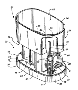
Fig. 1 is a perspective view of the oral irrigator housing
incorporating the present invention showing the reservoir in the upright
CA 02355929 2001-06-15
WO 00/35403 PCTNS99/30061
4
position on the base unit, and the hand piece positioned in the
indentation formed in the reservoir.
Fig. 2-3 are together an exploded perspective view of the oral
irrigator housing of Fig. 1.
s Fig. 4 is a perspective view of the oral irrigator housing of Fig. 1
with the reservoir in the cover position.
Fig. 5 is a perspective view of the oral irrigator showing the hand
piece removed from its storage recess on the base unit.
Fig. 6 is a side view of the oral irrigator with the reservoir in the
to upright position, and the hand piece positioned in the indentation.
Fig. 7 is an exploded view of the oral irrigator housing showing a
medicament reservoir and cover.
Fig. 8 is a bottom perspective view of the medicament reservoir.
Detailed Description Of The Preferred Embodiment
is The oral irrigator housing 20 incorporating the present invention
is shown in Fig. 1. The housing 20 includes a base unit 22 and a
reservoir 24 for either holding water to supply the base unit 22 or
covering the base unit 22. A hand piece 26 is attached by a tube 28 to
the base unit 22, and is used to direct a pulsated water stream. The
20 oral irrigator is used as a part of proper dental hygiene practice.
As best shown in Figs. 1 and 3, the base unit 22 has a lower
portion 30 and an upper portion 32, with the upper portion 32 extending
upwardly from the lower portion 30 and leaving an exposed upper
surface 34. The lower portion 30 has a bottom 36 for resting on a
2s support surface, such as a table, sink or dresser. The upper
surface 34 defines a recess 38 (see Fig. 5) having a rectangular
CA 02355929 2001-06-15
WO 00/35403 PCT/US99/30061
perimeter 40 and a curved bottom 42 for storing the tube 28 in coiled
form. In addition, the upper surface 34 includes a substantially circular
recess 44 for receiving the handle 46 of the hand piece 26 and holding
it in an upright position adjacent to the upper portion 32 of the base
s unit 22. The upper surface 34 also defines at least one recess 48 for
receiving the base 50 of the jet tip portion 52 of the hand piece 26.
The lower portion 30 of the base unit 22 also includes a lower skirt 54
which defines a continuous peripheral shoulder 56 at its top edge 58, at
the intersection of the peripheral skirt 54 and the upper surface 34 of
to the lower portion 30.
The upper portion 32 of the base unit 22 extends upwardly from
the upper surface 34 of the lower portion 30 and is contained within the
peripheral shoulder 56. The upper portion 32 has curved, substantially
vertical side walls 60 and a top surface 62. The top surface 62 is
is relatively planar, and defines a portal 64 formed therein. A keyed
protrusion 66 is formed in the top surface 62 and extends from one end
of the top surface 62 toward the opposite end along the length
dimension of the upper portion 32. The keyed protrusion 66 has a first
flat wide end 68 adjacent the end of the top surface 62, and a second
ao curved narrow end 70 opposite the first end 68. The width between the
first and second ends preferably widens slightly in the middle and then
narrows to the curved second end tip 70.
The base unit 22 houses a motor and pump for providing a
pulsated stream of water to the hand piece 26. A suitable pump and
2s motor is disclosed in U.S. Patent No. 4,989,590, entitled "Irrigation
Appliance", issued February 5, 1991, and assigned to the assignee of
the present application, which is hereby incorporated by reference in its
entirety, or in U.S. Patent No. 5,399,089, entitled "Oral Hygiene
Appliance", issued March 21, 1995, and assigned to the assignee of
3o the present application, which is also incorporated by reference herein
CA 02355929 2001-06-15
WO 00/35403 PCT/US99/30061
6
in its entirety. The pump receives water from the fluid stored in the
reservoir 24, as described in more detail below. The motor is powered
by line voltage, connected through an outlet cord 72 and plug 74 to a
standard electric outlet.
s The tube 28 is attached to the output of the pump and carries the
pulsed fluid to the hand piece 26. The hand piece 26 includes a
handle 46 and a separable jet tip 52, and is used to direct the pulsed
fluid in the desired direction. A suitable hand piece 26 is disclosed in
U.S. Patent No. 5,399,089, entitled "Oral Hygiene Appliance", issued
io March 21, 1995, and assigned to the assignee of the present
application, or in related application "Oral Irrigator Handle Assembly
Having a Pressure Control Valve and Stop Valve Assembly," Attorney
Docket Number 16284.830026.000, Serial Number XX/XXX,XXX, filed
concurrently herewith and assigned to the assignee in this application,
is both incorporated by reference herein in their entirety. The hand
piece 26 can be stored in the base unit 22 in the recess 44 formed in
the upper surface 34 of the lower portion 30. The hand piece 26 is
stored in an upright orientation adjacent to the upper portion 32 of the
base unit 22.
2o As best shown in Figs. 1, 2 and 4, the reservoir 24 has a bottom
surface 76 defining an aperture 80, and side walls 78 extending
upwardly from the bottom surface 76. The combination of the bottom
surface 76 and the side walls 78 form a cavity 82 having a peripheral
rim 84 defining an opening. The bottom surface 76 of the reservoir 24
2s also defines a recess 86 having the complimentary shape to the key
protrusion 66 formed on the top surface 34 of the upper portion 32 of
the base unit 22. The recess 86 extends from one end of the bottom
surface 76 toward the opposite end along the length dimension of the
reservoir 24. The recess 86 is formed at the intersection of the bottom
3o surface 76 and the side wall 78, and thus forms a recess in the side
CA 02355929 2001-06-15
WO 00/35403 PCT/US99/30061
7
wall 78. The keyed recess 86 has a first flat wide end 88 adjacent the
end of the bottom surface 76, and a second curved narrow end 90
opposite the first end 88. The width between the first and second ends
preferably widens slightly in the middle and then narrows to the curved
s second end tip 90. The reservoir 24 is preferably made of plastic, such
as ABS or high-impact poly-styrene.
The side walls 78 also define, at a corner of the reservoir 24, an
indentation 92 extending upwardly from the bottom surface 76 to a top
end 94 adjacent the peripheral rim 84. The indented area 92 extends
io inwardly from the peripheral rim 84. A top wall 96 extends from the top
end 94 of the indentation 92 to the peripheral rim 84, and forms an
overhang 98. The walls 100 of the indentation are preferably at right
angles to one another, with a rounded intersection between the walls.
The walls 100 of the indentation intersect the top wall 96 in a rounded
is corner.
The reservoir 24 is positionable on the base unit 22 in two
different orientations, upright and as a cover, each with its own
benefits. In the upright position, the bottom surface 76 of the
reservoir 24 contacts the upper surface 34 of the upper portion 32 of
2o the base 22. In the upright position, the reservoir 24 can hold water to
supply to the pump for passage through the hand piece 26 as desired.
To supply water to the pump, the aperture 80 formed in the bottom
surface 76 of the reservoir 24 orients with and sealingly engages the
portal 64 formed in the top surface 62 of the upper portion 32 of the
2s base unit 22. The structure allowing the aperture to sealingly engage
the portal 64 is any known or available structure, such as that disclosed
in U.S. Patent No. 5,399,089 referenced above.
The reservoir 24 is properly positioned on the base unit 22 by the
positioning of the key 66 on the top surface 62 of the upper portion 32
30 of the base unit 22 in the complimentarily-shaped recess 86 formed in
CA 02355929 2001-06-15
WO 00/35403 PCTNS99/30061
8
the bottom surface 76 of the reservoir 24, The elongated key 66 can
enter the end of the recess 86 as the reservoir 24 is moved lengthwise
over the base 22 to where the tip 70 of the key 66 engages the tip 90
of the recess 86. At this point the entire length of the key 66 is
positioned within the recess 86. The sidewalls of the key 66 engage
the sidewalls of the recess 86 to help maintain the proper lateral
positioning of the reservoir 24 on the top surface 62 of the base
unit 22. When the tip 70 of the key 66 engages the tip 90 of the
recess 86, the longitudinal positioning and lateral positioning of the
Io reservoir 24 is proper, and the aperture 80 and portal 64 are aligned for
sealing engagement. This guided engagement is easily initiated by the
user inserting the tip 70 of the key 66 into the open end 88 of the
recess 86, and moving the reservoir 24 longitudinally along the top of
the base unit 22 until the tip 70 of the key 66 and the tip 90 of the
is recess 86 engage.
This keyed orientation of the reservoir 24 and base unit 22 is
important for several reasons. One important reason is that the
reservoir 24 is typically mounted on the base 22 after being filled with
water. The key structure acts as a guide so the user does not have to
Zo guess the proper centered position of the reservoir 24 on the base
unit 22, and also does not have to estimate where the aperture 80 is
properly oriented with the portal 64.
After the reservoir 24 has been properly positioned, the user
actuates the motor and pump by the on-off slide switch on the base
2s unit 22. The pump draws water out of the reservoir 24 and pumps it
through the hand piece 26 until the reservoir 24 is empty.
Another benefit of the placement of the reservoir 24 in the
upright position on the base unit 22 is that it protects the hand piece 26
stored in the upright position in the base unit 22. The hand piece 26
so extends upwardly, as shown in Figs. 1 and 6 at a position to extend
CA 02355929 2001-06-15
WO 00/35403 PCTNS99/30061
9
into and be received by the indentation 92 in the reservoir 24. The top
wall 96 extends over the hand piece 26, and two adjacent
sidewalis 100 of the indentation 92 protect the hand piece from
incidental vertical or lateral contact by the user. This is a distinct
s advantage over other oral irrigators, where the hand piece is left
exposed to incidental contact and possible damage.
Once empty and the user has completed his or her use of the
oral irrigator, the reservoir 24 can be disengaged from the top of the
base unit 22 and inverted to be placed over the base unit 22, as shown
1o in Fig. 4. In this cover position, the jet tip 52 of the hand piece 26 must
be removed and stored in its particular storage location in the lower
portion 30 of the base unit 22, but the handle 46 of the hand piece 26
can remain in its particular recess 44. The peripheral rim 84 of the
reservoir 24 engages the peripheral shoulder 56 on the lower
1s portion 30 of the base unit 22 to orient the reservoir 24 and hold it in
place. The reservoir 24 in the cover position allows the oral irrigator to
have a reduced size for storage, and helps keep the handle 46 and jet
tips 52 from being dislodged, lost or damaged.
Figs. 7 and 8 show an alternative embodiment of the reservoir 24
2o for use on the base unit 22. This alternative reservoir 102 is smaller,
for use with smaller volumes of liquid, such as when medicament is to
be used in the oral irrigator. The bottom surface 104 of the
medicament reservoir 102 defines an aperture 106 identical to the
aperture above. The bottom surface 104 of the medicament
2s reservoir 102 also forms a recess 108 in the same spatial orientation to
the aperture as that described above. The recess 108 on the bottom
surface 104 of the medicament reservoir 102 is relatively short in
length and receives the tip 70 and a short length of the key 66 formed
on the top of the base unit 22. The majority of the length of the key 66
3o extends outside the recess. Nonetheless, the recess 108 works in
CA 02355929 2001-06-15
WO 00/35403 PCT/US99/30061
combination with the key 66 as a guide to properly position the
medicament reservoir 102 on the top surface 62 of the base unit 22 for
proper orientation of the aperture 106 with the portal 64. The
medicament reservoir 102 includes a top cover 110 having a ridge-type
handle 112 extending longitudinally along the top cover 110. The top
cover 110 is used to close the open end of the medicament reservoir if
desired.
in operation, the present invention provides an oral irrigator with
an improved reservoir placement guide to facilitate easier and more
to accurate positioning of the reservoir on the top of the base unit 22 in
the upright position. In addition, the reservoir in the upright position
acts to protect the stored hand piece by surrounding the hand piece in
an indentation in the reservoir. The reservoir is also useable as a
cover to protect the handle and jet tips, and to allow the oral irrigator to
Is be stored more easily.
A presently preferred embodiment of the present invention and
many of its improvements have been described with a degree of
particularity. It should be understood that this description has been
made by way of example, and that the invention is defined by the
2o scope of the following claims.