Language selection

Search

Patent 2356022 Summary

Third-party information liability

Some of the information on this Web page has been provided by external sources. The Government of Canada is not responsible for the accuracy, reliability or currency of the information supplied by external sources. Users wishing to rely upon this information should consult directly with the source of the information. Content provided by external sources is not subject to official languages, privacy and accessibility requirements.

Claims and Abstract availability

Any discrepancies in the text and image of the Claims and Abstract are due to differing posting times. Text of the Claims and Abstract are posted:

  • At the time the application is open to public inspection;
  • At the time of issue of the patent (grant).
(12) Patent: (11) CA 2356022
(54) English Title: TRIDEM AXLE SUSPENSION
(54) French Title: SUSPENSION D'ESSIEU TRIDEM
Status: Term Expired - Post Grant Beyond Limit
Bibliographic Data
(51) International Patent Classification (IPC):
  • B60G 5/00 (2006.01)
(72) Inventors :
  • SIMARD, ANDRE-MARIE (Canada)
  • LAVOIE, REJEAN (Canada)
(73) Owners :
  • EMMANUEL SIMARD & FILS (1983) INC.
(71) Applicants :
  • EMMANUEL SIMARD & FILS (1983) INC. (Canada)
(74) Agent: ROBIC AGENCE PI S.E.C./ROBIC IP AGENCY LP
(74) Associate agent:
(45) Issued: 2009-07-21
(22) Filed Date: 2001-08-29
(41) Open to Public Inspection: 2003-02-28
Examination requested: 2006-07-21
Availability of licence: N/A
Dedicated to the Public: N/A
(25) Language of filing: English

Patent Cooperation Treaty (PCT): No

(30) Application Priority Data: None

Abstracts

English Abstract

A tridem axle suspension for use in a vehicle having a front axle, a medium axle and a rear axle mounted in tridem relationship. It makes use of rigid beams to support the axles. It also makes use of equalizers to interconnect the beams, and it is devised in such a manner that one end of each beam is free to slide within the adjacent supporting structure. This suspension is very simple in structure and very efficient to equalize the load of any axle over all the axles of the tridem. When the axles are motorized, the suspension is also efficient to balance the pulls exerted by the wheels supported by the axles.


French Abstract

Suspension d'essieu tridem pour utilisation dans un véhicule doté d'un essieu avant, d'un essieu médian et d'un essieu arrière montés en tridem. La suspension comprend des poutres rigides qui supportent les essieux, de même que des stabilisateurs servant à interconnecter les poutres. La suspension est conçue de façon à ce que l'une des extrémités de chaque poutre soit libre de glisser dans la structure de support adjacente. La structure de cette suspension est très simple et permet de répartir efficacement la charge d'un essieu particulier sur tous les essieux du tridem. Lorsqu'une force motrice est appliquée aux essieux, la suspension permet également de répartir efficacement les forces de traction exercées par les roues supportées par les essieux.

Claims

Note: Claims are shown in the official language in which they were submitted.

7
CLAIMS
1. A tridem axle suspension for use in a vehicle having a frame
below which a front axle, a medium axle and a rear axle are mounted in
tridem relationship, said suspension comprising, on each side of the
vehicle :
- a front axle supporting beam having a front end pivotably
connected to a first hanger projecting downwardly from the frame, and a
rear end;
- a first equalizer rockably mounted onto a second hanger
projecting downwardly from the frame, said first equalizer having a front
portion through which the rear end of the front axle supporting beam is
slidably mounted, and a rear portion;
- a medium axle supporting beam having a front end pivotably
connected to the rear portion of the first equalizer, and a rear end;
- a second equalizer rockably mounted onto a third hanger
projecting downwardly from the frame, said second equalizer having a front
portion through which the rear end of the medium axle supporting beam is
slidably mounted, and a rear portion; and
- a rear axle supporting beam having a front end pivotably
connected to the rear portion of the second equalizer, and a rear end
slidably mounted onto a fourth hanger projecting downwardly from the
frame.
2. The tridem axle suspension of claim 1, wherein the front
portions of the first and second equalizers and the fourth hanger each
comprise a roller under which the rear ends of the front, medium and rear
axle supporting beams extend and bear, said rollers facilitating sliding of
said rear ends when the supporting beams pivot and the first and second
equalizers are rocked.

8
3. The tridem axle suspension of claim 2, wherein the front
portions of the first and second equalizers and the fourth hanger each
comprise a locking pin extending below the corresponding roller to prevent
the rear ends of the front, medium and rear axle support beams from
moving down away from the corresponding rollers in the case of a jump.
4. The tridem axle suspension of claim 3, wherein
each of the front, medium and rear axle supporting beams is
substantially V-shaped;
the front, medium and rear axles are centrally fixed on top of
said front, medium and rear axle supporting beams; and
the rear ends of said front, medium and rear axle supporting
beams are curved so as to extend substantially horizontally.

Description

Note: Descriptions are shown in the official language in which they were submitted.


CA 02356022 2001-08-29
1
TRIDEM AXLE SUSPENSION
BACKGROUND OF THE INVENTION
a) Field of the invention
The present invention relates to a tridem axle suspension for use
in a vehicle having a frame below which a front axle, a medium axle and a
rear axle are mounted in tridem relationship.
b) Brief description of the prior art
Tridem axle suspensions for use to equalize the load over three
adjacent axles of large vehicles such as trucks or semi-trailers, are already
known. In support of this contention, reference can be made, by way of
non-restrictive examples, German patent No. 520,672 of 1931 and to U.S.
patent Nos. 2,032,721 of 1936; 2,821,408 of 1958; 3,219,360 of 1965;
3,762,487 of 1973 and 4,813,695 of 1989.
In such a suspension, it is of common practice to use equalizers
that are rockably mounted under the frame of the vehicle and connected to
springs supporting the axles in such a manner as to distribute unequal
loading of any axle to all the axles of the tridem, in particular when the
vehicle moves on an uneven road or trail or passes over a bump. Once
again, reference can be made to the above-mentioned patents.
In the fieid of vehicle suspensions, it is also known to use rigid
beams to support the axles of the vehicle, instead of using springs (see, for
example, U.S. patent No. 3,219,360 mentioned hereinabove). However, in
such a case, other means must be provided to absorb the up and down
motions of the axles when the vehicle is moving, and to equalize the load
over all of axles.
In the field of vehicle suspensions, it is further known to let at
least one of the ends of an axle supporting spring free to slide relative to a
3 0 supporting hanger in order to absorb the up and down motions of the axle
supported by this spring. In this connection, reference can be made to U.S.

CA 02356022 2001-08-29
2
patent Nos. 3,767,222 of 1973 and 4,486,029 of 1984.
However, so far, no one seems to have ever thought of
combining all these knowledges in a tridem axle suspension in order to
improve the efficiency and reliability of the same.
SUMMARY OF THE INVENTION
The object of the present invention is to provide a tridem axle
suspension for use in a vehicle, which suspension is very simple in
structure, very efficient to equalize the load over the three adjacent axles
of the vehicle and very reliable in use.
The tridem axle suspension according to the invention makes
use of rigid beams to support the axles. It also makes use of equalizers and
it is devised in such a manner that one end of each beam is free to slide
within the adjacent supporting equalizer or hanger.
As aforesaid, the tridem axle suspension according to the
invention is intended to be used in a vehicle having a frame below which
a front axle, a medium axle and a rear axle are mounted in tridem
relationship.
It basically comprises, on each side of the vehicle
- a front axle supporting beam having a front end pivotably
connected to a first hanger projecting downwardly from the frame, and a
rear end;
- a first equalizer rockably mounted onto a second hanger
projecting downwardly from the frame, the first equalizer having a front
portion through which the rear end of the front axle supporting beam is
slidably mounted, and a rear portion;
- a medium axle supporting beam having a front end pivotably
connected to the rear portion of the first equalizer, and a rear end;
- a second equalizer rockably mounted onto a third hanger
projecting downwardly from the frame, the second equalizer having a front
portion through which the rear end of the medium axle supporting beam is

CA 02356022 2001-08-29
3
slidably mounted, and a rear portion; and
- a rear axle supporting beam having a front end pivotably
connected to the rear portion of the second equalizer, and a rear end
slidably mounted onto a fourth hanger projecting downwardly from the
frame.
As it can be appreciated, this suspension is very simple in
structure. This suspension is also efficient to equalize the load of any axle
over all the axles of the tridem. When the axles are motorized, the
suspension according to the invention may further balance the pulls exerted
by the wheels supported by the axles between all of them.
The invention and its advantages will be better understood upon
reading the following non-restrictive description of a preferred embodiment
thereof, made with reference to the accompanying drawings.
BRIEF DESCRIPTION OF THE DRAWINGS
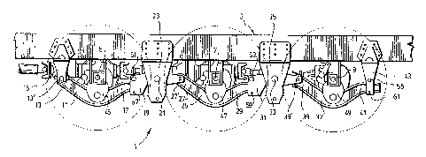
Fig. 1 is a side elevational view of a tridem axle suspension
according to a preferred embodiment of the invention, the suspension as it
is illustrated, being used in combination with a tridem drive axle system;
Fig. 2 is a side elevational view in partial cross-section of the rear
portion of the suspension shown in Fig. 1;
Fig. 3 is a view similar to the one of Fig. 1, but without the
tridem drive axle system; and
Fig. 4 is a view similar to the one of Fig. 3, when the front axle
passes over a bump.
DESCRIPTION OF A PREFERRED EMBODIMENT OF THE INVENTION
The tridem axle suspension 1 according to the preferred
embodiment of the invention as shown in the accompanying drawing is
intended to be used in a vehicle having a frame 3 below which a front axle
5, a medium axle 7 and a rear axle 9 are mounted in tridem relationship.
------------ -

CA 02356022 2001-08-29
4
The suspension 1 comprises a plurality of similar structural
elements on each side of the vehicle.
These elements include a front axle supporting beam 11 having
a front end 13 pivotably connected by means of an horizontal pin 13' to a
first hanger 15 projecting downwardly from the frame. The beam 11 also
has a rear end 17.
Also included is a first equalizer 19 rockably mounted by means
of an horizontal pin 21 onto a second hanger 23 projecting downwardly
from the frame. This first equalizer 19 has a front portion in which the rear
end 17 of the front axle supporting beam 11 is slidably mounted, and a rear
portion.
Further included is a medium axle supporting beam 25 having a
front end 27 pivotably connected by means of a pin 27' to the rear portion
of the first equalizer 19. This beam 25 also has a rear end 29.
Further included is a second equalizer 31 rockably mounted by
means of an horizontal pin 33 onto a third hanger 35 projecting downwardly
from the frame. This second equalizer 31 has a front portion in which the
rear end 29 of the medium axle supporting beam 25 is slidably mounted,
and a rear portion.
Last of all, the suspension includes as other structural element,
a rear axle supporting beam 37 having a front end 39 pivotably connected
to the rear portion of the second equalizer 31 by means of a pin 39', and
a rear end 41 slidably mounted onto a fourth hanger 43 projecting
downwardly from the frame 3.
In the illustrated preferred embodiment, the front, medium and
rear axle supporting beams 11, 25 and 37 are V-shaped and the front,
medium and rear axles 5, 7 and 9 are centrally fixed on top of them by
means of brackets 45, 47 and 49, respectively. However, the beams could
have a different shape and the axles could be connected thereto in a
different manner and/or by other means. Such is rather conventional and
need not be further described.

CA 02356022 2001-08-29
In the illustrated preferred embodiment, the rear ends 17, 29 and
41 of the front, medium and rear axle supporting beams 11, 25 and 37 are
also curved so as to extend substantially horizontally. Such is particularly
useful to facilitate free sliding mounting of the rear ends of the beams 11,
5 25 and 37 out the front portions of the first and second equalizers 19 and
31 and onto the fourth hanger 43, respectively.
As is better shown in Fig. 2, the front portions of the first and
second equalizers 19 and 31 and the fourth hanger 43 each preferably
comprises a roller 51, 53, 55 under which the rear ends 17, 29 and 41 of
the front, medium and rear axle supporting beams 11, 25 and 37 extend
and bear. The rollers 51, 53 and 55 facilitate the requested sliding of the
rear ends 17, 29 and 41 when the supporting beams 11, 25 and 37 pivot
and the first and second equalizers 19 and 31 are rocked (see Fig. 4). It is
worth noting however that means other than a roller could alternatively be
used for slidably mounting the rear end of each beam onto the adjacent
structure. By way of example, use could be made of a sleeve which would
be pivotably mounted to the structure and through which the rear end of the
corresponding beam could be free to slide. However, such would be
structurally more complicated than the use of a roller.
2 0 Even though such is not compulsory, the front portions of the
first and second equalizers 19 and 31 and the fourth hanger 43 may each
comprise a locking pin 57, 59, 61 extending below the corresponding roller
51, 53, 55 to prevent the rear ends 17, 29 and 41 of the front, medium and
rear axle support beams from moving down too far away from the
corresponding rollers in the case of a jump on the road or trail.
As it can be understood by comparing Fig. 3 with Fig. 4, the
suspension 1 according to the invention actually permits to equalize the load
over the three adjacent axles 5, 7 and 9 of the vehicles which is preferably
a large and "heavy" vehicle, like a truck or semi-trailer. This suspension is
3 0 very simple in structure. Tests carried out by the inventor have also
shown
that it is very efficient and reliable in use.

CA 02356022 2001-08-29
6
Moreover, the suspension 1 is "compatible" with conventional
tridem drive axle systems like the one illustrated in Fig. 1 or the one
disclosed in U.S. patent No. 4,977,972 of 1990. As a matter of fact, when
used with such a drive axle system, the suspension 1 according to the
invention permits to balance the pulls exerted by the wheels supported by
the axles between all of said wheels whatever be the shape and/or lateral
inclination of the road or trail on which the vehicle moves.
Of course, numerous modifications could be made to the
preferred embodiment disclosed hereinabove without departing from the
scope of the invention. By way of examples, the particular shape, structure
and assembly of the hanger 15, 23, 35 and 43 could be different from what
is illustrated, provided of course that they have the same function.
Similarly,
the shape of the beams 17, 29 and 37 could be different.

Representative Drawing
A single figure which represents the drawing illustrating the invention.
Administrative Status

2024-08-01:As part of the Next Generation Patents (NGP) transition, the Canadian Patents Database (CPD) now contains a more detailed Event History, which replicates the Event Log of our new back-office solution.

Please note that "Inactive:" events refers to events no longer in use in our new back-office solution.

For a clearer understanding of the status of the application/patent presented on this page, the site Disclaimer , as well as the definitions for Patent , Event History , Maintenance Fee  and Payment History  should be consulted.

Event History

Description Date
Inactive: Expired (new Act pat) 2021-08-30
Common Representative Appointed 2019-10-30
Change of Address or Method of Correspondence Request Received 2018-12-04
Letter Sent 2017-05-31
Inactive: Multiple transfers 2017-05-15
Maintenance Request Received 2014-08-15
Maintenance Request Received 2013-06-07
Inactive: Correspondence - MF 2010-08-10
Grant by Issuance 2009-07-21
Inactive: Cover page published 2009-07-20
Inactive: Final fee received 2009-04-23
Pre-grant 2009-04-23
Letter Sent 2009-03-30
Notice of Allowance is Issued 2009-03-30
Inactive: Approved for allowance (AFA) 2009-03-09
Letter Sent 2006-08-10
Request for Examination Requirements Determined Compliant 2006-07-21
All Requirements for Examination Determined Compliant 2006-07-21
Request for Examination Received 2006-07-21
Application Published (Open to Public Inspection) 2003-02-28
Inactive: Cover page published 2003-02-27
Inactive: First IPC assigned 2001-10-25
Inactive: Filing certificate - No RFE (English) 2001-09-13
Filing Requirements Determined Compliant 2001-09-13
Letter Sent 2001-09-13
Application Received - Regular National 2001-09-13

Abandonment History

There is no abandonment history.

Maintenance Fee

The last payment was received on 2009-05-14

Note : If the full payment has not been received on or before the date indicated, a further fee may be required which may be one of the following

  • the reinstatement fee;
  • the late payment fee; or
  • additional fee to reverse deemed expiry.

Please refer to the CIPO Patent Fees web page to see all current fee amounts.

Owners on Record

Note: Records showing the ownership history in alphabetical order.

Current Owners on Record
EMMANUEL SIMARD & FILS (1983) INC.
Past Owners on Record
ANDRE-MARIE SIMARD
REJEAN LAVOIE
Past Owners that do not appear in the "Owners on Record" listing will appear in other documentation within the application.
Documents

To view selected files, please enter reCAPTCHA code :


To view images, click a link in the Document Description column. To download the documents, select one or more checkboxes in the first column and then click the "Download Selected in PDF format (Zip Archive)" or the "Download Selected as Single PDF" button.

List of published and non-published patent-specific documents on the CPD .

If you have any difficulty accessing content, you can call the Client Service Centre at 1-866-997-1936 or send them an e-mail at CIPO Client Service Centre.


Document
Description 
Date
(yyyy-mm-dd) 
Number of pages   Size of Image (KB) 
Representative drawing 2002-03-11 1 18
Cover Page 2003-01-31 1 44
Drawings 2001-08-29 3 108
Claims 2001-08-29 2 61
Description 2001-08-29 6 269
Abstract 2001-08-29 1 17
Representative drawing 2009-06-22 1 18
Cover Page 2009-06-22 1 46
Courtesy - Certificate of registration (related document(s)) 2001-09-13 1 136
Filing Certificate (English) 2001-09-13 1 175
Reminder of maintenance fee due 2003-04-30 1 107
Reminder - Request for Examination 2006-05-02 1 125
Acknowledgement of Request for Examination 2006-08-10 1 177
Commissioner's Notice - Application Found Allowable 2009-03-30 1 163
Fees 2003-06-19 1 29
Fees 2004-06-29 1 29
Fees 2005-06-09 1 26
Fees 2006-06-22 1 31
Fees 2007-08-01 1 41
Fees 2008-07-15 1 42
Correspondence 2009-04-23 2 53
Fees 2009-05-14 1 53
Fees 2010-05-28 1 32
Correspondence 2010-08-10 1 46
Fees 2011-08-11 1 33
Fees 2012-07-26 1 37
Fees 2013-06-07 1 36
Fees 2014-08-15 1 36