Note: Descriptions are shown in the official language in which they were submitted.
CA 02356140 2007-04-11
WO 00/46510 PCTNS00/01133
Multiaxis Turbine
Backaround of the Invention
This invention relates generally to the field of wind energy, and more
particularly to vertical axis turbines and Turbines with more than one axis or
shaft.
Wind turbines utilize a rotor for converting the energy of the air stream into
rotary
mechanical power as a power conversion device from the wind. Wind machines can
take
advantage of a free and inexhaustible power source of mechanical power for
various
purposes including driving an electrical generator. Most wind turbines are the
horizontal-
axis wind turbine (HAWT). However, many wind turbines are known as vertical-
axis
turbines (VAWT). The blades of a VAWT are an-anged vertically. VAWTs has
design
advantages including the generator being on the ground level for easier
maintenance and
avoiding the need to change the blade direction every time the wind changes
directions.
The most related wind turbines to the invention are the vertical axis turbines
VAWT
S'UBSTlTUTE SHEET (RULE 26)
CA 02356140 2001-06-19
WO 00/46510 PCT/US00/01133
-2-
including turbines using Darrieus related technology. Darrieus technology
invented by
D.J.M. Darrieus comprise of curved blades connected at two points along a
rotatable
tower. When the turbine rotates, the centrifugal forces are reduced with the
blades
already bulging outward in a shape known as troposkein before the rotor
started spinning.
The troposkein shape is similar to the shape a rope would take if it was spun
around an
axis. As a result, the troposkein shape minimizes stresses due to centrifugal
forces. U.S.
Patent number 1,835,018 has a more detailed information of the Darrieus
turbine
invented by D.J.M. Darrieus.
In generating large amounts of power, conventional turbines had large rotors
in order
to generate a sufficient amount of energy in order to make it worthwhile for
having a
generator in order to produce electricity. Unfortunately, the large rotors are
expensive
because the stress on the rotors increase dramatically as the diameter
increases.
Conventional turbines had to increase the diameter of the blades in order to
capture more
energy by increasing the area of moving air which are impacting on the blades.
This
increase in the diameter of blades for producing substantial power can
increase the cost of
other items in the turbine other than the blades. Large blades which have not
been
properly produced can create structural stress and fatigue problems for the
gearbox,
tower, and the system that turns the generator toward the optimal wind
direction. In
the past, wind turbines were supported by a single tower and guy wires in many
cases
leading to many vibration and frequency related problems. The blades of
vertical axis
turbines were large and could be limited in the design and the materials used.
For
example aluminum extrusion and fiberglass pultrusion were used in the two most
serious
commercial applications of vertical axis turbines. Due to the large size of
the fiberglass
blades, the strength was limited in order to bend the blade at the place of
installation.
SUBSTITUTE SHEET (RULE 26)
CA 02356140 2001-06-19
WO 00/46510 PCT/US00/01133
-3-
The aluminum blades could not form a true troposkein shape. The blades had to
be made
of significant length and the available extrusion equipment is not available.
The patents
of both serious commercial prior applications of vertical axis technology are
described in
" Vertical Axis Wind Turbine" Patent number 4,449,053 and "Vertical Axis Wind
Turbine with Pultruded Blades" in Patent number 5,499,904 However, the fatigue
factor
in blades using those material suffered from structural stress caused by
cyclical loads on
vertical blades. The lift forces push the blades back and forth as they
rotate. The more
popular horizontal wind turbines are not subject to this cyclical stress
occurring many
thousand of times per day. The construction and installation was complex and
costly.
The vertical blades in prior technology could not place the rotor high enough
above the
ground in order to a turbulence leading to long term structural problems
In other prior technology, the swept area of the turbine had an aspect ratio
of less than
four due to construction limitatations. The aspect ratio, the swept area
height to diameter,
is preferred to be high for better efficiency. This occurs when a tall and
thin rotor
maintains a large swept area and a high RPM. As a result, the moment of
inertia is
reduced and less energy is spent on its own motion.
In prior blade technology, two or more blades per shaft section was used in
order to
achieve proper blade balance. The designing of one blade per shaft section was
expensive
and had imbalance problem in past turbines. A German Company attempted a
horizontal
one bladed turbine. However, it was not seriously commercialized.
SUBSTITUTE SHEET (RULE 26)
CA 02356140 2001-06-19
WO 00/46510 PCT/US00/01133
-4-
Summarv of the Invention
The primary object of the invention is to provide more durable blades by
resolving cydical stress problems in vertical axis wind turbines.
Another object of the invention is to reduce manufacturing cost by using
more but smaller components instead of larger and fewer components.
Another object of the invention is to provide inexpensive repair and
maintenance with components like the generator, heavy variable speed
equipment and gearbox while having the rotor high above the ground.
A further object of the invention is to provide longer life for the bearing by
reducing structural and mechanical stress.
Yet another object of the invention is to provide a more efficient turbine
with reductions in the moment of inertia and easier self starting capability.
Still yet another object of the invention is to provide a more durable blade
design by overcoming imbalance problem of using one blade per shaft section
with the use of many small blades per shaft.
Another object of the invention is to allow stiffer and more rigid blades by
making them smaller.
Another object of the invention is to provide an improved mean to failure
ratio by having many many components like 256 blades, 16 shafts, and 16
generators.
A further object of the invention is to provide an easier construction
method.
Yet another object of the invention is to allow for construction with
SUBSTtTUTE SHEET (RULE 26)
CA 02356140 2001-06-19
WO 00/46510 PCT/US00/01133
-5-
standard parts which do not need to be custom made with the exception of the
mass produced blades. The blades can be supplied by several supplier to avoid
supplier backlog problems.
Still yet another object of the invention is to enhance structural support by
using tower with a larger footprint like an oversized tower section.
Another object of the invention is to provide weather protection and
additional structural support with its roof.
Other objects and advantages of the present invention will become
apparent from the following descriptions, taken in connection with the
accompanying drawings, wherein, by way of illustration and example, an
embodiment of the present invention is disclosed.
The invention provides a Multi axis Turbine comprising an extemal upper
covering or roof, a tower structure comprising a plurality of vertical
elongated
members connected to each other with supporting horizontal elongated members
like a large lattice tower section, and a plurality of smaller blades. The
blades are
connected to a shaft or any other rotation means which is connected to a tower
structure with a plurality of shafts. The blades or any form of impact
impellers
are connected to the shaft or any rotation means creating an aspect ratio or a
swept area with a height to diameter ratio of greater than four. Each shafts
is
connected to a generator near the ground. The structure support for the blades
or impact impellers and shafts or rotation means are not individually
supported in
itself. On the tower structure supports the shafts collectively. The invention
comprises vibration absorbing means or bushings between the bearings or
moving parts and the support structure. The plurality of small blades with a
SUBSTITUTE SHEET (RULE 26)
CA 02356140 2001-06-19
WO 00/46510 PCT/US00/01133
-6-
simple design of no twist and taper are connected a plurality of generators
with
each generator connected to each shaft or rotation means of the invention's
plurality of shafts or rotation means. A blade or impact impeller at each
section of
the rotation means are placed at different positions or angles along the axis
for
reducing torque ripple.
The multiaxis turbine was developed in order to simplify the blades cost by
reducing their size avoiding larger blades which require an expensive
construction cost.
Using many smaller blades is a more cost-effective approach than using a large
and
complex one toward a given power generation unit. The mutiaxis turbine (MAT)
has a
different approach of positioning the blades for gathering the mechanical
power and
directing it toward the generator for producing electricity. The MAT also
allows for
repositioning other parts of wind turbines in order to reduce the complexity
of
constructing a wind turbine and reducing the impact of vibrations normally
associated
with wind turbines. The MAT comprises several axes each with a plurality of
small
vertical axis blades on each axis or shaft. The axes transfer its mechanical
energy
captured by the small blades preferably by belt and pulley system to an axis
or shaft
connected to the generator or a gearing device which in tum is connected to
the
generator. An advantage of this invention is to reduce the cost of producing
the turbine
systems by allowing cheaper material using an inexpensive vibration protection
with
reinforcement of the structure or material for protecting the structure. The
shape
preferably of an airfoil can be added to the structure in order to increase
the air velocity
approaching the turbine which would result in greater power output. A roof
comprise of
any cost effective means including cheap plastic would be placed above the
wind turbine
structure including any VAT system. The roof on this four legged tower
structure could
SUBSTITUTE SHEET (RULE 26)
CA 02356140 2001-06-19
WO 00/46510 PCT/USOO/01133
-7-
be curved into a shape which would increase the air velocity approaching a
wind turbine
unit preferably a MAT. Less vibrations and better protection would allow the
use of
cheaper material in the wind system. We can use cheap wooden and less treated
elongated structures which is also easier to construct. We would also have the
ability to
use cheaper materials for other parts like the turbines and bearings as
examples. An
advantage of the roof is to prevent excess wear and tear from the rain and
snow from
falling onto the turbine system and causing rapid deterioration including
warping and
rotting.
The structure could be like a four legged table unlike a one legged table of
other wind
turbines. This is similar to the concept behind the lighter but stronger Rolm
tower.
Therefore it requires less material for the required stability. Although, the
four legged
tower would bring additional stability, the use an off the shelf bushing of
concentric
sleeves with rubber, polyurethane or other isolator, absorber and /or damper
securely
bonded between them would isolate or dampen the vibrations of the moving
blades from
the steel structure. The bushings would be placed between the shaft and
bearings. The
sleeve structure is designed to take up torsional movements as well as axial
and radial
loads. The design of not having one central blade area allows this "divide
and conquer" approach of isolating the vibrations to occur in a cost-effective
manner. The
belting connecting the generator would isolate vibrations in the electrical
area. More
importantly, the less vibrations and a stronger tower structure would add
years to the life
of the turbine at a lower cost. At the same time, the invention would have a
less
troublesome belt and pulley system for the MAT or Multiaxis Turbine. The
connection of
the mini towers of the MAT would allow a structural reinforcement of the MAT
and
SUBSTITUTE SHEET (RULE 26)
CA 02356140 2001-06-19
WO 00/46510 PCT/US00/01133
-8-
therefore allowing cheaper tower material.
The novel features which are considered characteristic for the invention are
set forth
in the appended claims. The invention itself, however, both as to its
construction and its
method of operation, together with additional objects and advantages thereof,
will be best
understood from the following description of the specific embodiments when
read and
understood in connection with the accompanying drawings.
The drawings constitute a part of this specification and include exemplary
embodiments to the invention, which may be embodied in various forms. It is to
be understood that in some instances various aspects of the invention may be
shown exaggerated or enlarged to facilitate an understanding of the invention.
Brief Description of the Drawings
FIG. 1 is the front view of the invention's Preferred Embodiment.
FIG. 2 is the side view of the invention's Preferred Embodiment.
FIG. 3 is a description of the preferred furling control system.
FIG. 4 is a fragmentary sectional view near the top area of the Preferred
Embodiment.
FIG. 5 is a fragmentary sectional view near the generator
FIG 6 shows an alternative detail of the footprint version using savonius
turbines
FIG 7 shows an alternative version of a Savonius turbine.
FIG.8 shows a structural sketch of the turbine and a top view of the Savonius
blades.
FIG. 9 shows the use of two bearings with damper, absorber, or isolator for
preventing
misalignment
FIG. 10 shows the use of one bearing with vibration reducer.
SUBSTITUTE SHEET (RULE 26)
CA 02356140 2001-06-19
WO 00/46510 PCT/US00/01133
-9-
FIG. 11 and 12 shows vibration reducers between the blade and shaft.
FIG. 13 shows a side and top cut of the vibration reducer as well as a
vibration reducer.
FIG. 14 shows a version a MAT using Darrieus blades.
FIG.15 shows an example of a two Darrieus blades on one section of a rotor
shaft.
FIG.16 shows an example of one Darrieus blade per rotor shaft section.
FIG. 17 shows an example of four rotor shaft sections with two Darrieus blades
per shaft
section.
FIG.18 shows an example of four rotor sections with one Darrieus blade per
shaft section.
FIG.19 show an alternative version of the frame structure.
FIG.20 shows a plurality of blades on-one shaft inside a lattice tower.
FIG.21 shows an alternative version of the shaft mounting every 20 feet.
FIG.22 shows a version of the blade joints.
FIG. 23 is a front view of the blade joint.
FIG. 24 is a side view of the blade joint.
FIG. 25 is an illustration of the cage roof weather protection washer.
FIG.26 shows a side view of the bearing protection structure.
FIG.27 shows a front view of the bearing protection structure.
Detailed Descn;ption of the Preferred Embodiments
Detailed descriptions of the preferred embodiment are provided herein. It
is to be understood, however, that the present invention may be embodied in
various forms. Therefore, specific details disclosed herein are not to be
SUBSTITUTE SHEET (RULE 26)
CA 02356140 2001-06-19
WO 00/46510 PCT/US00/01133
-10-
interpreted as limiting, but rather as a basis for the daims and as a
representative basis for teaching one skilled in the art to employ the present
invention in virtually any appropriately detailed system, structure or manner.
In the preferred embodiment, a Multiaxis Turbine comprising a roof or an
external
upper covering (not shown) has a tower structure using a plurality of
elongated member
or steel square tubing 1104. The said members are connected to each other with
supporting horizontal members or steel tubing 1104. The square tubing or
horizontal
elongated members are connected to the rotation means or shafts with a
bearing. A
plurality or several impact impellers also referred to as blades are connected
to the shaft.
The several blades are collectively are creating a swept area with a height
greater than
four times the diameter. The swept area the blades collectively along each
shaft in the
preferred embodiment has an aspect ratio or height to diameter ratio of about
ten.
Therefore, the blades provide a high aspect ratio. The tower structure allows
the swept
area per shaft to be very high. Each blade or impact impeller can be small and
simple
with no twist or taper. It also provides for individual generators for each
shaft. Refer
now to FIG.1 and FIG. 2, which are overall drawing of a preferred embodiment
of the
invention. A MAT 1 or virtual axes turbine is the preferred embodiment of the
invention
which incorporates interconnected blades 2 preferably vertical axis turbines
like the
Darrieus or Savonius version for the gathering of mechanical energy on impact
as the
blades 2 rotate. The blades can be replaceable and non durable unlike in other
wind
turbines. The loss of blades in damaging winds would not have a serious or an
effect on
the overall structure of the wind turbine. Rotor shaft 3 are connected to
blades 2. As the
blades 2 gather energy from the rotation, rotor shaft 3 rotate as a result.
This transfer of
SUBSTITUTE SHEET (RULE 26)
CA 02356140 2001-06-19
WO 00/46510 PCT/USOO/01133
mechanical energy continues toward other items connected to rotor shaft 3 as
illustrated
with pulley 4 or sheave connected with rotor shaft 3. Elongated structure 28
is
connected to Pulley 4
which continues to carry this energy to belting 5. Elongated structure 29 is
also connected
with rotor shaft 3 by means 40. This linking interconnection continues to main
shaft 6
which also preferably has blades 2 for gathering of mechanical energy. Main
shaft 6 is
also connected with elongated structure 28 which is further connected to
bearing 27.
Support elongated structure 26 above main shaft 6 area is connected to
elongated
structure 28 with bearing 27. With bearing 7 connected to elongated structure
26, the
MAT can pivot into an optimal wind direction. Support elongated structure 26
is
connected in a cantilevered manner to elongated structure 30 which is further
supported
to guy wire 31 and guy wire anchor 32. Main shaft 6 is preferably supported by
bottom
bearing 7 as main shaft 6 is connected to shaft speed increaser 8 and
eventually to
generator 9. The shaft speed increaser 8 increases the rotation of the main
shaft 6 for the
purpose of converting the mechanical energy into electrical energy by
generator 9. The
generator 9 output is controlled by control unit 14. In referring to FIG.2, as
an overall
side version of the
preferred embodiment, the preferred directional vane means 10 is shown as a
means of
facing the MAT in an optimal wind direction. Furling system 11 is shown to
block the
wind like a normal household window shade in order to prevent excessive and
damaging
output by the generator. Referring to FIG. 3, the preferred Control unit 14
determines the
optimal amount of wind blockage for the MAT by using a furling control shaft
speed
decreaser unit 15 preferably using a pulley and cable connected to a furling
motor 18 for
turning furling system pulley 12 which is connected to cable 13 and shade 19.
Furling
SUBSTITUTE SHEET (RULE 26)
CA 02356140 2001-06-19
WO 00/46510 PGT/US00/01133
-12-
motor 18 also turns furling unit pulley 21 and furling unit cable 22 for
determining the
optimal shade 25 level for furling unit generator 24 or other electric power
producing
device like an alternator which is determined by the power output gathered by
blades 23.
Preferably, a normally open relay or diode at 12 volts would turn on furling
motor 18 in
the direction of lowering shade 19 and shade 25. A normally closed relay or
diode at 10
volts would turn on the furling motor 18 in the direction of raising shade 19
and shade 25
when the relay or diode is opened at a rating below 10 volts. Variations of
this
description
could include a furling power generating unit 24 registering as a proportional
output to
the MAT generator 9 whereas any excessive output rating of generator 9 would
turn
on the furling motor 18 in the direction of lowering shade 19 and shade 25.
When a
similar means of registering output shows generator 9 as having an output
below its rated
output, then the furling motor 18 would turn in the direction of raising the
shade. The
gearing ratio for the speed decreasing unit 15 would be directly proportional
to the height
of the VAT and the height of the furling control unit 14. In other words, if
the height of
the VAT was 21 feet tall and the height of the furling control unit 14 was 3
feet tall, the
speed decreasing ratio would be 7 to 1. For example, for every seven inches
which the
shade 19 is raised (or lowered), shade 25 is raised (or lowered) one inch. The
percentage
of power output of the furling unit generator 24 in comparison to the power
output of
generator 9 must be the same percentage of the wind exposed area not
influenced by any
shade 19 in the furling control unit 14 in comparison to the wind exposed area
of the
MAT
not influenced by any shade 25. Referring to FIG. 4, lightning protection 16
is placed on
an elongated structure 26 connected to bearing 27 which is connected to
elongated
SUBSTITUTE SHEET (RULE 26)
CA 02356140 2001-06-19
WO 00/46510 PCT/US00/01133
-13-
structure 28 further connected to pulley 4. Main shaft 6 is connected to
pulley 4. In
FIG. 5, an alternative version is shown. Pulley 4, belting 5, main shaft 6,
speed increaser
8, and generator 9 are shown with a bevel gear 17.
In FIG. 1, 101 is a roof protecting the MAT. The roof could be aerodynamically
curved like roof section 100, which can be detached from the MAT and the
portion of the
roof directly over it. The detachment allows a cheaper built roof section
structure which
would not be subject to the vibrations of the spinning turbines. In FIG 2,
vane 10 could
be
plywood in a stationary version for added structural support with plywood on
the roof
101. The vane ( wall)10 would be parallel to the prevailing wind. Preferably,
wal110
would be shorter than the structure area where the prevailing wind would
travel. Heat
removal ventilators could be used which could create a vacuum effect along the
shaft of
turbines for the purpose of accelerating airflow. Adding baffle walls along
the side of the
MAT or to the roof as a form of windspeed accelerator could be added.
Fins 102 could be added to the generator 9 and gearbox 8 as a heat sink which
would
allow cooling from the natural airflow of the wind which would result in the
ability to
produce higher kilowatt output than rated output. The increased ventilation
would
possible due to the increased weather protection with the invention. A
structure to
augment airflow could be also be placed around a gearbox and generator for
faster
cooling resulting in the ability to produce higher kilowatt output. The heat
sinks or
augmentors used for cooling the heat producing devices could pivot toward the
optimal
windflow needed for the best cooling methods.
In addition to the protection methods mentioned, the bearing 104 which
connects to
shaft 105 can be protected by using a structure102 shown in fig Y and fig Z.
Barrels 100
SUBSTITUTE SHEET (RULE 26)
CA 02356140 2001-06-19
WO 00/46510 PCT/USOO/01133
-14-
can have a circular extention 102 for protecting the area from dirt and dust.
A narrow
tube 103 which protects the bearing can extend to the bottom of barrel 100 and
the top of
barrel 106 as a reinforcement of the protection
. In FIG.6, the blades 701 (preferably 100 to 300RPM) gathering energy from
the wind are
connected to the 2 foot rotor shafts 702 supported by a pillar box roller
bearing703. A flange
at each end of the set of six 55 gallon plastic drum blades would connect to
the rotor shafft. The
drum ends being cut in half and positioned may be supported by a flat plastic
plywood -shaped
structure in between each drum. The pillar box bearing housing would connect
to steel tubing
704 with a vibration absorbing pad 705 in between the steel tubing and bearing
housing. The
vibration absorbing pad could be isolator mounts or any means to dampen the
forces from the
rotating blades. In this design, the vibration absorbing areas around the
bearings and the gearbelt
would not only separate the wear and tear forces of the blades with the rest
of the system but
allow a flexibility to limit the structural stress on the blades themselves.
There
would be 4( 2 foot) shafts connecting barrels at each row comprising of 2 sets
of 6 drunis in each
set. The barrels could be made of lightweight material comprising of strong
foam and preferably
a high-density polyethylene to cover the foam in order to withstand the harsh
environment of
frequent sandstorms. The thermoformed polyethylene could be ultraviolet
resistant or low
density. The steel tubing could be connected and supported by 14 guy wires and
8 guy wire
anchors. The guy wire radius would be at least 80% of the tower height. There
could be 2 guy
wires
leading into one foundation on each of the two narrow sides. There would also
be 6 guy wires
leading into the 3 foundations on each of the two wide sides. The guy wires
could comprise of
extra-strength stranded-steel cable. The shaft is connected to a shaft speed
increaser timing belt
SUBSTITUTE SHEET (RULE 26)
CA 02356140 2001-06-19
WO 00/46510 PCT/US00/01133
-IS-
and pulley or gearbox 706and eventually to generator 707. The gearbox
increases the rotation
of the shaft for the purpose of converting the mechanical energy into
electrical energy by
generator. A control unit controls the generator output. In FIG 7, an
alternative sharp-edged
version of a savonius turbine blade is shown. A side view and top view is
illustrated. It allows for
less expensive material to be used like corrugated piastic.In FIG. 8, the
structure could be like
a four legged.table unlike a one legged table of other wind turbines. This is
similar to the
concept behind the lighter but stronger Rolm tower. Therefore it requires less
material for
the required stability. Although, the four
legged tower would bring additional stability, the use an off the shelf
bushing of
concentric sleeves with rubber, polyurethane or other isolator, absorber and
/or damper
securely bonded between them would isolate or dampen the vibrations of the
moving
blades from the steel structure. The bushings would be placed between the
shaft and
bearings. The sleeve structure is designed to take up torsional movements as
well as axial
and radial loads. The design of not having one central blade area allows this
"divide and
conquer" approach of isolating the vibrations to occur in a cost-effective
manner. The
belting connecting the generator would isolate vibrations in the electrical
area.
An object of this invention is preventing excess wear and tear from the rain
and snow
from falling onto the turbine system and causing rapid deterioration including
warping
and rotting. More importantly, the reduced vibrations and a stronger tower
structure
would add years to the life of the turbine at a lower cost. At the same time,
the ability to
have a less troublesome belt and pulley system for the MAT is another
advantage and
object of this structure.
SUBSTITUTE SHEET (RULE 26)
CA 02356140 2001-06-19
WO 00/46510 PCT/USOO/01133
-16-
Other details include:
1) Using the same steel structure for cost savings purposes, the rows of
turbines
could be a few feet back or forward as not to interfere with the steel
structure if a
continuous set of blades needing only 2 bearings (one on the top and one on
the
bottom) is needed for cost savings or engineering purposes. A bearing and
shafting every 20 feet would be avoided.
2) Place the MAT on 50-foot supports and add guy wires and cable. Springs near
the
footings could be helpful toward absorbing vibrations.
3) Use (square or round) flanges as steel connectors similar to pipe
connectors in
order to accelerate the construction process and reduce the cost of labor on
the steel
structure. The flanges may or may not be screwed on like many round pipes.
4) Use of the Windside turbine as blades. Windside has been known in Europe
since
1979
5) Use of vibration absorbers 42 for dampening in areas shown in FIG. 11 and
FIG.
12. The vibration absorbers comprise of two concentric sleeves with rubber
securely
bonded between them. The inner sleeve could be bonded to the shaft and the
outer sleeve
could be bonded the blade as shown in FIG. 11 and FIG. 12. An inner sleeve
near the
shaft of the vibration absorber may not be fastened to any nearby object
including the
absorber. The purpose is to increase flexibility of the vibration absorber and
to reduce
friction even further.
6) In FIG. 9 and FIG. 10, the vibration absorbing devices 41are in the bearing
area
whereas vibration absorbers comprise of two concentric sleeves with rubber
securely
bonded between them. The inner sleeve could be bonded to the shaft and the
outer sleeve
could be bonded to the inner part of the bearing. The side view of 41 and 42
are shown
SUBSTITUTE SHEET (RULE 26)
CA 02356140 2001-06-19
WO 00/46510 PCTIUSOO/01133
-17-
in FIG 13. An inner sleeve near the shaft of the vibration absorber may not be
fastened to any nearby object including the absorber. The purpose is to
increase
flexibility of the vibration absorber and to reduce friction even further.
7) Rubber or another flexible substance could be mixed in with the foam or
plastic in
the blade material in order to increase the durability of the blades.
8) The Steel structure may comprise of wood or other less expensive items in
areas
whereas the more expensive steel can be substituted without compromising the
structural
integrity.
We can also add augmentors or diffusers to the MAT parallel to the length of
the blades
especially in areas where the windspeed in from one or two directions. A tail
away from
the augmentor could avoid structural problem related to excess vibrations.
The use of two flange bearings 41 as shown in FIG. 9 and FIG. 12 connected to
a
steel flat piece which in turn is bolted or welded to the steel structure
could less or
eliminate the chances of misalignment during mass production.
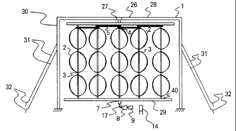
One of the features of the invention is a wind turbine structure shown in
FIG.14 comprising of
a 130-foot high fabricated steel rectangular frame of 80 feet in length and 40
feet wide. The frame
is attached to six footings at the ground level. The structure has 16 long
shafts of 3 inches in
diameter with 16 sets of blades on each shaft.
. The 256 sets of blades 1101 (900 RPM) gathering energy from the wind are
connected to the
rotor shafts 1102 supported by pillar box bearings 1103 attached to the
supporting structure
frame. There are 4 sets of 5-foot diameter blades in between each bearing and
structure support
beam. Each set of pillar box bearing housings would connect to a steel plate
attached to the steel
square tubing 1104 at every 20 foot length of the shaft. The 130-foot shaft is
connected on the
SUBSTITUTE SHEET (RULE 26)
CA 02356140 2001-06-19
WO 00/46510 PCT/US00/01133
-18-
ground level to a shaft speed increasing timing belt and pulley 1105 or
gearbox and eventually
to generator 1106. There could be a plurality of timing belts connecting the
generator in order to
optimize the number of generators to be activated for the determined wind
velocity or air flow.
The weight of each shaft and the blades on it is supported by a beefy tapered
roller bearing
1107 on the ground level. The generator and gearing areas of each shaft is
protected by a cage
1108 for safety reasons with a cage roof 1109to protect the generator and
gearing parts. The
gearing increases the rotation of the shaft (2 or 3 times) for the purpose of
converting the
mechanical energy into electrical energy by generator. A control unit
1110coordinates the
generator output with the utility grid. The (induction) generator has a RPM of
1800. I'he steel
structure is supported by 4 sets of guy wires 1111on each side.
Shown in FIG.15 is a typical 2 bladed Darrieus turbine set of blades at each
shaft section. The
blades 1101 are connected to shaft 1102. In FIG.16, each two blade set shown
in in FIG.15 is
perpendicular to the blade next to it on the shaft axis in order to reduce
mechanical stresses. A
pillar box bearing 1103 is at both ends of the shaft 1102 with blades 1101
connected to shaft
1102.
Shown in FIG.17 is a one bladed Darrieus turbine set of blades at each shaft
section. The
blade 1101 are connected to shaft 1102. In FIG.18, each one bladed blade set
shown in FIG.17
is at a different angle along the axis to the blade for reducing torque ripple
next to it on the shaft
axis in order to reduce mechanical stresses. A pillar box bearing 1103 is at
both ends of the
shaft 1102 with blades 1101 connected to shaft 1102. The one larger blade
allows for the same
solidity and efficiency while taking advantage of one larger blade for added
strength.
Illustrated in FIG. 19 is the current preferred embodiment of smaller and
thinner steel tubing
and an alternative version comprising of bigger and fewer steel supports.
Steel tubing connectors
could be an improved method used for easier and faster construction. The use
of pipe fittings
SUBSTITUTE SHEET (RULE 26)
---_-
_..._..__
~..,~.o .~... _ _
CA 02356140 2001-06-19
WO 00/46510 PCTIUSOO/01133
-19-
could accelerate construction and reduce cost. The frame or structure could be
built in an
assembly line approach in pieces and put together on the ground at the
location. Then, it could be
raised for connection.
In FIG.20, a single shaft showing a plurality of blades is illustrated and
placed inside a lattice
tower.
It is a feature of the invention to have a shaft mounting plate 1120 connected
to the frame
structure as shown in FIG.21. Two pillar box bearings 1103 are shown to be
placed near each
other or about one foot in the preferred embodiment in order to reinforce the
alignment of the
shaft. The Shaft mounting plate with two bearings are place on a horizontal
elongated structure
every 20 feet or a similar distance in the preferred embodiment.
An added feature of the invention is the blade joints shown in FIG. 22 A blade
1101 is
connected to a bracket 1130 which is welded to shaft 1102. In FIG. 23 a mass
production front
view is illustrated using a bolt -like clamp on an identical bolt-like clamp
on the other side of the
shaft. In FIG. 24 side view the clamp connected the the blade 1101 and shaft
1102 is given.
In FIG. 25, a top view of a cage roof with a weather protection washer
connected to the shaft
is shown. Shaft 1152 is connected to the washer showing outer diameter 1150 of
the washer and
edge 1152 of the hole in the cage roof below the weather washer.
The turbine may include air flow acceleration devices like augmentors or have
a larger
structure wherein the prevailing wind positions are not prevalent.
It will be understood that each of the elements described above, or two or
more
together, may also find a useful application in other types of construction
differing from
the type described above.
While the invention has been illustrated and described as embodied in a
virtual axes
turbine, it is not intended to be limited to the details shown, since it will
be understood
SUBSTITUTE SHEET (RULE 26)
CA 02356140 2001-06-19
WO 00/46510 PCT/USOO/01133
-20-
that various omissions, modifications, substitutions and changes in the forms
and details
illustrated and in its operation can be made by those skilled in the art
without departing in
any way from the spirit of the present invention.
The foregoing description of the preferred embodiment of the invention has
been
presented for the purposes of illustration and description. It is not intended
to be
exhaustive or to limit the invention to the precise form disclosed. Many
modifications
and variations are possible in the light of the above teaching. It is intended
that the scope
of the invention be limited not by this detailed description, but rather by
the claims
appended hereto.
Without further analysis, the foregoing will so fully reveal the gist of the
present
invention that others can, by applying current knowledge, readily adapt it for
various
applications without omitting features that, from the standpoint of prior art,
fairly
constitute essential characteristics of the generic or specific aspects of the
invention.
What is claimed as new and desired to be protected by Letters Patent is set
forth in
the appended claims.
While the invention has been described in connection with a preferred
embodiment, it is not intended to limit the scope of the invention to the
particular
form set forth, but on the contrary, it is intended to cover such altematives,
modifications, and equivalents as may be included within the spirit and scope
of
the invention as defined by the appended claims.
SUBSTITUTE SHEET (RULE 26)