Note: Descriptions are shown in the official language in which they were submitted.
CA 02356271 2001-06-22
WO 00/39576 PCT/US99/30494
A HYBRID 3-D PROBE TRACKED BY MULTIPLE SENSORS
FIELD OF THE INVENTION
This invention relates to an improvement in systems for measuring the position
and
orientation of probes and other rigid bodies being tracked in 3-dimensional (3-
D) space. The
improvements engendered by this invention can be applied to 1-dimensional and
2-dimensional
measurement systems, but the description herein describes the invention in the
more general
- - - -- context of measurements in three dimensions.
DESCRIPTION OF T$E BACKGROUND ART
Various methods and systems exist in the art to track the locations of points
(markers) in
a spatial volume defined by some 3-D coordinate system. By attaching multiple
markers to
bodies, even moving bodies, the orientation as~well as the position of the
bodies, individually or
in relationship to each other, can be determined. For example, such bodies may
be hand-held
probes, moveable rigid objects, or semi-rigid portions of human anatomy.
(Hereinafter, the position of a body means its 3-D location plus its 3-D
orientation about
that location. One common way of expressing this is as X, Y, and Z location
coordinates and as
yaw, pitch, and roll orientation angles. This is often referred to as six-
dimensional information,
or six degrees of freedom.)
A number of these methods and systerris have been described in previous
literature and
have been used in practice. The description belov~r will concentrate on light
based-electronic
tracking methods which use two or more light based sensors to measure the
angular locations of
markers on an object being tracked with respect to known positions of the
sensors in the three
CA 02356271 2001-06-22
WO 00/39576 PCT/US99/30494
2
dimensional volume. Examples of such prior art techniques are found in the
following
disclosures, which are herein incorporated by reference:
H. Fuchs, J. Duran, B. Johnson, and Zvi: M. Kedem; "Acquisition and Modeling
of
Human Body Form Data", Proc. SPIE, v. 166, 1978, p 94-102.
Jean-Claude Reymond, Jean-Luc Hidalgo; "System for monitoring the movements of
one
or more point sources of luminous radiation", U.S. Patent 4,209,254, 1980 June
24.
Y. Yamashita, N. Suzuki, M. Oshima; "Three-Dimensional Stereometric
Measurement
System Using Light based Scanners, Cylindrical Lenses, and Line Sensors",
Proc. SPIE,
v. 361, 1983, p. 67-73.
F. Mesqui, F. Kaeser, and P. Fischer; "Real-time, non-invasive recording and 3-
d display
of the functional movements of an arbitrary mandible point", SPIE
Biostereometrics 602,
1985, p 77-84.
Sharon S. Welch, Kevin J. Shelton, and James I. Clemmons; "Light based
position
measurement for a large gap magnetic suspension system", Proc. of the 37th
International Instrumentation Symposium, San Diego, 1991 May 5-9, p. 163-182.
Farhad Daghighian; "Light based position sensing with duolateral photoeffect
diodes",
Sensors, 1994 November, p. 31-39.
Robert P. Burton and Ivan E. Sutherland; "Twinkle Box-A three-dimensional
computer
input device", AFIPS Conference Proceedings 43, 1974, Chicago, Illinois.
The markers in the above systems emit : energy, and typically each marker is
an active
light source, such as an infrared or visible light emitting diode (LED). Other
systems have been
constructed to track highly reflective passive markers, and typically each
such passive marker is
a small patch or sphere coated with retm-reflective material, like that used
on highway signs. By
illuminating these markers with a light source near the sensors, a larger than
normal amount of
light is reflected back from the markers to the sensors, making the markers
appear brighter than
the background or other objects, thereby increasing their visibility and
simplifying the process of
finding them. Examples of commercial passive 3-D position measurement systems
are the
following:
The VectorVision system by BrainLAB GmbH (Heimstetten, Germany)
CA 02356271 2001-06-22
WO 00/39576 PCT/US99/30494
3
The Peak Motus system by Peak Performance Technologies, Inc. (Englewood,
Colorado)
The Eagle EyeTM system by Kinetic Sciences (Vancouver, British Columbia)
However, the limiting problem in all such systems, whether using active or
passive light based
markers, is maintaining line-of sight between the markers (reflectors or
emitters) and the
multiple sensors.
A number of non-light based 3-D measurement systems are known that do not
present the
line-of sight limitations. For example, coordinate measurement machines (CMMs)
and jointed
mechanical arms do not require the marker to be within line of sight of the
sensors, but they do
require the tactile accessibility of a probe through rigid mechanical
linkages, and this generally
presents as much of a restriction on the accuracy and ease of operation as
line-of sight
limitations. Further, these mechanical means are generally slower and more
awkward to use than
light based systems. For example, Carl Zeiss IMT Corp. (Minneapolis,
Minnesota), Romer Inc.
(Carlsbad, California), and FARO Inc. (Lake Mary, Florida) manufacture such
systems.
Other three-dimensional measurement systems that avoid the line-of sight
limitations
include magnetic field based systems manufactured and sold by Polhemus Inc.
(Colchester,
Vermont) and Ascension Technology Corp. (Burlington, Vermont). The major
drawback to such
systems is that their accuracy is considerably degraded by the proximity of
conductive objects,
especially ferrous metals, and most especially large masses of ferromagnetic
materials, such as
X-ray machines and other operating room apparatus. See also U.S. Patents
3,983,474,
4,017,858, 5,453,686, and 5,640,170. Improvements have been attempted
employing
combinations of light based and other mensuration systems. The following
reference describes
one such combination of a light based and a magnetic tracking system for an
image guided
surgery application:
CA 02356271 2001-06-22
WO 00/39576 PCTNS99/30494
4
Wolfgang Birkfellner, Franz Watzinger, Felix Wanschitz, Rolf Ewers, and Helmar
Bergmann; "Calibration of Tracking Systems in a Surgical Environment", IEEE
Transactions on Medical Imaging 17, (to be published 1998 Nov.).
This reference describes calibrating a magnetic system for local anomalies by
reference to
a light based system before use of the magnetic system. It does not disclose
continuous, dynamic
registration of multiple (e.g. two) tracking systems during application, as
will be discussed
below. Furthermore, it does not describe light based tracking of the magnetic
system's field
source generator.
One very desirable tracking system incorporates at least three built-in,
orthogonal,
miniature accelerometers and at least three built-in, orthogonal, miniature
gyroscopes (or their
equivalents) operatively associated with a probe or other tracked body. Such a
system is
desirable because it assumes that the accuracies of the accelerometers are
very precise and that
their operations are very stable over time. Unfortunately, to determine the
absolute position and
angular orientation of the probe or other objects in three dimensional space,
their linear and
angular acceleration must be integrated twice with respect to time.
Furthermore, the slow
rotation of Earth continuously affects all the angular measurements that are
unaligned with the
Earth's poles. In other words, any tiny constant calibration error in the
acceleration quickly
accumulates into an unacceptably large error. Therefore, the sensors must be
recalibrated very
frequently, perhaps every minute or two, in order for their accuracy to be
acceptable, particularly
for medical tracking applications. Therefore, by itself, an inertia-based
mensuration system is
not very practical for submillimeter measurements and the minute accelerations
experienced by a
hand-held probe. However, a sufficiently accurate, inertia-based probe would
be practical, if it
could be recalibrated frequently (or better yet continuously) using some
independent reference
system.
CA 02356271 2001-06-22
WO 00/39576 PCT/US99/30494
SUMMARY OF THE INVENTION
Therefore, this invention presents an improvement in position measurement that
combines the precision and robustness of light based tracking with another
tracking system that
does not have the "line of sight" limitations, such as: magnetic or inertial
tracking, or ultra-
5 sound, or any combination thereof. The result is a mensuration system that
improves the
accuracy or freedom of movement of the tracking system combination as compared
to any of the
individual tracking technologies alone.
The first objective of the present invention is to track the location of a
probe or other
object using a plurality of physical methodologies in such a way that results
achieved by the
combination are better than the results achieved using any one of individual
constituent
methodologies.
A second objective of this invention is to provide an automatic means to use a
constituent
methodology that has the best accuracy at any particular point in time and/or
in space to
continuously or frequently recalibrate the other constituent methodology (or
methodologies) that
1 S have less accuracy at that point.
A third objective of this invention is to provide the operator of the system
with a warning
when the estimated inaccuracy position and orientation of the probe, or other
tracked body or
object, exceeds a prescribed limit.
Other and additional objects will become apparent from a consideration of the
entirety of
this specification, the attached drawing and the appended claims.
To meet these and other objectives, one aspect of the invention comprises a
system for
tracking the position and orientation of one or more bodies comprising
multiple sensors that
sense position and orientation and/or movement of the bodies using more than
one form of
CA 02356271 2001-06-22
WO 00/39576 PCT/US99/30494
6
physical phenomena, an associated control unit, and means (preferably
automated) to perform
geometric computations.
The following paragraphs describe the present invention in terms of two
preferred
embodiments that employ specific means and a specific method for determining
the position and
orientation of moveable, substantially rigid bodies in 3-D space. Alternative
means and methods
are also mentioned in the text, but other unmentioned, comparable means and
methods exist or
will be developed that can implement the methods of the invention. All of such
comparable
means are intended to be embraced by this invention.
BRIEF DESCRIPTION OF THE DRAWINGS
The accompanying figures illustrate two preferred embodiments of the present
invention
and form a part of the specification. Together with the textual description,
these figures serve to
explain the advantages and principles of the instant system. Each reference
number in the figures
consistently refers to the same component of the instant system throughout all
the figures and
throughout the textual description.
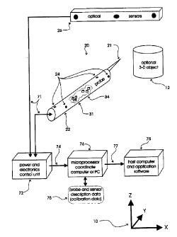
Figure 1 is a combination of a schematic block diagram and a perspective view
of a single
object being tracked, that represents a preferred embodiment of the present
system, using a
combination of light based and inertial subsystems to track the object. The
probe is shown
enlarged to enable internal detail to be seen.
Figure 2 is similar to figure 1 except that a magnetic localizer subsystem has
been
substituted for the inertial subsystem of Figure 1. The probe is shown
enlarged to enable internal
detail to be seen.
CA 02356271 2001-06-22
WO 00139576 ,~ PCT/US99/30494
Figure 3 is a flow chart that outlines one preferred set of major steps of
operation and
computation performed by a coordinate computer for either of the preferred
embodiments or for
a combination thereof.
The components in the various figures are numbered as follows:
10 a fixed coordinate system describing a 3-D spatial volume
12 an optional object being tracked with surface points, dimensions, prominent
points, or other geometrical features that could be measured in that volume
20 at least one whole probe or other body being tracked three-dimensionally
21 an optional tip for probe 20 for measuring points on optional object 12
22 a body of a probe (with part broken-away to view part of its inside)
24 multiple light based detectable markers (such as infrared LED emitters or
reflectors of impinged electromagnetic radiation)
26 an array adapted to sense Iight beams for tracking the locations of the
markers
31 mutually perpendicular (micromachined) linear accelerometers
34 mutually perpendicular (micromachined) angular accelerometers
41 mutually perpendicular magnetic sensors
44 mutually perpendicular magnetic field sources (coils) shown together in one
unit
47 optional markers sufficient to emit or reflect light beams attached to
magnetic
field sources
71 various data/signal paths between a control unit 72 and/or sensors or
emitters/reflectors
72 control unit for power, electronics, signal conditioning, timing, and other
support
CA 02356271 2001-06-22
WO 00/39576 PCT/US99/30494
8
systems
74 a stream of individual sensor measurements
75 probe and/or sensor description data (including calibration parameters)
76 a computational computer (personal computer or embedded microprocessor)
S 77 a stream of 3-D position and 3-D orientation coordinates (and optional
time data)
78 host computer hardware and software that utilize the positional and
orientation
coordinates
80 the program that controls the system and computes position coordinates
81...99 individual steps of program 80 that manage the system
DETAILED DESCRIPTION OF TWO SPECIFIC EMBODIMENTS
The invention will be described below with reference to the figures and the
numbered
individual components therein. In the description below, the specific
construction, the number ,
and the arrangement of the components are intended for clarity of illustration
and are not
limitations on the scope of this invention. Other arrangements or quantities
of the components
constitute alternative specific embodiments of the same method, apparatus and
system.
Figures 1 and 2 illustrate two alternative preferred embodiments of the
present invention.
Figure 3 depicts as a flowchart the major steps 81...99 of the program that
operates the
coordinate computer 78 and other peripheral equipment. These program steps
apply to either or
both of the two embodiments and even to an embodiment that combines the
components of those
two.
With reference to figure 1, the apparatus includes a 3-D light based
measurement system,
such as the FlashPoint 5000 built by Image Guided Technologies, Inc., of
Boulder, Colorado.
CA 02356271 2001-06-22
WO 00/39576 9 PCT/US99/30494
The electromagnetic radiation sensors 26 detect the image of each light
emitting or reflecting
marker 24 on the probe or other body 20, where each marker is a light emitting
diode (LED) or a
passive reflector. The locations of the images of the markers are sent to a
control unit 72 via a
transmission means (such as a wire or wireless radio) 71. The control unit 72
processes each
image into sensor coordinates and transmits the same, via line 74, to a
coordinate computer 76
that computes the 3-D XYZ coordinates of each marker 24 using the sensor
coordinates from all
the sensors 26 and using calibration parameters 75. The actual means of
determining the location
of a marker (emitter or reflector) is described in United States patent
5,622,170, the entirety of
which is incorporated herein by reference. Note that more markers 24 than
shown in figure 1
may be used and not all markers need to be seen at the same time by the light
based sensors 26.
At least three non-collinear markers must be detected by the sensors 26 in
order to fully
determine the 3-D position and 3-D orientation of the probe. If the sensors
are one dimensional,
three sensors must detect the emissions or reflections. If the sensors are two
dimensional, at least
two sensors must detect the emissions or reflections. If the sensors are three
dimensional, only
one sensor needs to be intersected by emissions or reflections of
electromagnetic energy. In the
case of a probe of known geometry, a further simple computation could be used
to determine the
location of the probe tip 21 that is in a fixed position relative to the
markers.
If there is no explicit probe tip 21 that needs to be determined, then the
position and
orientation of the body 20 being tracked would be with respect to some
reference location on the
body, such as one of the markers 24. The details enabling the performance of
these individual
steps are disclosed in the references cited above.
In the preferred embodiment of Figure 1 the body also houses multiple linear
accelerometers 31, such as the ADXL202 manufactured by Analog Devices, Inc. At
least one
CA 02356271 2001-06-22
WO 00/39576 PCT/US99/30494
accelerometer 31 should be aligned with each of the body's three dimensional
axes.
Furthermore, the embodiment may also include a plurality of angular
accelerometers 34 (also
known as solid state or piezoelectric gyroscopes). For example, three
accelerometers can be
used. Examples of such devices are the G-2000 manufactured by Litton Guidance
& Control
5 Systems (Salt Lake City, Utah) or the Gyrostar by MuRata Erie (Smyrna,
George). These
manufacturers publish drift specifications that disclose how long the angular
accelerometers 34
will perform within the required orientation accuracy before needing
recalibration.
One way to calibrate the non-light based sensors with respect to the light
based system is
to calculate the rigid linear transformation that relates the 3-D position as
determined by the non-
10 light based sensors to the 3-D position, as determined by the light based
system. A rigid linear
transformation is commonly described as a rotation R about some axis through
the origin
followed by a translation (shift) S in 3-D space. The rotation may be
described as a sequence of
yaw, pitch, and roll angles or as Euler angles. However, it is generally more
convenient to use
either a quaternion or an orthonormal 3-by-3 matrix R to represent the
rotation. The translation S
is represented by a 3-D vector. So, for example, a coordinate triple [X' Y'
Z'] computed by the
non-light based subsystem is related to a coordinate triple [X Y Z] computed
by the light based
subsystem as follows:
[ X Y Z ] - [ X' Y' Z' ] * R + S
where * is matrix multiplication and + is vector addition.
For details, see any college text on linear algebra, or see Computer Graphics:
Principles and
Practice by Foley, van Dam, Feiner, and Hughes (Addison Wesley, New York,
1990).
As the non-light based sensors 31, 34 drift or exhibit bias, the numbers in
the linear
transformation will slowly vary. Sometimes the variance is at a substantially
constant rate. By
CA 02356271 2001-06-22
WO 00/39576 PCT/US99/30494
11
keeping track of the rate of change (rotation and translation) with respect to
time and/or
temperature and/or other environmental factors, the system can internally
estimate the inaccuracy
of the non-light based sensor.
While sufficient light based markers are in line-of sight of the light based
sensors, the
linear transformation is frequently recomputed. When insufficient markers
become visible to the
sensors, the last-computed transformation is used to correct the positional
computations from the
other, non-light based, e.g. inertial, subsystem. In a more preferred system,
the linear
transformation is continually altered at the same rate at which it had been
most recently
changing. This usually will allow the non-light based system to operate more
accurately for a
longer time because the inaccuracy that is most recently known from accurate
light based
tracking is being extrapolated using the most recent rate of change of
inaccuracy.
When the extrapolated inaccuracy exceeds some user-def ned limit (program Step
91 ) and
a sufficient number of light based markers on the tracked body are out of line-
of sight, then the
user is preferably notified of this condition, suitably by an audible or
visible indicator (program
Step 99). Coordinate data could still be produced by the micro processor 76
and recorded, but is
immediately suspect, and a warning indicator (such as a bad status code) is
preferably associated
with the questionable data that are being generated.
As shown in figure 2, a second preferred embodiment of this invention also
includes 3-D
light based sensors 26 and whatever circuitry in the control unit 72 is
required for support.
However, the linear and angular accelerometers 31, 34 unlike the system of
figure 1, are replaced
with magnetic sensors 41 that are preferably, but not necessarily, located in
the body 20. Also, a
steerable magnetic field source 44 is provided. The location of the several
sensors 41 can thus be
determined, and from these locations the position and orientation of the body
20 (or bodies) with
CA 02356271 2001-06-22
WO 00/39576 PCT/US99/30494
12
which they are associated can be deduced. Such a sub-system is exemplified by
the products
referred to above as being manufactured and sold by Polhemus or Ascension.
In the simplest and most preferred implementation of this embodiment of this
invention,
the magnet field source 44 remains physically stationary and light based
markers 47 are not used.
(The magnetic field source 44, however, is steered electronically.) As the
probe or other body 20
is moved farther away from the magnetic field sowce 44, the mensuration
accuracy decreases at
a geometric rate that is proportional to the distance. Beyond a predetermined
distance, the
inaccuracy introduced by the distance of the body from the magnetic source
exceeds its accuracy
limit. If a sufficient number of light based markeis on the body 20 are
visible to the light based
sensors, the 3-D coordinates can be produced anyway using the light based
sensor information
alone. So the optimal location of the magnetic source 44 is proximate to
locations where the
body will be light based obscured, but where the magnetic based subsystem is
most accurate.
The body may then be tracked into the obscured volume, such as inside a
medical patient during
a catheter procedure.
A more preferred implementation of the embodiment of Figure 2 employs
additional light
based markers 47 on the magnetic field source 44. Assuming that a least 3 non-
collinear markers
47 are visible to the light based sensors 26, the position and orientation of
the magnetic field
source 44 can be determined in just the same way as any other body, such as
object 20. Unlike
the simpler implementation described in the previous paragraph, the magnetic
field source 44 can
then be moved dynamically while its position and orientation are still being
tracked. It will
always be moveable to a position and orientation at which it is visible to the
light based sensors
26 and yet be close enough to the magnetic sensors 41 to allow the generation
of sufficient
magnetic based data to relatively accurately determine coordinates even when
the markers 24 on
CA 02356271 2001-06-22
WO 00/39576 PCT/US99/30494
13
the body 20 are not in a line of sight with the light based sensors. In this
case, the linear
transformation relating the magnetically derived XYZ coordinates to the light
derived XYZ
coordinates must include the linear transformation between the moveable
magnetic field source
44 and the fixed light based sensors 26. This is not unlike the transformation
required in U.S.
Patent 5,198,877 (incorporated by reference), in which the locations of points
are determined
relative to a freely moveable 3-D measurement system, which is itself tracked
by another 3-D
measurement system.
Note that it is theoretically possible in the above described system to
interchange the
cluster of magnetic sensors 41 with the magnetic source 44, because the 3-D
measurement
simply tracks one magnetic component relative to the other. However, the
magnetic source is
generally larger and bulkier and not well suited to be incorporated in a hand-
held probe.
Furthermore, the system would then be limited to tracking only one body 20,
the body holding
the magnetic source. For similar reasons, it is theoretically possible, but
perhaps impractical, to
interchange the roles of the light based sensors and the light based
markers/reflectars.
Note that the systems of figure 1 and figure 2 are nat mutually exclusive. It
is possible to
provide a probe containing both accelerometers and magnetic sensors (or even
yet other position
measurement systems, such as ultra sound transducers). When a sufficient
number of light based
markers on a probe are within view of the light based sensors, both of the non-
light based
subsystems are continuously recalibrated. When insufficient markers are
visible, then one or
both non-light based sensor sub-systems are used to determine the position and
orientation of the
body (probe). Each sub-system provides an internal estimate of its own
inaccuracy. If only one
estimate exceeds the limit, then the data from the other sub-system is used.
If neither exceeds the
limit, then either sub-system can be used or the (weighted) average of the
coordinates produced
CA 02356271 2001-06-22
WO 00/39576 14 PCT/US99/30494
by the two subsystems can be used. If neither sub-system is within acceptable
inaccuracy limits,
the results reported by the system are suspect and should be flagged.
With reference to figure 3, the operation of the present invention begins in
Step 81 by
initializing the light based and inertial/magnetic sub-systems and by
initializing the inaccuracy
estimate for these non-light-based sub-systems to an unacceptably large value
in order to force
the system to calibrate the non-light based sub-systems) to the reference
light based subsystem,
after which the inaccuracy is reset to zero in Step 87. (That is, the large
initial inaccuracy
estimate will alert the user in Step 99 to place the body in a position where
the light based sub-
system is operational, if that is not already the case.) Steps 82 and 83
determine whether the
light based sensors can see enough of a body's markers 24 to make a reliable 3-
D position
measurement of the body 20. If so, Step 84 performs the measurement as well as
computing the
location and direction of the tip 21 if it exists and if it is desired. Step
85 does the same using the
non-light based sub-system(s). Step 86 relates these two measurements to each
other by using an
orthonormal linear transformation as described above or using some other
method. Step 87
resets the inaccuracy limit to zero (or some other small appropriate
estimate). Lastly, Step 95
reports the coordinates derived from information provided by the light based
sensors 26 through
the microprocessor 76 and to the host computer 78 before the cycle repeats at
Step 82. Note that
the coordinate reports could be accompanied by reports of the non-light based
coordinates too,
the inaccuracy estimate, a time stamp, and a "success" status code.
If the light based system cannot see enough markers 24 on a body 20, then
Steps 90 and
91 are adapted to check the current other nan-light based sub-system
inaccuracy estimate. If it
exceeds a preset limit, then the user is preferably visually or audibly warned
about this condition
in Step 99. Although not shown, the coordinates could still be reported by
Step 95, but some
CA 02356271 2001-06-22
WO 00/39576 15 PCTNS99/30494
"warning" status code should be attached to the data. If the inaccuracy
estimate of the other non-
light based sub-system is within the limit, Step 92 reads that non-light based
sensors 31, 34,
and/or 41, and Step 93 computes the position and orientation of the body 20
and the location and
direction of its tip 21, if appropriate. Step 94 updates the current other non-
light based sub-
system estimated inaccuracy based on elapsed time since Step 87 was executed
or based on
distance of the body 20 from the magnetic source 44 or based on other
environmental factors like
temperature. Step 95 reports the position coordinates derived from the non-
light based sensors
31-34 and/or 41 and continues to repeat the cycle again at Step 82.
The principles of this invention may be applied to measurement technologies
beyond the
Z O magnetic and inertial technologies discussed in detail in the foregoing
preferred embodiments.
For example, a previous U.S. patent application (60/096,907) has described a
non-line-of sight
flexible shaft method of determining 3-D points or tracking a body. If, for
illustration, that
method suffers from bad accuracy in certain parts of its measurement volume or
if the accuracy
degrades as the shaft is flexed over time or during temperature changes,
auxiliary light based or
other subsystem could be employed to recalibrate the flexible shaft frequently
whenever the
probe end of the shaft (equipped with visible markers) is in view of the light
based sensors.
The above description is based on the use of light based sensors as the
primary
(reference) position measurement subsystem. However, any type of position
sensor can be used
as the primary position measurement system. Any primary system can be combined
with any
one or more secondary measurement system such as a combination of inertial and
magnetic
subsystems. In an appropriate case, the magnetic subsystem could be used to
correct the inertial
subsystem from time to time, or vice versa. The advantage of this combination
is that the inertial
CA 02356271 2001-06-22
WO 00/39576 PCT/US99/30494
16
system can be used for short periods of time at a distance that is beyond the
higher-accuracy
available by the magnetic sensors being close to the magnetic source.