Note: Descriptions are shown in the official language in which they were submitted.
CA 02356395 2001-06-22
WO 00/41264 PCTIUS99I30901
_]_
REDUCED LEAKAGE METAL-AIR ELECTROCHEMICAL CELL
The invention generally relates to metal-air electrochemical cells.
Batteries are commonly used electrical energy sources. A battery
contains a negative electrode, typically called the anode, and a positive
electrode,
typically called the cathode. The anode contains an active material that can
be
oxidized; the cathode contains or consumes an active material that can be
reduced.
The anode active material is capable of reducing the cathode active material.
In
order to prevent direct reaction of the anode material and the cathode
material, the
anode and the cathode are electrically isolated from each other by a sheet-
like layer,
typically called the separator.
When a battery is used as an electrical energy source in a device, such
as in a hearing aid, electrical contact is made to the; anode and the cathode,
allowing ,
electrons flow through the device and permitting tlxe respective oxidation and
reduction reactions to occur to provide electrical power. An electrolyte in
contact
with the anode and the cathode contains ions that flow through the separator
between
the electrodes to maintain charge balance throughout the battery during
discharge.
One configuration of a battery is a button cell, which has the
approximate size and cylindrical shape of a button,. in a button cell, the
container for
the anode and the cathode includes a Lower cup-like structure, called the
cathode can,
and an upper cup-like structure retained within the cathade can, called the
anode can.
The anode can and cathode can be separated by ar.~ insulator, such as an
insulating
gasket or seal. The anode can and the cathode can are crimped together to form
the
container.
In a metal-air electrochemical cell, oxygen is reduced at the cathode,
and a metal is oxidized at the anode. Oxygen is supplied to the cathode fiom
the
atmospheric air external to the cell through an air access port in the
container. When
the electrolyte in the cell is aqueous, hydrogen gas can be produced in the;
anode of
the cell. Gas generation can lead to pressure build up in the cell, ultimately
resulting
in leakage or structural failure of the cell. The metal of a metal-air
electrochemical
cell can be zinc. Typically, when zinc is used in a metal-air battery, the
zinc is
alloyed with mercury (e.g., about 3 percent) to reduce hydrogen gas evolution.
In general, the invention relates to a metal-air electrochemical cell
CA 02356395 2001-06-22
WO 00/41264
-2-
PCTIUS99/30901
which exhibits good discharge performance under re:latively high temperature,
high
humidity conditions. Leakage from the cell can be reduced. Relatively high
temperature, high humidity conditions are temperatc~re between about
25°C and about
38°C (e.g., 30°C) and a relative humidity external of the cell
of between about 45
and about 95 percent (e.g., between 70 and 90 percent).
The high temperature, high humidity conditions are similar to the
ambient conditions the cell is exposed to during use (e.g., about 30°C
and 90 percent
relative humidity). For example, a zinc-air cell can be used in a high
temperature
and high humidity geographic location, such as the Far East, or in an hearing
aid
which is not hermetically sealed. The hearing aid is placed in an ear canal.,
which
has a high relative humidity and a high temperature: It is important that the
cell have
good discharge performance and resists leakage under these operating
conditions.
In one aspect, the invention features a metal-air electrochemical cell
including an anode, a cathode, and a separator electronically separating the
anode and
the cathode. The anode includes an anode can containing an anode gel. The
anode
gel includes an electrolyte. The cathode includes a cathode can having at
least one
air access port and containing a cathode structure. An insulator can be
Iocated
between the anode can and the cathode can. The cathode structure can include a
catalyst mixture and a current collector in electrical contact with the
cathode can.
The cell can further include an air disperser positioned between the air
access port
and the cathode structure. The anode can and cathode can are assembled (e.g.,
crimped together) to form a cell.
In the anode, the anode volume is the volume within the cell contained
between the inner surface of the anode can and the separator. The anode gel
occupies most of the anode volume. The portion of the anode volume that is not
filled with the anode gel is the void volume. The: void volume of the cell
after
discharge is between about 7.5 percent and about 15 percent of the anode
volume.
Preferably, the void volume is between about 8 percent and about 12 percent
(e.g.,
about 10 percent) of anode volume.
Overall cell height and diameter dimensions are specified by the
International Electrotechnical Commission (IEC). A cell can have one of five
sizes:
a 675 cell (IEC designation "PR44") has a diameter between about I 1.25 and
11.60
CA 02356395 2001-06-22
WO 00141264
PCT/US99/30901
-3-
millimeters and a height between about 5.0 and 5.4 millimeters; a 13 cell (IEC
designation "PR48") has a diameter between about '7.55 and 7.9 millimeters and
a
height between about 5.0 and 5.4 millimeters; a 312 cell (IEC designation
"PR41 ")
has a diameter between about 7.55 and 7.9 millimeters and a height of between
about
3.3 and 3.6 millimeters; and a 10 cell (IEC designation "PR70") has a diameter
between about 5.55 and 5.80 millimeters and a height between about 3.30 and
3.60
millimeters. A 5 cell has a diameter between about 5.55 and 5.80 millimeters
and a
height between about 2.03 and 2.16 millimeters. The cell can have an anode can
thickness of about 0.1016 mm. The cell can have an cathode can thickness of
about
0.1016 mm.
The metal-air electrochemical cell can be a 675 cell. The 675 cell can
have a discharge performance of between about 700 mAh and about 480 rnAh at a
temperature between about 25°C and about 38°C (e.g.,
30°C) and a relative humidity
external of the cell of between about 45 and about 95 percent. Preferably, the
discharge performance of the 675 cell is between about 680 mAh and about 510
mAh, more preferably between about 660 mAh and about 550 mAh (e.g., about 600
mAh).
The metal-air electrochemical cell c;an be a 13 cell. The 13 cell can
have a discharge performance of between about 295 mAh and about 200 mAh cell
at
a temperature between about 25°C and about 38°C (e.g.,
30°C) and a relative
humidity external of the cell of between about 45 and about 95 percent.
Preferably,
the discharge performance of the cell is between about 290 mAh and about 220
mAh;
more preferably between about 280 mAh and about 230 mAh (e.g., about 260 mAh).
The metal-air electrochemical cell can be a 312 cell. The 312 cell can
have a discharge performance of between about 155 mAh and about 110 mAh for a
312 cell at a temperature between about 25°C and about 38°C
(e.g., 30°C) and a
relative humidity external of the cell of between about 45 and about 95
percent.
Preferably, the discharge performance of the 312 cell is between about 152 mAh
and
about 115 mAh, more preferably between about '150 mAh and about 120 mAh (e.g.,
about 135 mAh).
The metal-air electrochemical cell can be a 10 cell. The 10 cell can
have a discharge performance of between about 85 mAh and about 50 mAh at a
CA 02356395 2001-06-22
WO 00/41264
PCTIUS99/30901
_4-
temperature between about 25°C and about 38°C (e.g.,
30°C) and a relative humidity
external of the cell of between about 45 and about 95 percent. Preferably, the
discharge performance of the 10 cell is between about 84 mAh and about 55 mAh,
more preferably between about 82 mAh and about 60 mAh (e.g., about 70 mAh).
The metal-air electrochemical cell can be a 5 cell. The 5 cell can have
a discharge performance of between about 45 mAh and about 40 mAh (e.g., about
43
mAh) at a temperature between about 25°C and about 38°C (e.g.,
30°C) and a
relative humidity external of the cell of between about 45 and about 95
percent.
In another aspect, the invention features a method of manufacturing a
metal-air electrochemical cell. The method includes assembling an anode and a
cathode to form a cell having a void volume after discharge of between 7.5
percent
and about I S percent of the anode volume.
In another aspect, the invention features a method of reducing leakage
of electrolyte from a metal-air electrochemical cell. The method includes
assembling
an anode and a cathode to form a cell. The anode is assembled to have a void
volume after discharge being between about 7.5 percent and about 15 percent of
the
anode volume.
The metal-air electrochemical cells o.f the invention can have improved
discharge performance under conditions of high temperature and high humidity
relative to 20°C and 50 percent relative humidity. The cells have a
reduced tendency
of leaking relative to low void volume cells. Under high temperature and thigh
humidity conditions, moisture can enter the cell, building up hydrostatic
pressure in
the cell. The hydrostatic pressure can lead to flooding of the cathode with
electrolyte
and, ultimately, disabling of the cell. The higher void volume of the cell
increases
the tolerance of the cell to take up atmospheric moisture. As void volume is
increased, the capacity of the cell decreases. The void volume can be selected
to
reduce leakage and improve discharge performance: while maintaining adequate
cell
capacity.
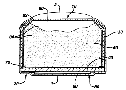
FIG. 1 depicts a cross-sectional view of a metal-air cell.
The metal-air electrochemical cells can be zinc-air cells having a
relatively high void volume. The zinc-air batteries exhibit good discharge
performance under relatively high temperature, high humidity conditions, such
as at
CA 02356395 2001-06-22
WO 00/41264
-5-
PCT/US99130901
30°C and 90% relative humidity. By including a void volume of greater
than 7.5
percent and Less than 1 S percent in the cell, significant gains in cell
performance can
be achieved at relevant temperatures and humidities. In addition, the
likelihood of
leakage can be reduced.
A zinc-air cell can be a button cell. Referring to FIG. 1, a button cell
includes anode 2 and cathode 4. Anode 2 includes anode can 10 and anode gel
60.
Cathode 4 includes cathode can 20 and cathode structure 40. Insulator 30 i s
located
between anode can 10 and cathode can 20. Separator 70 is located between
cathode
structure 40 and anode gel 60, preventing electrical contact between these two
components. Air access port 80, located in cathode can 20, allows air to
exchange
into and out of the cell. Air disperser 50 is located between air access port
80 and
cathode structure 40.
Anode can 10 and cathode can 20 are crimped together to form the cell
container, which has an internal volume, or cell volume. Together, inner
surface 82
of anode can 10 and separator 70 form anode volume 84. Anode volume 84
contains
anode gel 60. The remainder of anode volume 84 is void volume 90.
A zinc-air cell uses zinc as the electrochemically active anode material.
The anode gel contains a mixture of zinc and electrolyte. The mixture of zinc
and
electrolyte can include a gelling agent that can hell> prevent leakage of the
electrolyte
from the cell and helps suspend the particles of zinc within the anode. The
cathode
structure contains a material (e.g., a manganese compound) that can catalyze
the
reduction of oxygen which enters the cell as a component, of atmospheric air
passing
through access ports in the bottom of the cathode c;an. The overall
electrochemical
reaction within the cell results in zinc metal being oxidized to zinc ions and
oxygen
from air being reduced to hydroxyl ions. Ultimately, zinc oxide, or zincate,
is
formed in the anode. While these chemical reactions are taking place,
electrons are
transferred from the anode to the cathode, providing power to the device.
Void volume is determined after discharge of the cell. The anode
volume of the cell is established by the geometry of the cell and the
dimensions of
the components. The amount of the anode volume occupied by the anode gel is
determined by the volume of anode gel added to the cell. As a zinc-air cell is
discharged, the zinc of the anode gel is oxidized to zinc oxide. The oxidation
of the
CA 02356395 2001-06-22
WO 00/41264
-6-
PCTIUS99l30901
zinc increases the volume occupied by the anode gel, since the density of zinc
is
higher than the density of zinc oxide. The volume of the anode gel expands
during
discharge due to the larger volume occupied by the oxidized zinc. The amount
of
expansion of the anode gel after discharge can be calculated from the zinc
content of
the gel and the change in density of the zinc component. The anode gel volume
after
discharge can then be calculated by adding the volmne of expansion to the
anode gel
volume before discharge. Accordingly, the void volume after discharge can be
calculated by taking the difference between the anode volume and the anode gel
volume after discharge. Void volume 90 after discharge can be between about
7.5
percent and 15 percent. The increased void volume can assist in reducing
leakage of
electrolyte from the cell.
The cathode structure has a side facing the anode gel and a side facing
the air access ports. The side of the cathode structure facing the anode gel
is covered
by a separator. The separator can be a porous, electrically insulating
polymer, such
as polypropylene, that allows the electrolyte to contact the a.ir cathode. The
side of
the cathode structure facing the air access ports is typically covered by a
polytetrafluoroethylene (PTFE) membrane that can help prevent drying of the
anode
gel and Leakage of electrolyte from the cell. Cells can also include an air
dispenser,
or blotter material, between the PTFE membrane and the air access ports.
The air dispenser is a porous or fibrous material that helps maintain an
air diffusion space between the PTFE membrane and the cathode can. The air
dispenser can be hydrophilic and absorbent, allowing it to soak up any
moisture in the
cathode side of the cell. The dispenser can also limit damage done by
electrolyte
solution if it penetrates the cathode, which can oc<:ur under higher
temperature and
humidity conditions, particularly when the void valume of the cell is not
large
enough to compensate for gas generation in the anode.
The cathode structure includes a current collector, such as a wire mesh,
upon which is deposited a cathode mixture. The wire mesh makes electrical
contact
with the cathode can. The cathode mixture includes a catalyst for reducing
oxygen,
such as a manganese compound. The catalyst mixture is composed of a mixture of
a
binder (e.g., PTFE particles), carbon particles, and manganese compounds. The
catalyst mixture can be prepared, for example, by heating manganese nitrate or
by
CA 02356395 2001-06-22
WO 00/41264 PCT/US99/30901
_7_
reducing potassium permanganate to produce manganese oxides, such as Mn2O3,
Mn3O4 and Mn02.
The catalyst mixture can include between about 15 and 45 percent
polytetrafluoroethylene by weight. Fox example, the cathode structure can
include
about 40 percent PTFE, which can make the structure more moisture resistant,
reducing the likelihood of electrolyte leakage from 'the cell due to moisture
uptake
from the atmosphere.
The electrochemical cell includes an anode formed of an anode gel.
The anode gel includes an electrolyte, a zinc material, and a gelling agent.
In certain
embodiments, the mercury content of the zinc of the anode can be less than 3
weight
percent of the zinc. In other embodiments, the mercury content of the zinc of
the
anode can contain less than 2 weight percent mercury. The zinc material can be
a
zinc alloy powder that includes less than 2 percent mercury. The zinc alloy
can
include, for example, lead, indium, or aluminum. Suitable zinc materials
include zinc
available from Union Miniere (Overpelt, Belgium), Duracell (USA), Noranda
(USA),
Grillo (Germany), or Toho Zinc (Japan), or zinc materials described in U.S.
Ser. No.
08J905,254, filed August 1, 1997, and U.S. Ser. No. 09/i 15,867, filed July
15, 1998,
each of which is incorporated herein by reference.
Zinc-air anode materials are loaded into a cell in the following manner.
A gelling agent (about 0.33 weight percent) and zinc powder are mixed to form
a dry
anode blend. The blend is then poured into the anode can and electrolyte is
dispensed onto the dry anode blend to form the anode gel.
The gelling agent can be a polyacrylate, such as a sodium polyacrylate.
The gelling agent can be an absorbent polyacrylate. The anode gel includes
less than
1 percent by weight of the gelling agent in the anode mixture weight.
Preferably, the
gelling agent content of the anode mixture is between about 0.2 and 0.8
percent by
weight, more preferably between about 0.3 and 0.6 percent by weight, and most
preferably about 0.33 percent by weight. The anode geI can include a
surfactant or
other additives.
The electrolyte can be an aqueous solution of potassium hydroxide.
The electrolyte can include between about 30 and 40 percent of potassium
hydroxide.
The electrolyte concentration can affect the rate at which a cell takes up
water. The
CA 02356395 2001-06-22
WO OOI41264
-g-
PCTlUS99130901
higher the electrolyte concentration, the more water it tends to absorb from
the
atmosphere. The electrolyte can also include between about I and 2 percent of
zinc
oxide.
The anode can be composed of stainless steel having a copper layer on
the inner surface of the can and a nickel layer on the outer surface of the
can. The
cathode can be composed of cold-rolled steel having inner and outer layers of
nickel.
The insulator, such as an insulating gasket, pressure-fit between the anode
can and
cathode can. The insulator can be an insulating polymeric material, such as
nylon,
polypropylene, or polyethylene.
I p The can configuration can be a straight wall design, in which the
anode can is straight, or a foldover design, in which the clip-off edge of the
anode
can, generated during stamping of the can, is placed on the top, outside of
can, away
from the interior of the cell. A straight wall design can be used in
conjunction with
an L- or J-shaped insulator, preferably L-shaped, that can bury the clip-off
edge into
the insulator foot.
During storage, the air access ports sue typically covered by a
removable sheet, commonly known as the seal tab, that is provided on the
bottom of
the cathode can to cover the air access ports to restrict the flow of air
between the
interior and exterior of the button cell. The user peels the seal tab from the
cathode
can prior to use to allow oxygen from air to enter the interior of the button
cell from
the external environment.
EXAMPLES
The discharge capacities of five sizes of cells were calculated for three
different void volumes in Examples 1-5. Each of the cells had an anode can
thickness of about 0.152 mm and a cathode can thickness of about 0.203 mm. The
discharge capacities are listed in Table 1. The cell sizes correspond to the
IEC
designated cell sizes. The discharge capacities are based on discharge of zinc-
air
cells at 20°C and 50 percent relative humidity. The discharge
capacities of the 5%
void volume cells and 20% void volume cells are based on discharge
measurements
of fabricated cells. The reported discharge capacities at 10% void volume are
nominal capacities based on the anode weight required to achieve a 10% void
volume, minus an estimate of anode efficiency losses. The anode efficiency
losses
CA 02356395 2001-06-22
PCT/US99130901
WO 00/41264
-9-
were estimated from those observed for
5% void volume and 20% void volume cells.
TA~ BLE I
Void Volume 5% 10% 20%
Example Cell Size Capacity Capacity Capacity
(~) (~h) (mAh)
1 675 610 560 480
2 13 260 240 200
3 312 i35 125 110
4 10 70 65 50
5 5 45 43 40
The discharge capacities of five sizes of cells having thinner
can wall
thicknesses than in Examples 1-5 were
calculated for. three different void
volumes in
Examples 6-10. Each of the cells had anodeckness of about 0.1016
can thi mm and a
cathode can thickness of about 0.1016
mm. The oui:er dimensions of the cells
fell
within the IEC designated ranges for The discharge capacities
each cell size. are
listed in Table II.
TABLE II
Void Volume 5% 10% 20%
Example Cell Size Capacity Capacity Capacity
) (~) (mA.h)
6 675 700 645 585
7 13 295 275 225
g 312 155 145 130
g 10 85 80 62
10 5 45 43 40