Note: Descriptions are shown in the official language in which they were submitted.
06/20/01 WED 11:15 FAX 1212 972 5487 CA 02356609 2001 -o6 21
jI ET AL I~] 003
5095-43PUS
PCT/DE99/03,959
WO 00/37,200
PROCESS FOR PRODUCING ROUND BILLETS
S P E C I F I C A T I O N
The invention pertains to a process for the production of
continuous -cast billets in a production plant consisting of a
vertical, round strand-casting machine with horizontal run-out,
at least one descaling device, and several following roll stands.
After they have solidified, the billets produced in a
vertical, round strand-casting machine with horizontal run-out
may show differences in the material concentrations over their
cross section. For example, porous areas occur in almost all
steels just underneath the surface and in the core. Especially
affected by this phenomenon are the free-cutting steels. Carbon-
manganese steels have segregations in the core area, which impede
the production of high-strength wire, for example. In the case
of high-carbon chromium steels, "hairs" form in the core, which
impair the quality of the inside surface of high-precision rolled
tubular products. Depending on their chemical composition,
austenitic stainless chromium-nickel steels can contain a large
amount of 6-ferrite in some cases as a second phase, which, in
the case of round billets, has a pronounced maximum at a distance
from the core equal to 0.4-0.7 x the radius; this phase
significantly impairs the deformability of these steels during
the following cross-rolling process, because the main deformation
zone is in this cross-sectional area. As a result, only limited
degrees of elongation can be realized. General problems with
deformability in the form of tears and peeling start to occur as
soon as the average S-ferrite content exceeds 4%.
1
06/20/01 WED 11:15 FAX 1212 972 5487 CA 02356609 2001-06y21 I ET AL
Q 004
There are various causes of these material inhomogeneities.
By way of example, the following can be cited here; material
data, material impurities, molten metal temperature, casting
flux, mold design, solidification rate, and casting speed.
To improve the surface quality of metal strands, it is known
that slag, scale, and similar foreign materials can be vacuumed
from the surface of the strand as soon as the strand has been
cast, i.e., as close as possible to withdrawal from the mold,
before the strand is contacted by the spray water (DE 4,123,956
C2).
Various measures for reducing or preventing the material
inhomogeneities described above are known. One possibility is to
reduce the casting speed as a way of increasing the cooling rate
in the mold and secondary cooling areas. This idea suffers from
the disadvantage that the distributor of the continuous casting
machine could freeze up, and it also has the effect of decreasing
production.
Another possibility is electromagnetic stirring (EMS) of the
solidifying molten metal in the strand, which offers the
advantages that the solidifying crystallites are broken, the
molten metal is well stirred, and the resulting fine equiaxed
grain solidification structure is obtained over a large internal
area of the strand cross section. The disadvantage is that the
area near the surface is mostly excluded from these positive
effects unless the stirring is carried out at high intensity.
Another disadvantage is that the EMS unit is stationary. Thus a
second stirrer is required in the lower part of the continuous
casting machine to stir the core area. Overly intense stirring
can also lead to an expansion of the core as a result of the
effects of centrifugal force_
Another proposal, which is used in the continuous casting of
square or rectangular billets, is to replace the withdrawal
2
_.~......
_ 06/20/01 WED 11:15 FAX 1212 972 5487 CA 02356609 2001-06 2i;I ET AL 2005
driver with so-called stationary gripper stands in the curved
part of the strand, in which stands the billet is deformed
alternately between smooth horizontal and vertical pairs of rolls
while the core is still liquid. The vertical pairs of rolls must
squeeze back into place the material which has spread or bulged
out during the horizontal passes. The degree to which forming is
possible, that is, the degree of height reduction, is limited,
because the position of the tip of the liquid crater varies with
different grades of steel, with the billet cross sections, and
with the casting and solidification rates. In the case of steels
which are susceptible to cracking, the deformation of the edge
and corner areas of the billet cross section is especially
critical. For these reasons, this approach can be applied only
to certain grades of steel.
Finally, another possibility used in practice is to forge
large square or rectangular billets both in the height and width
directions while the core is still liquid. The advantage is that
forging can compress the strand over a greater length than
rolling can, as a result of which the core area can be densified
to a greater degree. The disadvantage is the obvious limitation
of the process to large cross sections, because it is impossible
to position a forging machine in the curved part of the cast
strand.
Common to all the embodiments of the state of the art
described above is that the possibilities of controlling the
differences in material concentrations over the cross section of
the billet, especially in the case of a vertical, round strand-
casting machine with horizontal run-out, are limited.
Proceeding from the problems and disadvantages of the state
of the art, the task of the present invention is to find a
process and a device for the production of round billets with
diameters in the range of 90-300 mm, which process and device
3
06/20/01 WED 11:16 FAX 1212 972 5487 ~ 02356609 2ooi o6 2i I ET AL 0006
make it possible, when used appropriately, to break down the
disadvantageous material inhomogeneities over the cross section
and to lower their absolute content.
To accomplish this task, it is proposed in accordance with
the invention that, after the solidifying round billet has
emerged from the mold but before it has entered the following
rolling unit, the surface of the billet be descaled and the area
near the surface be precooled in a defined manner to a
teniperature which is optimum for the steel in question, this
being done before the round billet is worked over the course of
at least three successive horizontal passes and one vertical
pass, the surface of the preformed billet being descaled again
before the last pass.
The measures according to the invention achieve the goal that
the concentration differences over the cross section in the form
of, for example, segregations and second phases, are broken down
and their content sharply reduced as a result of the in-line
preworking of the outer ring layer, this being accompanied by the
densification of the core both while it is still liquid and after
it has solidified. Depending on the grade of steel, the core
area of the round billet can be almost completely densified. The
material density is increased by the elimination of pores both
below the surface and in the core.
According to an elaborative feature of the invention, it is
provided that, as the round billet is worked in the horizontal
passes, it be subjected to increasing degrees of height
deformation of 9 - 0.10-0.15 as the diameter of the molten metal
core decreases progressively with the course of solidification,
and that, after the round billet has solidified completely, the
vertical pass be performed in the horizontal run-out area of the
production plant at a point whose position relative to the
4
,.-,...-.-._._._.._..
06/20/01 WED 11:17 FAX 1212 972 5487 CA 02356609 2ooi o6 2i 1 ET AL lM007
location of the horizontal working is adjustable in the axial
direction of the strand-
As a result of the increasing degree of working to which the
billet is subjected in the horizontal passes as the diameter of
the molten metal core decreases and the working in the subsequent
vertical pass, the location of which can be moved to the area of
the strand where the core has completely solidified, which varies
as a function of the material to be rolled and the dimensions of
the round billet, a preworked material structure in an outer ring
layer with a thickness of equal to 2 of half the radius and with
a nearly completely densif:ied core area is obtained for downline
deformation processes.
For this purpose, according to another feature of the
invention, it is provided that the casting speed and/or the
location of the point where the vertical pass is performed are
controlled in such a way that the tip of the liquid crater of the
solidifying round billet is situated in the area between the
third horizontal pass and the vertical pass and that complete
solidification all the way to the core is guaranteed no later
than the point at which the vertical pass is performed.
A device for implementing the process according to the
invention is characterized in that, between the vertical round
strand-cascing machine and its horizontal run-out, a primary
descaling system and a multi-stand rolling unit with at least
three successive horizontal stands are installed still in the
curved part of the guide stand, and in that the horizontal stands
are followed in the horizontal part of the strand guide by a
vertical stand with a flange- mounted secondary descaling device,
which stand can be moved back and forth in the direction of
strand travel relative to the position of the tip of the liquid
crater.
06/20/01 WED 11:17 FAX 1212 972 5487 CA 02356609 2001-06'21 1 ET AL fM008
The round billets are first descaled in the area of the tip
of the liquid crater at the end of the curved section of the cast
strand; the area near the skin layer is precooled in a defined
manner to a temperature optimum for the steel in question. Then
the billet is deformed first over the course of at least three
successive horizontal passes and then by a final vertical pass,
the surface of the preworked billet being descaled again before
the last pass. As a result of deformation in the horizontal and
vertical directions, the desired preworked material structure
with a nearly completely densified core area favorable for the
downline deformation processes is obtained.
The number of horizontal stands depends on the diameter of
the round billet, on the casting speed, and on the degree to
which the amount of height reduction in the horizontal passes can
be increased. The solidification of the core area is completed
by the choice of the distance between the last stationary
horizontal stand and the movable vertical stand. As a result,
the round form of the billet can be restored by only a single
vertical pass with a high degree of reduction.
According to a supplemental feature of the invention, the
last of the horizontal stands can be designed so that it can be
screwed down under load. As a result, in cooperation with a
downline measuring device for measuring the height and width of
the preworked billet, a system of automatic roll gap control can
be implemented, which ensures that the correct preliminary
section is delivered to the following vertical round pass. The
adjustment should be done in such a way that the deformation is
distributed with the greatest possible uniformity around the
circumference of the billet and that the tensile stresses in the
surface are minimized. The compressive stress on the center of
the billet should be increased over the course of the successive
passes, during which the widthwise expansion of the billet should
6
CA 02356609 2007-07-12
20337-571
be prevented, and the roundness and dimensional accuracy of the
billet after leaving the rolling unit should be guaranteed.
According to the invention, the nozzles of the primary
descaling device arranged in a ring around the round billet are
supplied with water or a water- air mixture. The distance
between the nozzles and the surface of the round billet and the
pressure and intensity of the medium striking the surface of the
round billet can be adjusted to their optimum values.
The secondary descaling device, consisting of at least one
ring of nozzles, is flange-mounted on the vertical etand and can
be shifted along with it. The nozzles, distributed around the
circumference of the billet which has been preworked in the
horizontal stands, are supplied with compressed air. The distance
between the nozzles and the surface of the preworked billet and
the distance from ring to ring and of the nozzles from each other
around the circumference of the ring will also be optimized.
As a result of the measures according to the invention,
especially the preworking and deneification of the continuously
cast strand, the pores are closed, the cross-sectional area of
the shrinkage cavities are reduced by about 15-35% versus the
case without preworking, and concentration differences in the
form of segregations, phase separations, and second phases are
broken down and their absolute content reduced. As a result of
the preworking, furthermore, the quality of the surface of the
round billets is improved, and the danger of slipping during
subsequent cross-rolling is reduced. Because the predeformed
material structure has a higher deformation capacity than the
original continuously cast structure, a greater degree of
elongation can be achieved in the course of subsequent working
processes.
7
CA 02356609 2007-07-12
20337-571
According to another aspect of the invention,
there is provided a process for producing continuously cast
steel billets in a production plant which includes a
vertical, round strand-casting machine with a horizontal
run-out, at least one descaling device, and a following
multi-stand rolling unit having horizontal roll stands and
at least one vertical roll stand, said process comprising:
after a round billet cast in a mold of said casting and
having a diameter in the range of 90-300 mm has left the
mold but before said billet enters the following rolling
unit and while said billet is solidifying, subjecting said
billet to a descaling and a cooling of an area thereof
proximal a surface of said billet in a defined manner to a
temperature optimum for billet steel before working the
billet; and working the billet over a course of at least
three successive horizontal passes and then in one vertical
pass, the billet being subjected to another descaling after
the horizontal passes but before the vertical pass.
According to a further aspect of the invention,
there is provided a device for production of continuously
cast steel billets in a production plant comprising: a
vertical, round strand casting machine for casting a steel
billet, said machine having a horizontal run-out section; a
primary descaling device; a multi-stage rolling unit, said
primary descaling system being disposed between said casting
machine and said horizontal run-out section, said rolling
unit including at least three successive horizontal roll
stands arranged in a curved part of a guide stand, said
rolling unit further including a following vertical roll
stand arranged downstream of the horizontal roll stands in a
horizontal part of a strand guide; and a flange-mounted
secondary descaling device, said vertical roll stand being
moveable back and forth in a strand travel direction
7a
CA 02356609 2007-07-12
20337-571
relative to a position of a tip of a liquid crater in said
billet.
An exemplary embodiment of the production plant
according to the invention for the production of preworked,
continuously cast
7b
CA 02356609 2007-07-12
20337-571
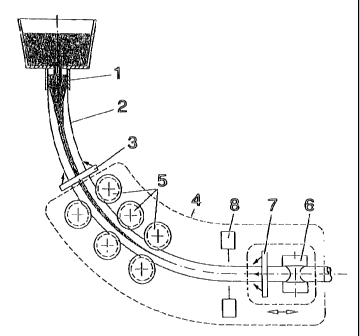
round strands is illustrated in the drawing and described below.
1 designates the vertical, round strand-casting machine with
h.orizontal run-out, in the mold of which a round billet with a
diameter in the range of 90-300 mm is cast and then withdrawn
from below. In the curved stand of the plant, the round billet 2
is deflected from the vertical to the horizontal direction and
treated in the manner according to the invention. For this pur-
pose, the round billet, which is still liquid on the inside, is
first descaled in a primary descaling device 3 and simultaneously
cooled to create the surface conditions for the following roll
deformation of the round billet. This deformation occurs in a
multi-stand rolling unit 4 consisting of three successive
horizontal roll stands 5, each with false-.round grooving
consisting of two radii, with a continuous transition between
them. The last of the three horizontal roll stands can be
screwed down under load and is provided with a roll gap control
system, which cooperates with the measuring device 8 for the
height and width of the round billet. It can be seen that the
tip of the liquid crater ends just behind the last horizontal
roll stand 5 of the rolling unit 4. In the area where the round
billet 2 is known to have solidified with certainty all the way
through, a final rolling of the round billet 2 occurs in the
vertical stand 6, after a secondary descaling at 7. This
vertical stand 6 can be shifted in the direction of the arrow in
order to adjust the deformation point in relationship to the tip
of the liquid crater of the round billet 2 in such a way that the
deformation always occurs in the solidified region of the round
billet 2. The position of the tip of the liquid crater can vary
depending on the casting speed, the material, and the dimensions
of the round billet 2. In this case, the vertical stand 6 can be
moved in the casting direction or in the opposite direction; the
casting speed can be adjusted appropriately; or possibly the
8
06/20/01 WED 11:19 FAX 1212 972 5487 CA 02356609 2001 o6 21 ET AL [a 011
vertical stand 6 can be shifted and the casting speed adjusted in
combination.
9