Note: Descriptions are shown in the official language in which they were submitted.
CA 02356659 2001-06-20
WO 00/39010 PCT/EP99/10101
1
Device for conveying flat objects between processing equipment items
Description
The invention relates to a device for conveying flat objects, held vertically,
at high
speed along one of their long dimensions and one after another, between
processing
equipment items in an installation, and in particular for conveying mail
envelopes of
varying size in a postal sorting installation.
The conveying of flat objects, one after another, between two items of
processing
equipment, is currently achieved using an endless belt on which the flat
objects are
placed in succession. However, such conveying is unsatisfactory when the
objects
have to be presented vertically, for example for direct reading at a sorting
station, and
an arrangement for changing the orientation of the objects has then to be
provided.
Another known solution for conveying flat objects one after another is
obtained by
using a motorized corridor between the processing equipment items that are to
be
connected. This corridor comprises a base belt on which the flat objects are
placed
edge-on, because of their weight, and two lateral belts between which the flat
objects
pass in succession in order to be conveyed. The mechanical arrangement needed
to
operate a motorized corridor has the drawback of being relatively complicated
and it is
known that this solution is not very appropriate when soft objects are to be
found
among the succession of flat objects, of different sizes, conveyed at high
speed
between processing equipment items.
An alternative version of the solution for conveying flat objects one after
another
mentioned hereinabove envisages holding the flat objects by gripping them
between a
broad lateral belt, which serves as a reference, against which the flat
objects are
pressed, and a narrow lateral press belt. For this, the press belt is pressed
against the
broad reference belt by mobile rotary pulleys spread out along that part of
the
CA 02356659 2001-06-20
WO 00/39010 PCT/EP99/10101
2
conveying path which is followed by both of the belts between two processing
equipment items. Here again, the mechanical arrangement needed has the
drawback
of being relatively complicated and the solution adopted is suited only to a
small range
of differences in thickness between successive flat objects.
In order to overcome these drawbacks, the invention therefore proposes a
device for
conveying flat objects, held vertically, at high speed in a movement along one
of their
long dimensions and one after another, between processing equipment items, and
in
particular for conveying mail envelopes of varying size in a postal sorting
installation.
According to one feature of the invention, the device comprises:
- a stationary baseplate extending from one equipment item to another to allow
the
envelopes, resting on their edge, to slide;
- a broad motorized endless reference belt stretched over a set of vertical
pulleys
mounted on fixed axles and extending, in particular, above the baseplate,
along
the edge of which this belt extends along the conveying path between equipment
items, so as to provide lateral support for the envelopes in a vertical
position;
- a motorized endless press belt mounted on a set of vertical pulleys with
fixed
axles in such a way that it can be pressed against the reference belt along
the
conveying path between equipment items followed by this reference belt, so as
to grip the envelopes introduced between the latter belt and itself at one end
of
the conveying path followed;
- a series of free and elastically deformable wheels, mounted on fixed
vertical
axles along the conveying path between equipment items, so as to come to bear
against the press belt in the zone where the latter presses against the
reference
belt, so as, by elastic deformation, to grip all the envelopes conveyed
appropriately in spite of the differences in thickness there may be between
these
envelopes.
According to one feature of the invention, the wheels are longitudinally
offset with
respect to the pulleys of the set carrying the reference belt along the
conveying path
between equipment items.
CA 02356659 2001-06-20
WO 00/39010 PCT/EP99/10101
3
According to one feature of the invention, the spacing between wheels and
between
pulleys is shorter than the intended spacing between two objects being
conveyed one
after the other.
According to one feature of the invention, at least one fixed guide is mounted
so that it
is parallel, along the conveying path followed by the belts between the
equipment
items, so as to provide support to the upper parts of the envelopes being
conveyed at
least on that side on which these envelopes are gripped by the press belt.
According to one feature of an alternative form of the invention, several
guides are
mounted in parallel at different heights along the conveying path followed by
the belts
between the equipment items, so as to provide support to the upper parts of
the
envelopes being conveyed, according to the height of these envelopes, and at
least on
that side where the press belt grips them.
The invention, its characteristics and its advantages are specified in the
description
which follows in conjunction with the figures mentioned hereinbelow.
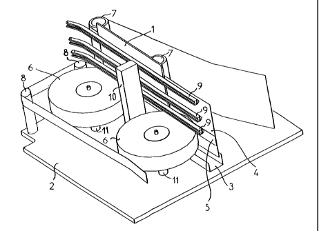
Figure 1 diagrammatically depicts the essential elements of a conveying device
according to the invention, viewed in perspective;
Figure 2 depicts a view from above of the device illustrated in Figure 1.
The conveying device according to the invention, illustrated partially in
Figure 1, is
intended to move flat objects 1, of rectangular appearance and varying
dimensions,
such as postal envelopes, between two object-processing equipment items of an
installation, not depicted. It allows the objects to be conveyed, at high and
constant
speed, in a vertical position and one after another, in a movement along one
of their
two long dimensions.
The envisaged objects are, for example, envelopes, the usual dimensions of
which are
between 140 and 400 millimeters long, 90 and 300 millimeters wide, and between
0.15
and 32 millimeters thick. The may possibly be relatively soft, although in
general they
are more or less rigid.
CA 02356659 2001-06-20
WO 00/39010 PCT/EP99/10101
4
The device according to the invention is, in this instance, assumed to be
mounted on a
mounting plate 2. It essentially comprises a set of elements consisting of a
baseplate
3, a reference belt 4, a press belt 5 and a series of elastically deformable
wheels 6,
some of these elements being depicted only in part in the figures. The
assembly is
designed to extend between the two equipment items of the installation between
which
the flat objects are to be conveyed. The distance between these equipment
items is
not a truly critical factor, but is not usually very long and generally does
not exceed a
few meters. The baseplate 3 is designed to allow the envelopes resting on
their edge
thereon to slide via their lower end as they travel from one equipment item to
the other;
io in this particular instance it is assumed to be of profiled shape with a U-
shaped cross
section.
The reference belt 4 is a motorized fixed-back endless belt mounted in the
conventional way on a set of vertical pulleys. This set includes idler pulleys
such as the
pulleys 7 and drive pulleys, not depicted, and allows the belt to be kept
firmly taut. This
belt provides reference support for the envelopes conveyed along the length of
the
path that these envelopes take between the equipment item transmitting them
and the
one receiving them. It is arranged vertically above the baseplate, along the
edge of
which it extends along the aforementioned path between equipment items. This
reference belt is preferably relatively wide so as to provide the flat objects
with good
support of one of their two large faces and so as to keep these objects
vertical while
they are being conveyed. This width is, for example, of the order of 200
millimeters in
the case of the objects of the aforementioned dimensions.
The press belt 5 is intended to keep the flat objects pressed against the
reference belt
while they are being conveyed. This is a motorized endless belt mounted over a
set
including vertical pulleys such as 8 and 8', which may or may not be driven,
around
which it is stretched. This belt, which is preferably narrow, presses against
the
reference belt along the aforementioned path between equipment items and above
the
baseplate.
The press belt 5 is pressed against the reference belt 4, for example, in the
central
lower part of this reference belt, as shown in Figure 1. This is achieved by
the action of
a series of elastically deformable free wheels 6 mounted on fixed and vertical
axles 11.
Each of these wheels presses against the press belt in the zone where this
belt
_. . _. ~.._._._..______..=.._._
- - - -- --- ------
CA 02356659 2001-06-20
WO 00/39010 PCT/EP99/10101
presses against the reference belt on the other side of this press belt with
respect to
this reference belt. The wheels 6 are made, in a way known to the person
skilled in the
art, to absorb, by elastic deformation, the differences in thickness there are
likely to be
between the flat objects and more particularly between two flat objects placed
one
5 after the other and in order to remain pressed against the press belt
constantly even
when there is no flat object between the two belts at their respective
locations.
These wheels are, for example, spoked wheels, of the low-pressure type, made
of
polyurethane, of the type produced by the company COURBIS, these wheels
having,
for example, a diameter of the order of 250 millimeters and width of 50
millimeters.
In a preferred embodiment, the wheels 6 are longitudinally offset from the
pulleys 7
along the path between equipment items traveled by the two belts 4 and 5
pressed
against each other. The spacings of the wheels 6 and of the pulleys 7 is
preferably
chosen to be slightly shorter than the intended spacing between two objets
placed one
after the other so as to guarantee that all objects conveyed between the two
belts 4
and 5 will be gripped correctly.
It is also intended that there be mounted at least one fixed guide 9, parallel
to the path
followed by the two belts between the equipment items, to act as a support for
the
upper part of the envelopes conveyed when the envelopes tend to bend over on
the
side on which they are least supported heightwise during conveying, this side
being the
side where these envelopes are gripped by the narrow press belt.
In the embodiment proposed, there are three parallel guides 9 borne by posts
10 fixed
to the mounting plate 2, to provide support for envelopes of different
heights. This or
these guides, of the rail type, are mounted in such a way that they extend
along the
path along which the objects are conveyed by the belts at a distance from the
reference belt 4 which is slightly greater than the maximum envisaged
thickness of an
object.
The device therefore allows a succession of flat objects presented vertically
to be
conveyed along one of their two long dimensions, to an inlet of the device
situated, for
example, between the two adjacent pulleys 7 and 8 visible at the left-hand end
of the
device as depicted in Figure 2. Each flat object 1 is inserted between the two
belts 4
CA 02356659 2001-06-20
WO 00/39010 PCT/EP99/10101
6
and 5 between which it is immediately gripped, its passage past one of the
wheels 6
causing temporary crushing of this wheel because of its thickness, without
significant
deformation of the reference belt 4, because of the tension therein. At the
same time
as being inserted between the belts 4 and 5, each flat object becomes inserted
between the reference belt 4 and one and/or other of the guides 9, depending
on the
height by which it projects above this belt. It therefore moves along resting
along one
of the guides as it is conveyed from one equipment item to another, if it does
not have
enough rigidity to remain vertical by itself.
The device according to the invention has the advantage of corresponding to a
simple
assembly which is produced using a small number of standard components mounted
statically. This assembly also has the advantage of not requiring
articulations between
moving parts. It can therefore be produced economically and exhibit great
reliability.