Language selection

Search

Patent 2356848 Summary

Third-party information liability

Some of the information on this Web page has been provided by external sources. The Government of Canada is not responsible for the accuracy, reliability or currency of the information supplied by external sources. Users wishing to rely upon this information should consult directly with the source of the information. Content provided by external sources is not subject to official languages, privacy and accessibility requirements.

Claims and Abstract availability

Any discrepancies in the text and image of the Claims and Abstract are due to differing posting times. Text of the Claims and Abstract are posted:

  • At the time the application is open to public inspection;
  • At the time of issue of the patent (grant).
(12) Patent: (11) CA 2356848
(54) English Title: COLLISION-RESISTANT DOUBLE-SKIN STRUCTURE
(54) French Title: STRUCTURE A DOUBLE REVETEMENT RESISTANT AUX CHOCS
Status: Term Expired - Post Grant Beyond Limit
Bibliographic Data
(51) International Patent Classification (IPC):
  • B63B 43/18 (2006.01)
  • B63B 03/20 (2006.01)
  • B63B 03/62 (2006.01)
(72) Inventors :
  • LUDOLPHIJ, JOHANNES WILHELMUS LUBBERTUS
(73) Owners :
  • SCHELDE MARITIEM B.V.
(71) Applicants :
  • SCHELDE MARITIEM B.V.
(74) Agent: MCCARTHY TETRAULT LLP
(74) Associate agent:
(45) Issued: 2008-07-29
(86) PCT Filing Date: 1999-12-10
(87) Open to Public Inspection: 2000-06-22
Examination requested: 2004-11-12
Availability of licence: N/A
Dedicated to the Public: N/A
(25) Language of filing: English

Patent Cooperation Treaty (PCT): Yes
(86) PCT Filing Number: PCT/NL1999/000757
(87) International Publication Number: NL1999000757
(85) National Entry: 2001-06-11

(30) Application Priority Data:
Application No. Country/Territory Date
1010794 (Netherlands (Kingdom of the)) 1998-12-11

Abstracts

English Abstract


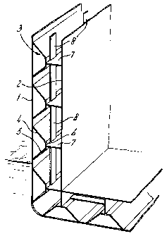
An impact-resistant double-skinned structure, such as a
double-skinned ship's side, comprises an outer skin (1) and an
inner skin (2). A series of channels (3) made of a ductile material
and positioned alongside or above one another are attached by
the tips of their side walls (4, 5) to the inner surface of the
outer skin (1) of the structure. The base (6) of each channel is
connected at least by a stringer (7), essentially perpendicular to
said base, to the inner skin (1) of the structure or a construction
attached thereto.


French Abstract

La présente invention concerne une structure à double revêtement résistant aux chocs, comme par exemple la paroi à double revêtement d'un navire, et comprenant un revêtement extérieur (1) et un revêtement intérieur (2). Une série de canaux (3), faits d'une matière ductile et disposés côte à côte ou les uns au-dessus des autres, sont rattachés par les extrémités de leurs parois latérales (4, 5) à la surface intérieure du revêtement extérieur (1) de la structure. La base (6) de chaque canal est reliée au moins par une bande de renforcement (7), essentiellement perpendiculaire à ladite base, au revêtement intérieur (1) de la structure ou à une construction rattachée.

Claims

Note: Claims are shown in the official language in which they were submitted.


4
Claims
1. A collision-resistant double-skinned structure for a hull of a ship, said
structure
comprising:
an outer skin;
an inner skin; and
a series of channels made of a ductile material and positioned alongside or
above one
another, said series of channels being attached by their tips of their side
walls to an
inner surface of said outer skin of said structure and a base of each channel
being
connected at least by a stringer, essentially perpendicular to said base, to
said inner
skin or to a construction attached thereto.
2. The structure as claimed in Claim 1, wherein bases of successive channels
of said
series of channels are joined to one another by means of strips.
3. The structure as claimed in Claim 1 or 2, wherein said side walls which are
directed
towards said inner surface of said outer skin make an angle .alpha. of less
than 90° with said outer
skin.
4. The structure as claimed in any one of Claims 1, 2 or 3, wherein additional
channels
are also arranged on an inner surface of said inner skin, said additional
channels are attached
by tips of their side walls to said inner surface, and said stringers extend
between said
channels arranged on said outer skin and said additional channels arranged on
said inner skin.
5. The structure as claimed in any one of Claims 1 to 4, wherein said series
of channels
are joined to one another to form a corrugated plate.
6. The structure as claimed in any one of Claims 1 to 5, wherein the structure
is made of
steel 37.

Description

Note: Descriptions are shown in the official language in which they were submitted.


CA 02356848 2007-07-19
Title: Collision-resistant double-skin structure
Field of Invention
The invention relates to a collision-resistant double-skin structure, such as
a double-skinned
ship's side.
Backizround
If oil tankers are involved in collisions or run aground this can result in
severe pollution of
the environment if the hull is holed. The same applies in respect of chemical
tankers on
inland waterways. Existing ferries run the risk of being holed in the side in
the event of a
collision, which under certain circumstances gives rise to an appreciable
safety risk for the
passengers. It is thus apparent that improvement in the impact and explosion
resistance of
double-skinned structures of ships, offshore installations and facilities for
the processing
industry is extremely important.
Summary of Invention
An aspect of the invention is to provide a substantially improved collision-
and explosion-
resistant double-skinned structure. According to the invention, to this end
the structure
comprises: a series of channels made of a ductile material and positioned
alongside or above
one another, which channels are attached by the tips of their side walls to
the inner surface of
the outer skin of the structure, the base of each channel being connected at
least by a stringer,
essentially perpendicular to said base, to the inner skin of the structure or
to a construction
attached thereto.
The substantially improved resistance to holing is achieved in that in the
event of a collision
the dent manifests itself over a substantial width, the ideal membrane stress
being achieved
and the resistance to holing being maximum.
An even better result is achieved if the bases of successive channels are
joined to one another
by means of strips or a stringer. The strips or the stringer provide for
symmetrical
deformation of both side walls of the channels at the start of the collision.
The strips or the
stringer then break off. Should the strips or the stringer not be present
there is a risk in a
collision of one of the side walls of the channels being deflected
substantially to one side and
the other side wall following the first side wall. This non-symmetrical
displacement of the
side walls of the channels leads to a reduction in the resistance to holing.
:LfcCarthy Tetrault LLP TDO-RED #8378861 v. 2

CA 02356848 2007-07-19
-2-
The intention is that those channel parts or side walls directed towards the
inner surface of the
outer skin of the ship's side make an angle a of less than 90 with said outer
skin.
Individual channels can be used. Instead of this the channels can also be
joined to one
another to form a single corrugated plate.
In the case of a particular structure, channels are also arranged on the inner
surface of the
inner skin, which channels are attached by the tips of the side walls to said
inner surface, and
the said stringers extend between the channels arranged on the outer skin and
the channels
arranged on the inner skin.
The material of the structure should be ductile. Steel 37 proves to be an
excellent material,
but some plastics and materials which have a so-called collapse path, such as
certain
composites and sandwich materials, can also be processed.
In another aspect, a collision-resistant double-skinned structure for a hull
of a ship is
provided. The structure comprises: an outer skin; an inner skin; and a series
of channels
made of a ductile material and positioned alongside or above one another. The
channels are
attached by their tips of their side walls to an inner surface of the outer
skin of the structure
and a base of each channel is connected at least by a stringer, essentially
perpendicular to the
base, to the inner skin or to a construction attached thereto.
In the structure, bases of successive channels of the series of channels may
be joined to one
another by means of strips.
In the structure, the side walls which are directed towards the inner surface
of the outer skin
may inake an angle a of less than 90 with the outer skin.
In the structure, additional channels may also arranged on an inner surface of
the inner skin.
The additional channels may be attached by tips of their side walls to the
inner surface, and
the stringers may extend between the channels arranged on the outer skin and
the additional
channels arranged on the inner skin.
In the structure, the series of channels may be joined to one another to form
a corrugated
plate.
In the structure, the structure may be made of steel 37.
Brief Description of Drawinj!s
The invention will now be explained on the basis of the description of the
figures.
McCarthy Tetrault LLP TDO-RED #8378861 v. 2

CA 02356848 2007-07-19
-3-
Figure 1 shows a perspective view of part of a double-skinned ship's side
according to a first
embodiment of the invention.
Figure 2 shows a vertical section of the ship's side according to Figure 1.
Figure 3 shows a vertical section of the ship's side according to Figure 1
after a severe
collision.
Figure 4 shows a vertical section of a second embodiment of a ship's side.
Figure 5 shows a vertical section of a third embodiment of a ship's side.
Detailed Description of Embodiments
The double-skinned structure shown in Figures 1 and 2 comprises an outer skin
1 and an
inner skin 2. Channels 3 are attached to the inner surface of the outer skin
I. The channels
have two side walls 4, 5, which make an angle of 45 with the outer skin 1,
and a base 6,
which joins the two side walls 4 and 5 to one another. A stringer 7 extends
from the base 6 of
the channels, perpendicularly to said base, to the inner surface of the inner
skin 2. The bases
6 of the successive channels are joined to one another by strips 8. The
material of said parts 1
to 8 is ductile and consists, for example, of steel 37.
Figure 3 shows the case where a section of double-skinned ship's side
according to Figures 1
and 2 has been subjected to a severe collision. The outer skin I has moved
somewhat
inwards and the side walls 4 and 5 of the channel have been bent. The stringer
7 has become
curved. No holes are produced during the collision. In fact, there is question
of a membrane
stress.
In the embodiment according to Figure 4 the channels are of semi-cylindrical
construction.
Figure 5 shows an embodiment in which channels 3 are attached both to the
inner surface of
the outer skin and to the inner surface of the inner skin and the stringers 7
extend between the
bases of the channels positioned opposite one another.
The structure according to the invention employed in a ship having a double-
skinned hull has
now been tested and the result was astonishing. The energy absorbed by the
structure in a
severe collision with a ram ship was found to be so effective that the outer
skin exhibited
shallow denting over a large surface (this skin behaved as a membrane) and
there was no
holing.
McCarthy Tetrault LLP TDO-RED #8378861 v. 2

Representative Drawing
A single figure which represents the drawing illustrating the invention.
Administrative Status

2024-08-01:As part of the Next Generation Patents (NGP) transition, the Canadian Patents Database (CPD) now contains a more detailed Event History, which replicates the Event Log of our new back-office solution.

Please note that "Inactive:" events refers to events no longer in use in our new back-office solution.

For a clearer understanding of the status of the application/patent presented on this page, the site Disclaimer , as well as the definitions for Patent , Event History , Maintenance Fee  and Payment History  should be consulted.

Event History

Description Date
Inactive: Expired (new Act pat) 2019-12-10
Common Representative Appointed 2019-10-30
Inactive: Late MF processed 2010-12-29
Letter Sent 2010-12-10
Grant by Issuance 2008-07-29
Inactive: Cover page published 2008-07-28
Pre-grant 2008-05-13
Inactive: Final fee received 2008-05-13
Notice of Allowance is Issued 2007-11-19
Letter Sent 2007-11-19
Notice of Allowance is Issued 2007-11-19
Inactive: IPC removed 2007-10-03
Inactive: Approved for allowance (AFA) 2007-09-25
Amendment Received - Voluntary Amendment 2007-07-19
Amendment Received - Voluntary Amendment 2007-06-19
Amendment Received - Voluntary Amendment 2007-02-14
Inactive: S.30(2) Rules - Examiner requisition 2006-08-15
Letter Sent 2004-11-26
Request for Examination Received 2004-11-12
Request for Examination Requirements Determined Compliant 2004-11-12
All Requirements for Examination Determined Compliant 2004-11-12
Letter Sent 2001-11-16
Inactive: Cover page published 2001-10-24
Inactive: Single transfer 2001-10-09
Inactive: Correspondence - Formalities 2001-10-09
Inactive: First IPC assigned 2001-10-02
Inactive: Courtesy letter - Evidence 2001-09-25
Inactive: Notice - National entry - No RFE 2001-09-21
Application Received - PCT 2001-09-20
Application Published (Open to Public Inspection) 2000-06-22

Abandonment History

There is no abandonment history.

Maintenance Fee

The last payment was received on 2007-10-15

Note : If the full payment has not been received on or before the date indicated, a further fee may be required which may be one of the following

  • the reinstatement fee;
  • the late payment fee; or
  • additional fee to reverse deemed expiry.

Patent fees are adjusted on the 1st of January every year. The amounts above are the current amounts if received by December 31 of the current year.
Please refer to the CIPO Patent Fees web page to see all current fee amounts.

Owners on Record

Note: Records showing the ownership history in alphabetical order.

Current Owners on Record
SCHELDE MARITIEM B.V.
Past Owners on Record
JOHANNES WILHELMUS LUBBERTUS LUDOLPHIJ
Past Owners that do not appear in the "Owners on Record" listing will appear in other documentation within the application.
Documents

To view selected files, please enter reCAPTCHA code :


To view images, click a link in the Document Description column. To download the documents, select one or more checkboxes in the first column and then click the "Download Selected in PDF format (Zip Archive)" or the "Download Selected as Single PDF" button.

List of published and non-published patent-specific documents on the CPD .

If you have any difficulty accessing content, you can call the Client Service Centre at 1-866-997-1936 or send them an e-mail at CIPO Client Service Centre.


Document
Description 
Date
(yyyy-mm-dd) 
Number of pages   Size of Image (KB) 
Representative drawing 2001-10-11 1 9
Abstract 2001-06-10 4 165
Abstract 2001-06-10 1 61
Description 2001-06-10 3 138
Drawings 2001-06-10 1 30
Claims 2001-06-10 1 40
Claims 2007-02-13 1 31
Claims 2007-06-18 1 32
Description 2007-07-18 3 139
Representative drawing 2008-07-14 1 11
Notice of National Entry 2001-09-20 1 210
Courtesy - Certificate of registration (related document(s)) 2001-11-15 1 113
Reminder - Request for Examination 2004-08-10 1 117
Acknowledgement of Request for Examination 2004-11-25 1 177
Commissioner's Notice - Application Found Allowable 2007-11-18 1 164
Maintenance Fee Notice 2011-01-12 1 171
Late Payment Acknowledgement 2011-01-12 1 164
Correspondence 2001-09-20 1 25
PCT 2001-06-10 9 337
Correspondence 2001-10-08 2 64
Fees 2003-09-18 1 26
Fees 2002-10-09 1 38
Fees 2004-10-11 1 28
Fees 2005-10-18 1 25
Fees 2006-11-28 1 24
Fees 2007-10-14 1 27
Correspondence 2008-05-12 1 32