Note: Descriptions are shown in the official language in which they were submitted.
...
CA 02356920 2002-05-17
HYDROCONVERSION PROCESS USING BUI.K GROUI' V111/GROUP
VIB CATALYSTS
FIELD OF THE INVENTION
This invention relates to the hydroprocessing of petroleum and chemical
feedstocks using bulk Group VIIIJGroup VIB catalysts. Preferred catalysts
include those comprised of Ni-Mo-W.
BACKGROUND OF THE INVENTION
As the supply of low sulfur, low nitrogen crudes decrease; refineries are
processing crudes with greater sulfur and nitrogen contents at the same time
that
environmental regulations are mandating lower levels of these heteroatoms in
products. Consequently, a need exists for increasingly efficient
desulfurization
and denitrogenation catalysts.
In one approach, a family of compounds, related to hydrotalcites, e.g.,
ammonium nickel molybdates, has been prepared. Whereas X-ray diffraction
analysis has shown that hydrotalcites are composed of layered phases with
positively charged sheets and exchangeable anions located in the galleries
between
the sheets, the related ammonium nickel molybdate phase has molybdate anions
in
interlayer galleries bonded to nickel oxyhydroxide sheets. See, for example,
Levin, D., Soled, S. L., and Ying, J. Y., Crystal Structure of an Ammonium
Nickel
Molvbdate prepared by Chemical Precipitation, Inorganic Chemistry, Vol. 35.
No.
14, p. 4191-4197 (1996). The preparation of such materials also has been
reponed
by Teichner and Astier. Appl. Catal. 72. 321-29 (1991); Ann. Chim. Fr. 12, 3
37-
CA 02356920 2001-06-27
WO 00/42119 PCT/US00/01009
- 2 -
-I3 (1987), and C. R. Acad. Sci. 304 (11), t'i 1 1, 563-6 (1987) and
Vlazzocchia, Solid
State Ionics, 63-65 (1993) 731-35.
Now, when molybdenum is partially substituted for by tungsten, an
amorphous phase is produced which upon decomposition and, preferably,
sulfidation, provides enhanced hydrodenitrogenation (HDN) catalyst activity
relative to the unsubstituted (Ni-Mo) phase.
SUMMARY OF THE INVENTION
In accordance with this invention there is provided a process for
hydroprocessing a hydrocarbon feedstock, which process comprises contacting
said feedstock, at hydroprocessing conditions, with a bulk catalyst comprised
of at
least one Group VIII metal and two Group VIB metals, which catalyst comprises
a
bulk metal catalyst containing non-noble metal Group V[II molybdate in which
at
least a portion but less than all of the molybdenum is replaced by tungsten.
The
hydroprocessing process is selected from at least one of hydrodesulfurization,
hydrodenitrogenation, hydrodemetallation, hydrodearomatization,
hydroisomerization, hvdrodewaxing, hydrotreating, hydrofining and
hydrocracking.
In a specific embodiment of the invention, there is provided a process for
selectively hydroconverting a raffinate produced from solvent refining a
lubricating oil feedstock which comprises:
(a) conducting the lubricating oil feedstock to a solvent extraction zone
and separating therefrom an aromatics rich extract and a paraffins
rich raffinate;
CA 02356920 2001-06-27
WO 00/42119 PCT/US00/01009
-z-
(b) stripping the raffinate of solvent to producc a raffinatc f'ecd having a
dewaxed oil viscosity index from about 80 to about 105 and a final
boiling point of no greater than about 650 C;
(c) passing the rafffinate feed to a first hydroconversion zone and
processing the raffinate feed in the presence of a bulk metal catalyst
under hydroconversion conditions wherein the bulk metal catalyst
comprises a Group VIII non-noble metal molybdate in which at least
a portion but less than all of the molybdenum is replaced by tungsten
to produce a first hydroconverted raffinate; and
(d) passing the first hydroconverted raffinate to a second reaction zone
and conducting cold hydrofinishing of the first hydroconverted
raffinate in the presence of a hydrofinishing catalyst under cold
hydrofinishing conditions.
In another embodiment, there is provided a process for selectively
hydroconverting a raffinate produced from solvent refining a lubricating oil
feedstock which comprises:
(a) conducting the lubricating oii feedstock to a solvent extraction zone
and separating therefrom an aromatics rich extract and a paraffins
rich raffinate;
(b) stripping the raffinate of solvent to produce a raffinate feed having a
dewaxed oil viscosity index from about 80 to about 105 and a final
boiling point of no greater than about 650 C;
(c) passing the raffinate feed to a first hydroconversion zone and
processing the raffinate feed in the presence of a bulk metal catalyst
under hydroconversion conditions wherein the bulk metal catalyst
comprises a non-noble metal Group VIII molybdate in which at least
CA 02356920 2001-06-27
WO 00/42119 PCT/US00/01009
_~.
a portion but less than all of the molybdcnum is replaced by tungsten
to produce a first hydroconverted raffinate;
(d) passing the hydroconverted rafftnate from the first hydroconversion
zone to a second hydroconversion zone and processing the
hydroconverted raffinate in the presence of a hydroconversion
catalyst under hydroconversion conditions to produce a second
hydroconverted raffinate;
(e) passing the second hydroconverted raffinate to a hydrofinishing
reaction zone and conducting cold hydrofinishing of the second
hydroconverted raffinate in the presence of a hydrofinishing catalyst
under cold hydrofinishing conditions.
In yet another embodiment there is provided a process for selectively
hydroconverting a raffinate produced from solvent refining a lubricating oil
feedstock which comprises:
(a) conducting the lubricating oil feedstock to a solvent extraction zone
and separating therefrom an aromatics rich extract and a paraffins
rich raffinate;
(b) stripping the raffinate of solvent to produce a raffinate feed having a
dewaxed oil viscosity index from about 80 to about 105 and a final
boiling point of no greater than about 650 C;
(c) passing the raffinate feed to a first hydroconversion zone and
processing the raffinate feed in the presence of a hydroconversion
catalyst under hydroconversion conditions to produce a first
hydroconverted raffinate;
(d) passing the hydroconverted raffinate from the first hydroconversion
zone to a second hydroconversion zone and processing the
CA 02356920 2001-06-27
WO 00/42119 PCTIUSOO/01009
_;.
hydroconverted raffinate in the presence of a bulk metal catalyst
under hydroconversion conditions wherein the bulk metal catalyst
comprises a non-noble metal Group VIII molybdate in which at least
a portion but less than all of the molybdenum is replaced by tungsten
to produce a second hydroconverted raffinate;
(e) passing the second hydroconverted raffinate to a hydrofinishing
reaction zone and conducting cold hydrofinishing of the second
hydroconverted raffinate in the presence of a hydrofinishing catalyst
under cold hydrofinishing conditions.
In another embodiment of the present invention the catalyst composition is
prepared by a process which comprises contacting the Group VIII non-noble
metal
component with the Group VIB metal components in the presence of a protic
liquid wherein during contacting not all of the Group VIB and/or Group VIII
non-
noble metals are in solution.
The preferred catalyst composition of the present invention can be further
described as a bulk mixed metal oxide which is preferably sulfided prior to
use,
and which is represented by the formula:
(X)n (Mo)~ (W)d OZ
wherein X is non-noble Group VIII metal, preferably Ni or Co, especially Ni,
the
molar ratio of b: (c+d) is 0.5/1 to 3/1, preferably 0.75/1 to 1.5/1, more
preferably
0.75/1 to 1.25/1;
The molar ratio of c:d is preferably >0.01/1, more preferably >0.1/1, still
more preferably 1/10 to 10/1, still more preferably 1/3 to 3/ 1, most
preferably
substantially equimolar amounts of Mo and W. e.g., 2.'3 to 3112; and z = [2b +
6
(c+d)1/2.
CA 02356920 2001-06-27
WO 00/42119 PCT/US00/01009
-6-
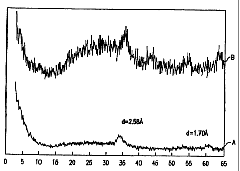
The essentially amorphous material has a unique X-ray diffraction pattern
showing crystalline peaks at d = 2.53 Angstroms and d = 1.70 Angstroms.
The mixed metal oxide is readily produced by the decomposition of a
precursor having the formula:
(NH4). (X)b (Mo), (W)d O:
wherein the molar-ratio of a:b is <_ 1.0/l, preferably 0-i; and X, b, c, and
d, are as
defined above, and z=[a + 2b + 6 (c+d)]/2. The precursor has similar peaks at
d
= 2.53 and 1.70 Angstroms.
Decomposition of the precursor may be effected at elevated temperatures,
e.g., temperatures of at least about 300 C, preferably about 300-450 C, in a
suitable atmosphere, e.g., inerts such as nitrogen, argon, or steam, until
decomposition is substantially complete, i.e., the ammonium is substantially
completely driven off. Substantially complete decomposition can be readily
established by thermogravimetric analysis (TGA), i.e., flattening of the
weight
change curve.
BRIEF DESCRIPTION OF DRAWINGS
Figure 1 is the X-ray diffraction pattern of a NH4Nii.;vioO.5WO; compound
prepared by boiling precipitation before calcining (Curve A) and after
calcining at
400 C (Curve B). Note that the patterns for both the precursor and the
CA 02356920 2001-06-27
WO 00/42119 PCT/US00/01009
7-
eiecomposition product of the precursor are quite similar with the two peaks
at
essentially the same place. The ordinate is relativc intensity; the abscissa
is two
theta (degrees).
Figure 2 shows the X-ray diffraction patterns, by CuKa radiation
(a,=l .5405A), of NH4-Ni-Moj.x-Wx-O precursors wherein curve A is Mo0.9W0.1 ,
curve B is Mo0.7W0.3, curve C is Mo0.5W0.5, curve D is Mo0.3W0.7, curve E is
MoO.I W0.9, and curve F is MoOW 1. The ordinate and abscissa are as described
for Figure 1.
PREFERRED EMBODIMENTS
The catalyst composition according to the invention can be used in virtually
all hydroprocessing processes to treat a plurality of feeds under wide-ranging
reaction conditions such as temperatures of from 200 to 450 C, hydrogen
pressures of from 5 to 300 bar, liquid hourly space velocities of from 0.05 to
10 h-'
and hydrogen treat gas rates of from 35.6 to 1780 m3/m3 (200 to 10000 SCF/B).
The term "hydroprocessing" encompasses all processes in which a hydrocarbon
feed is reacted with hydrogen at the temperatures and pressures noted above,
and
include hydrogenation, hydrotreating, hydrodesulfurization,
hydrodenitrogenation,
hydrodemetallation, hydrodearomatization, hydroisomerization, hydrodewaxing,
and hydrocracking including selective hydrocracking. Depending on the type of
hydroprocessing and the reaction conditions, the products of hydroprocessing
may
show improved viscosities, viscosity indices, saturates content, low
temperature
properties, volatilities and depolarization. Feeds for hydroprocessing include
reduced crudes, hydrocrackates, raffinates, hydrotreated oils, atmospheric and
vacuum gas oils, coker gas oils, atmospheric and vacuum resids, deasphalted
oils,
dewaxed oils, slack waxes, Fischer-Tropsch waxes and mixtures thereot: It is
to
be understood that hydroprocessing of the present invention can be practiced
in
one or more reaction zones and can be practiced in either countercurrent flow
or
CA 02356920 2001-06-27
WO 00/42119 PCT/USOO/01009
.g.
cocurrent flow mode. Bv countercurrent flow mode we mean a process mode
wherein the feedstrcam flows countercurrent to the flow of hydrogen-containing
trcat gas.
The catalyst composition of the invention is particularly suitable for
hydrotreating the hydrocarbon feeds suitable for hydroprocessing as noted
above.
Examples of hydrotreating include hydrogenation of unsaturates,
hydrodesulfurization, hydrodenitrogenation, hydrodearomatization and mild
hydrocracking. Conventional hydrotreating conditions include temperatures of
from 250 to 450 C, hydrogen pressures of from 5 to 250 bar, liquid hourly
space
velocities of from 0.1 to 10 h"', and hydrogen treat gas rates of from 90 to
1780
m3/m3 (500 to 10000 SCF/B). The hydrotreating processes using the catalyst
according to the invention may be particularly suitable for making lubricating
oil
basestocks meeting Group II or Group III base oil requirements.
A wide range of petroleum and chemical feedstocks can be hydroprocessed
in accordance with the present invention. Suitable feedstocks range from the
relatively light distillate fractions up to high boiling stocks such as whole
crude
petroleum, reduced crudes, vacuum tower residua, propane deasphalted residua,
e.g., brightstock, cycle oils, FCC tower bottoms, gas oils including coker gas
oils
and vacuum gas oils, deasphalted residua and other heavy oils. The feedstock
will
normally be a C,o+ feedstock, since light oils will usually be free of
significant
quantities of waxy components. However, the process is also particularly
useful
with waxy distillate stocks, such as gas oils, kerosenes, jet fuels,
lubricating oil
stocks, heating oils, hydrotreated oil stock, furfural-extracted lubricating
oil stock
and other distillate fractions whose pour point and viscosity properties need
to be
maintained within certain specification limits. Lubricating oil stocks, for
example,
will generally boil above 230 C and more usually above 315 C. For purposes of
this invention, lubricating oil or lube oil is that part of the hydrocarbon
feedstock
CA 02356920 2001-06-27
WO 00/42119 PCT/US00/01009
-~)-
having a boiling point of at least 315 C, as determined by ASTM U-1 16() test
method.
This hydroconversion process of the invention produces a lubricating oil
basestock meeting at least 90% saturates and VI of at least 105 by selectiveiy
hydroconverting a raffinate produced from solvent refining a lubricating oil
feedstock. The solvent extraction process selectively dissolves the aromatic
components in an extract phase while leaving the more paraffinic components in
a
raffinate phase. Naphthenes are distributed between the extract and raffinate
phases. Typical solvents for solvent extraction include phenol, furfural and N-
methyl pyrrolidone. By controlling the solvent to oil ratio, extraction
temperature
and method of contacting distillate to be extracted with solvent, one can
control
the degree of separation between the extract and raffinate phases. The
raffinate
from the solvent extraction is preferably under-extracted, i.e., the
extraction is
carried out under conditions such that the raffinate yield is maximized while
still
removing most of ihe lowest quality molecules from the feed. Raffinate yield
may
be maximized by controlling extraction conditions, for example, by lowering
the
solvent to oil treat ratio and/or decreasing the extraction temperature. The
raffinate from the solvent extraction unit is stripped of solvent and then
sent to a
first hydroconversion unit containing a hydroconversion catalyst. This
raffinate
feed has a viscosity index of from about 80 to about 105 and a boiling range
not to
exceed about 650 C, preferably less than 600 C, as determined by ASTM 2887
and a viscosity of from 3 to 15 cSt at 100 C. The stripped raffinate from the
solvent extraction zone may be solvent dewaxed prior to being sent to the
first
hydroconversion unit.
The raffinate feed is passed to a first hydroconversion zone and processed
in the presence of a bulk metal catalyst under hydroconversion conditions
wherein
the bulk metal catalyst comprises nickel molybdate in which at least a portion
but
less than all of the molvbdenum is replaced by tungsten to produce a first
CA 02356920 2001-06-27
WO 00/42119 PCT/US00/01009
- 10-
hvdroconverted raffinate. The hydroconverted raffinate from the tirst
hydroconversion zone may then be passed to a hydrofinishing zone or in the
alternative passed to a second hydroconversion zone and then passed to a
hydrofinishing zone. In the case of two hydroconversion zones, the catalyst in
both
hydroconversion zones may be bulk metal catalyst according to the invention,
or
the bulk metal catalyst may be used in either the first or second
hydroconversion
zones. In the case of two zones where bulk metal catalyst is used in only one
of the
zones, the other catalyst may be a non-bulk metal hydrotreating catalyst.
Hydrotreating catalysts are those containing at least one Group VIB and at
least
one Group VIII metal supported on a refractory metal oxide. The Group VIB
metal
is preferably molybdenum or tungsten and the Group VIII metal is preferably a
non-noble metal such as cobalt or nickel.
The hydroconversion conditions in either the first or second
hydroconversion zones include temperatures of from 300 to 420 "C, hydrogen
pressures of from-300 to 3000 psig (2170 to 20786 kPa), liquid hourly space
velocities of from 0.1 to 10 and hydrogen treat gas rates of from 500 to 5000
scf/B (89 to 890 m3/m3).
The hydroconversion zone(s) are then followed by a hydrotinishing zone.
The hydrofinishing zone corrects product quality properties such as color,
stability
and toxicity. The hydrofinishing zone is characterized as a cold
hydrofinishing
zone with conditions including temperatures of from 250 to 360 "C, hydrogen
pressures of from 300 to 3000 psig (2170 to 20786 kPa), liquid hourly space
velocities of from 0.1 to 10 and hydrogen treat gas rates of from 500 to 5000
scf/B
(89 to 890 m3/m3). The catalyst for the hydrofinishing zone may be either the
bulk
metal catalyst according to the invention or may be a non-bulk metal
hydrotreating
catalyst. Hydrotreating catalysts are those containing at least one Group VIB
and
at least one Group VIII metal supported on a refractory metal oxide. The Group
CA 02356920 2001-06-27
WO 00/42119 PCT/USOO/01009
I1-
VIF3 metal is preferably moi,vbdenum or tungsten and the Group VIII metal is
preferably a non-noble metal such as cobalt or nickel.
The hydrofinishing zone may be prcccdcd by or followed by a dewaxing
zone. The dewaxing may be either catalytic or solvent. Solvent dewaxing may be
accomplished by using a solvent and chilling to crystallize and separate wax
molecules. Typical solvents include propane and ketones. Preferred ketones
include methyi ethyl ketone, methyl isobutyl ketone and mixtures thereof.
Catalytic dewaxing may be accomplished using an 8, 10 or 12 ring molecular
sieve. Preferred molecular sieves include zeolites and silicoaluminophosphates
(SAPOs). 10 ring molecular sieves are preferred including at least one of ZSM-
5,
ZSM-22, ZSM-23, ZSM-35, ZSM-48 ZSM-57, SAPO-11, and SAPO-41.
The high conversion activity shown by the subject bulk metal catalyst has
substantial process advantages such as greater feed flexibility, smaller
reactors,
lower catalyst quantities and greater operator flexibility in product quality
control.
The hydrocarbon feedstocks which are typically subjected to hydrocracking
herein will typically boil at a temperature above 150 C. The feedstocks can
contain a substantial amount of nitrogen, e.g. at least 10 wppm nitrogen, and
even
greater than 500 wppm, in the form of organic nitrogen compounds. The feeds
can
also have a significant sulfur content, ranging from about 0.1 wt.% to 3 wt.%,
or
higher. If desired, the feeds can be treated in a known or conventional manner
to
reduce the sulfur and/or nitrogen content thereof.
For purposes of the present invention where it is desirable to produce a lube
basestock the feed can be a wide variety of wax-containing feedstocks
including
feeds derived from crude oils, shale oils and tar sands as well as synthetic
feeds
such as those derived from the Fischer-Tropsch process. Typical wax-containing
feedstocks for the preparation of lubricating base oils have initial boiling
points of
CA 02356920 2001-06-27
WO 00/42119 PCT/USOO/01009
-12-
about 315 C or higher, and include feeds such as reduced crudes,
hydrocrackates,
raffinates, hydrotreated oils, atmospheric gas oils, vacuum gas oils, coker
gas oils,
atmospheric and vacuum resids, deasphalted oils, slack waxes and Fischer-
Tropsch wax. The feed is preferably a mixture of gas oil from a coker and
vacuum
distillation froin conventional crudes with a maximum boiling point of the
coker
gas oil not to exceed 1050 F. Such feeds may be derived from distillation
towers
(atmospheric and vacuum), hydrocrackers, hydrotreaters and solvent extraction
units, and may have wax contents of up to 50% or more.
Hydroprocessing of the present invention also includes slurry and
ebullating bed hydrotreating processes for the removal of sulfur and nitrogen
compounds and,the hydrogenation of aromatic molecules present in light fossil
fuels such as petroleum mid-distillates. Hydrotreating processes utilizing a
slurry
of dispersed catalysts in admixture with a hydrocarbon oil are generally
known.
For example, U.S. Pat. No. 4,557,821 to Lopez et al discloses hydrotreating a
heavy oil employing a circulating slurry catalyst. Other patents disclosing
slurry
hydrotreating include U.S. Pat. Nos. 3,297,563; 2,912,375; and 2,700,015. The
slurry hydroprocessing process of this invention can be used to treat various
feeds
including mid-distillates from fossil fuels such as light catalytic cycle
cracking oils
(LCCO). Distillates derived from petroleum, coal, bitumen, tar sands, or shale
oil
are likewise suitable feeds. On the other hand, the present process is not
useful for
treating heavy catalytic cracking cycle oils (HCCO), coker gas oils, vacuum
gas
oils (VGO) and heavier resids, which contain several percent 3+ ring
aromatics,
particularly large asphaltenic molecules. When treating heavier resids, excess
catalyst sites are not obtainable, and reactivation of the catalyst by high
temperature denitrogenation is not feasible.
The present invention can also be used to produce white oils. White
mineral oils, called white oils, are colorless, transparent, oily liquids
obtained by
the refining of crude petroleum feedstocks. In the production of white oils,
an
CA 02356920 2001-06-27
WO 00/42119 PCT/US00/01009
- 13-
appropriatc petroleum feedstock is refined to eliminate, as completely as
possible,
oxygen, nitrogen, and sulfur compounds, reactivc hydrocarbons inciuding
aromatics, and any other impurity which would prevent use of the resulting
white
oil in the pharmaccutical or food industry.
The feedstream is contacted at hydroprocessing conditions with a bulk
catalyst containing two Group VIB metals and at least one Group VIII metal,
preferably two Group VIB metals and one non-noble Group VIII metal, more
preferably Ni-Mo-W. The bulk catalyst compositions of the present invention
can
be prepared by a process wherein all of the metal precursor components are in
solution or where not all of the metal components are in solution. That is, a
process which comprises contacting at least one Group VIII non-noble metal
component with the Group VIB metal components in the presence of a protic
liquid wherein during contacting not all of the Group VIB and/or Group VIII
non-
noble metals are in solution.
Process for preparing catalyst wherein not all of the metals are in solution.
Generally, the contacting of the metal components in the presence of the
protic liquid comprises mixing the metal components and subsequently reacting
the resulting mixture. It is essential to the solid route that at least one
metal
components is added at least partly in the solid state during the mixing step
and
that the metal of at least one of the metal components which have been added
at
least partly in the solid state, remains at least partly in the solid state
during tine
mixing and reaction step. "Metal" in this context does not mean the metal in
its
metallic form but present in a metal compound, such as the metal component as
initially applied or as present in the bulk catalyst composition.
Generally, during the mixing step either at least one metal component is
added at least partly in the solid state and at least one metal component is
added in
CA 02356920 2001-06-27
WO 00/42119 PCT/US00/01009
-14-
the solute state, or all metal components are added at least partly in the
solid state,
wherein at least one of the metals of the metal components which are added at
least partly in the solid state remains at least partly in the solid state
during the
entire process of the solid route. That a metal component is added "in the
solute
state" means that the whoie amount of this metal component is added as a
solution
of this metal component in the protic liquid. That a metal component is added
"at
least partly in the solid state" means that at least part of the metal
component is
added as solid metal component and, optionally, another part of the metal
component is added as a solution of this metal component in the protic liquid.
A
typical example is a suspension of a metal component in a protic liquid in
which
the metal is at least partly present as a solid, and optionally partly
dissolved in the
protic liquid.
If during the mixing step at least one metal component is added at least
partly in the solid state and at least one metal component is added in the
solute
state, the following process altematives can be applied: it is possible to
first
prepare a suspension of a metal component in the protic liquid and to add
simultaneously, or one after the other, solutions and/or further suspensions
comprising dissolved and/or suspended metal components in the protic liquid.
It
is also possible to first combine solutions either simultaneously or one after
the
other and to subsequently add further suspensions and optionally solutions
either
simultaneously or one after the other. If during the mixing step, each metal
component is added at least partly in the solid state, it is possible to
prepare
suspensions comprising the metal components and to combine these suspensions
either one after the other or simultaneously. It is also possible to add the
metal
components as such to a suspension or solution of at least one of the metal
components.
CA 02356920 2001-06-27
WO 00/42119 PCT/US00/01009
15-
In all the above-described cases, the suspension comprising a metal
component can be prepared by suspending a preformed metal component in the
protic liquid. However, it is also possible to prcpare the suspension by (co)
precipitating one or more metal components in the protic liquid. '1'he
resulting
suspension can either be applied as such in the process of the solid route,
i.c.
further tnetal components either in solution, slurry or per se are added to
the
resulting suspension, or it can be applied after solid-liquid separation and
optionally re-slurrying of the obtained solid metal component in the protic
liquid.
Further, in all the above cases, instead of a suspension of a metal component,
it is also possible to use a metal component in the wetted or dry state.
Wetted or
dry metal components can be prepared from preformed metal components or by
precipitation as described above and by subsequently partly or completely
removing the protic liquid. However, care must be taken that any protic liquid
is
present during contacting.
It must be noted that the above process alternatives are only some examples
to illustrate the mixing step. Independently from the number of metal
components
that are applied in the solid route, the order of addition is generally not
critical to
the process of this invention.
In one embodiment of the present invention (solid route), one of the metal
components is added at least partly in the solid state and further metal
components
are added in the solute state. For instance, one metal component is added at
least
partly in the solid state and two metal components are added in the solute
state. In
another embodiment, two metal components are added at least partly in the
solid
state and one metal component is added in the solute state. In still another
embodiment, three or more metal components are added at least partly in the
solid
state and no further metal components are added in the solute state.
Generally, the
CA 02356920 2001-06-27
WO 00/42119 PCT/US00/01009
- 16-
number of metal components which are added at least partly in the solid state
and
which are added in the solute state is not criticai to the this invention.
It will be clear that it is, c.g., not suitable to prepare first a solution
comprising all metal components necessary for the preparation of a certain
catalyst
composition and to subsequently coprecipitate these components. Nor is it
suitable for the process for the this invention to add metal components at
least
partly in the solid state and to choose the process conditions, such as
temperature,
pH or amount of protic liquid in such a way, that all added metal components
are
present at least at some stage completely in the solute state. On the
contrary, as
has been set out above, for the solid route, at least the metal of one of the
metal
components that are added at least partly in the solid state must remain in at
least
partly the solid state during the entire process of this invention.
Preferably, at least 1 wt.%, even more preferably at least 10 wt.% and most
preferably at least 15 wt.% of the metal components are in the solid state
during
mixing, based on the total weight of all added metal components, i.e. of all
metai
components employed initially in the solid route, calculated as metal oxides.
When it is desired to obtain a high yield, i.e., a high amount of the bulk
catalyst
composition, the use of metal components of which a high amount remains in the
solid state during contacting is recommended. As in this case, low amounts of
metal components remain solved in the mother liquid, the amount of metal
components ending up in the wastewater during the subsequent solid-liquid
separation is decreased.
If the metals which are added at least partly in the solid state are added as
a
suspension, the amount of solid metals in this suspension can be determined by
filtration of the suspension at the conditions which are applied during the
mixing
step (temperature, pH, pressure, amount of liquid) in such a way that all
solid
CA 02356920 2001-06-27
WO 00/42119 PCT/US00/01009
- 17-
material contained in the suspension is collected as solid filter cake. From
the
weight of the solid and dried filter cake, the weight of the solid metais can
be
determined by standard techniques. If several suspensions are applied, the
weight
of the solid metal components contained in thcse suspcnsions must be added to
each other to give the total amount of solid metal components, calculated as
metal
oxides. Of course, if apart from solid metal components further solid
components
such as a solid binder are present in the filter cake, the weight of this
solid and
dried binder must be subtracted from the weight of the metal components in the
solid and dried filter cake. In this case, standard techniques such as atomic
absorption spectroscopy (AAS), XRF, wet chemical analysis, or ICP can
determine the amount of solid metals in the filter cake.
If the metal component, which is added at least partly in the solid state, is
added in the wetted or dry state, a filtration generally is not possible. In
this case,
the weight of the solid metal component is considered equal to the weight of
the
corresponding initially employed metal component. The total weight of all
metal
components is the amount of all metals that are initially employed as metal
components, calculated as metal oxides.
It has been found that the morphology and texture of the metal component,
which remains at least partly in the solid state during contacting, may
determine
the morphology and texture of the bulk catalyst composition. Consequently,
e.g.,
by applying metal component particles with a certain morphology and texture,
the
morphology and texture of the resulting bulk catalyst particles can be
controlled.
"Morphology and texture" in the sense of the present invention refer to pore
volume, pore size distribution, surface area, particle form, and particle
size.
To obtain a bulk catalyst composition with high catalytic activity, it is
therefore preferred that the metal components, which are at least partly in
the solid
CA 02356920 2001-06-27
WO 00/42119 PCT/US00/01009
- 18-
statc during contacting, arc porous mctal componcnts. It is dcsircd that the
total
pore volume and pore sizc distribution of these metal components is
approximately the same as those of conventional hydrotreating catalysts.
Conventional hvdrotrcating cztaivsts generally have a porc volume ot'().U5 - 5
mI/g, preferably of 0.1 --3 ml/g, more preferably of 0.1 - 3 ml/g and most
preferably of 0.1 - 2 ml/g determined by nitrogen adsorption. Pores with a
diameter smaller than I nm are generally not present in conventional
hydrotreating
catalysts. Further, conventional hydrotreating catalysts have generally a
surface
area of at least 10 m2/g and more preferably of at least 50 m2/g and most
preferably of at least 100 m2/g, determined VIB the B.E.T. method. For
instance,
nickel carbonate can be chosen which has a total pore volume of 0.19 - 0.39
mi/g
and preferably of 0.24 - 0.35 ml/g determined by nitrogen adsorption and a
surface
area of 150 - 400 m2/g and more preferably of 200 - 370 m2/g determined by the
B.E.T. method. Furthermore these metal components should have a median
particle diameter of at least 50 nm, more preferably at least 100 nm, and
preferably
not more than 5000 m and more preferably not more than 3000 m. Even more
preferably, the median particle diameter lies in the range of 0.1 - 50 m and
most
preferably in the range of 0.5 - 50 m. For instance, by choosing a metal
component which is added at least partly in the solid state and which has a
large
median particle diameter, the other metal components will only react with the
outer layer of the large metal component particle. In this case, so-called
"core-shell" structured bulk catalyst particles are obtained.
An appropriate morphology and texture of the metal component can either
be achieved by applying suitable preformed metal components or by preparing
these metal components by the above-described precipitation under such
conditions that a suitable morphology and texture is obtained. A proper
selection
of appropriate precipitation conditions can be made by routine
experimentation.
CA 02356920 2001-06-27
WO 00/42119 PCT/US00/01009
- 19-
As has been set out above, to retain the morphology and texture of the
metal components which are added at lcast partly in the solid state, it is
essential
that the metal of the metal component at least partly remains in the solid
state
during the whole process of this solid route. It is noted again that it is
essential
that in no case should the amount of solid metals during the process of the
solid
route becomes zero. The presence of solid metal comprising particles can
easily
be detected by visual inspection at least if the diameter of the solid
particles in
which the metals are comprised is larger than the wavelength of visible light.
Of
course, methods such as quasi-elastic light scattering (QELS) or near forward
scattering whichare known to the skilled person can also be used to ensure
that in
no point in time of the process of the solid route, all metals are in the
solute state.
Without wishing to be bound by any theory, it is believed that during the
process of the solid route, the metal components, which are added during the
mixing step at least partly, react with each other. The protic liquid is
responsible
for the transport of dissolved metal components. Due to this transport, the
metal
components come into contact with each other and can react. It is believed
that
this reaction can even take place if all metal components are virtually
completely
in the solid state. Due to the presence of the protic liquid, a small fraction
of metal
components may still dissolve and consequently react as described above. The
presence of a protic liquid during the process of the solid route is therefore
considered essential. The reaction can be monitored by any conventional
technique such as IR spectroscopy, Raman spectroscopy, or by monitoring the pH
of the reaction mixture.
In one preferred embodiment of the solid route, during mixing not all metal
components are added completely in the solid state. Preferably, at least 0. 1
wt. 'o,
more preferably at least 0.5 wt.% and still more preferably at least 1 wt.% of
the
metal components initially employed in the solid route are added as a solution
CA 02356920 2001-06-27
WO 00/42119 PCT/USOO/01009
_ 2p _
during the mixing step, calculated as metal oxides. In this way, proper
contacting
of the metal components is ensured.
The protic liquid to be applied in the solid or solution routc of this
invention
for preparing catalyst can be any protic liquid. Examples include water,
carboxylic acids, and alcohols such as methanol or ethanol. Preferably, a
liquid
comprising water such as mixtures of an alcohol and water and more preferably
water is used as protic liquid in this solid route. Also different protic
liquids can
be applied simultaneously in the solid route. For instance, it is possible to
add a
suspension of a metal component in ethanol to an aqueous solution of another
metal component. In some cases, a metal component can be used which dissolves
in its own crystal water. The crystal water serves as protic liquid in this
case.
The molar ratio of Group VIB to Group VIII non-noble metals applied in
the solid route ranges generally from 10:1 - 1:10 and preferably from 3:1 -
1:3. In
the case of core-shell structured particles, these ratios may lie outside the
above
ranges. If more than one Group VIB metal is used, the ratio of the different
Group
VIB metals is generally not critical. The same holds when more than one Group
VIII non-noble metal is used. In the case where molybdenum and tungsten are
applied as Group VIB metals, the molybdenum:tungsten ratio preferably lies in
the
range of 9:1 - 1:9.
The Group VIB metal generally comprises chromium, molybdenum,
tungsten, or mixtures thereof. Suitable Group VIII non-noble metals are, e.g.,
iron, cobalt, nickel, or mixtures thereof. Preferably, a combination of metal
components comprising nickel, molybdenum and tungsten or nickel, cobalt,
molybdenum and tungsten is applied in the process of the solid route. If the
protic
liquid is water, suitable nickel components which are at least partly in the
solid
state during contacting comprise water-insoluble nickel components such as
nickel
CA 02356920 2001-06-27
WO 00/42119 PCT/USOO/01009
.21.
carbonate, nickel hydroxide, nickel phosphate, nickel phosphite, nickel
formiate,
nickel sulfide, nickel molybdate, nickel tungstate, nickel oxide, nickel
alloys such
as nickel-molybdenum alloys, Raney nickel, or mixtures thereot: Suitable
molybdenum components, which are at least partly in the solid state during
contacting, comprise water-insoluble molybdenum components such as
molybdenum (di- and tri) oxide, molybdenum carbide, molybdenum nitride,
aluminum molybdate, molybdic acid (e.g. H,MoOa), molybdenum sulfide, or
mixtures thereof. Finally, suitable tungsten components which are at least
partly
in the solid state during contacting comprise tungsten di- and trioxide,
tungsten
sulfide (WSZ and WS3), tungsten carbide, tungstic acid (e.g. H,WO4 "H2O,
H,W4013 -9H2O), tungsten nitride, aluminum tungstate (also meta-, or
polytungstate) or mixtures thereof. These components are generally
commercially
available or can be prepared by, e.g., precipitation. e.g., nickel carbonate
can be
prepared from a nickel chloride, sulfate, or nitrate solution by adding an
appropriate amount of sodium carbonate. It is generally known to the skilled
person to choose the precipitation conditions in such a way as to obtain the
desired
morphology and texture.
In general, metal components, which mainly contain C, O. and/or H beside
the metal, are preferred because they are less detrimental to the environment.
Nickel carbonate is a preferred metal component to be added at least partly in
the
solid state because when nickel carbonate is applied, CO2 evolves and
positively
influences the pH of the reaction mixture. Further, due to the transformation
of
carbonate into CO,, the carbonate does not end up in the wastewater.
Preferred nickel components which are added in the solute state are
water-soluble nickel components, e.g. nickel nitrate, nickel sulfate, nickel
acetate,
nickel chloride, or mixtures thereof. Preferred molybdenum and tungsten
components which are added in the solute state are water-soluble molybdenum
CA 02356920 2001-06-27
WO 00/42119 PCT/US00/01009
- -
and tungsten components such as alkali metal or ammonium molybdate (also
pcroxo-, di-, tri-, tetra-, hepta-, octa-, or tetradecamolybdate), Mo-P
heteropolyanion compounds, Wo-Si heteropolyanion compounds, W-P
heteropolyanion compounds. W-Si heteropolyanion compounds, Ni-Vto-W
heteropolyanion compounds, Co-Mo-W heteropolyanion compounds, alkali metal
or ammonium tungstates (also meta-, para-, hexa-, or polytungstate), or
mixtures
thereof.
Preferred combinations of inetal components are nickel carbonate, tungstic
acid and molybdenum oxide. Another preferred combination is nickel carbonate,
ammonium dimolybdate and ammonium metatungstate. It is within the scope of
the skilled person to select further suitable combinations of metal
components. It
must be noted that nickel carbonate always comprises a certain amount of
hydroxy-groups. It is preferred that the amount of hydroxy-groups present in
the
nickel carbonate be high.
In the following, preferred process conditions during the mixing and
subsequent reaction step shall be described:
a) Mixing step:
The process conditions during the mixing step are generally not critical. It
is, e.g., possible to add all components at ambient temperature at their
natural pH
(if a suspension or solution is applied). Generally, it is of course preferred
to keep
the temperature below the boiling point of the protic liquid, i.e., t 00 C in
the case
of water to ensure easy handling of the components during the mixing step.
However, if desired also temperatures above the boiling point of the protic
liquid
or different pH values can be applied. If the reaction step is carried out at
increased temperatures, the suspensions and solutions which are added during
the
CA 02356920 2008-08-19
-23-
mixing step are generally preheated to an increased temperature which can be
equal to the rcaction temperature.
b) Reaction step:
After all metal components have been mixed, they are generally agitated at
a certain temperature for a certain period of time to allow the reaction to
take
place. The reaction temperature preferably is in the range of 0 - 300 C, more
preferably 50 - 300 C, even more preferably 70 - 200 C and most preferably
in
the range of 70 --180 C. If the temperature is below the boiling point of the
protic liquid, such as 100 C in the case of water, the process is generally
catried
out at atmospheric pressure. Above this temperature, the reaction is generally
carried out at increased pressure, preferably in an autoclave. Generally, the
mixture is kept at its natural pH during the reaction step. The pH is
preferably in
the range of 0 - 12, more preferably 1- 10 and even more preferably in the
range
of 3 - 8. As has been set out above, care must be taken that the pH and the
temperature are chosen in such a way that not all the metals are dissolved
during
the reaction step.
The reaction time generally lies in the range of 1 minute to several days,
more preferably 1 minute to 24 hours, and most preferably in the range of 5
minutes to 10 hours. As has been mentioned above, the reaction time depends on
the temperature.
As mentioned above, alternatively to the above-described solid route,
it is also possible to prepare the bulk catalyst composition by a process
comprising reacting in a reaction mixture a Group VIII non-noble metal
component in solution and a Group VIB metal component in solution to obtain a
CA 02356920 2001-06-27
WO 00/42119 PCT/US00/01009
_24_
precipitate. As in the casc of the solid route, preferably, one Group VIII
non-noble metal component is reacted with two Group VIB metal components.
The molar ratio of Group VIB metals to Group VIII non-noble mctals applicd in
the process of the solution route is preferably the same as dcscribcd for the
solid
route. Suitable Group VIB and Group VIII non-noble metal components are, e.g.
those water-soluble nickel, molybdenum and tungsten components described
above for the solid route. Further Group VIII non-noble metal components are,
e.g., cobalt or iron components. Further Group VIB metal components are, e.g.
chromium components. The metal components can be added to the reaction
mixture in solution, suspension or as such. If soluble salts are added as
such, they
will dissolve in the reaction mixture and subsequently be precipitated.
The reaction mixture is reacted to obtain a precipitate. Precipitation is
effected by adding a Group VIII non-noble metal salt solution at a temperature
and
pH at which the Group VIII non-noble metal and the Group VIB metal
precipitate,
adding a compound which complexes the metals and releases the metals for
precipitation upon temperature increase or pH change or adding a Group VIB
metal salt solution at a temperature and pH at which the Group VIII non-noble
metal and Group VIB metal precipitate, changing the temperature, changing the
pH, or lowering the amount of the solvent. The precipitate obtained with this
process appears to have high catalytic activity. In contrast to the
conventional
hydroprocessing catalysts, which usually comprise a carrier impregnated with
Group VIII non-noble metals and Group VIB metals, said precipitate can be used
without a support. Unsupported catalyst compositions are usually referred to
as
bulk catalysts. Changing the pH can be done by adding base or acid to the
reaction mixture, or adding compounds, which decompose upon temperature,
increase into hydroxide ions or H' ions that respectively increase or decrease
the
pH. Examples of compounds that decompose upon temperature increase and
CA 02356920 2008-08-19
-25-
thcrcby lncrcasc or dccrcasc the pH arc urca, nitritcs, ammonium cyanatc,
ammonium hvdroxide, and ammonium carbonatc.
In an illustrative process according to the solution route, soiutions of
ammonium salts of a Group VIB metal are made and a solution of a Group VIII
non-noble metal nitrate is made. Both solutions are heated to a temperature of
approximately 90 C. Ammonium hydroxide is added to the Group VIB metal
solution. The Group VIII non-noble metal solution is added to the Group VIB
metal solution and direct precipitation of the Group VIB and Group VIII
non-noble metal components occurs. This process can also be conducted at lower
temperature andlor decreased pressure or higher temperature and/or increased
pressure.
In another illustrative process according to the solution route, a Group VIB
metal salt, a Group VIII metal salt, and ammonium hydroxide are mixed in
solution together and heated so that ammonia is driven off and the pH is
lowered
to a pH at which precipitation occurs. For instance when nickel, molybdenum,
and tungsten components are applied, precipitation typically occurs at a pH
below
7.
Independently from whether the solid or solution route is chosen,
the resulting bulk catalyst composition preferably comprises and more
preferably
consists essentially of bulk catalyst particles having the characteristics of
the bulk
catalyst particles described under the heading "Catalyst compositions of the
invention."
The bulk catalyst composition can generally be directly shaped
into hydroprocessing particles. If the amount of liquid of the bulk catalyst
composition resulting from this step is so high that it cannot be directly
subjected to
CA 02356920 2008-08-19
-26-
a shaping stcp, a solid liquid separation can bc performed before shaping.
Optionally the bulk catalvst composition, either as such or after solid liquid
separation, can be calcined before shaping
Process step (ii)
It is preferred to add a binder material during the process of the invention.
More in particular, a binder material can be added during the preparation of
the
bulk catalyst composition and/or the bulk catalyst composition can be
composited
with a binder material before the shaping step. The latter alternative is
generaliy
preferred. The binder material can be added in the dry state, either calcined
or not,
in the wetted and/or suspended state and/or as solution. As has been mentioned
above, "binder material" in the sense of the present invention refers to a
binder
and/or a precursor thereof.
If the binder material is added during the preparation of the bulk catalyst
composition, the following options are available: If, e g., the bulk catalyst
composition is prepared according to the solid route, the metal
components can be added to the binder material either simultaneously or one
after
the other. Alternatively, the metal components can be combined as described
above and subsequently a binder material can be added to the combined metal
components. It is further possible to combine part of the metal components
either
simultaneously or one after the other, to subsequently add the binder material
and
to finally add the rest of the metal components either simultaneously or one
after
the other. For instance, the metal component which is at least partly in the
solid
state during contacting can be first mixed and if desired shaped with the
binder
material and subsequently, further metal components can be added to the
optionally shaped mixture. However, it is also possible to combine the binder
with metal -components in the solute state and to subsequently add a metal
component at least panly in the solid state. Finally, simultaneous addition of
the
CA 02356920 2008-08-19
-27-
metal components and the binder material is possible. Moreover, the binder
material
can be added during the reaction step of the solid route.
If the solution route is applied, the binder material can be added to
the reaction mixture either in combination or not with one or more of the
metal
components before or after precipitation.
If the binder material is added as a solution, care must be taken that the
binder
will be converted into the solid state during the process of the invention.
This can
be done by adjusting the pH conditions in such a way that
precipitation of the binder occurs. Suitable conditions for the precipitation
of the
binder are known to the skilled person and need no further explanation. If the
amount of liquid of the resulting bulk catalyst - binder composition is too
high,
optionally a solid liquid separation can be carried out. Following the
preparation
of the bulk catalyst- binder composition and optional solid liquid separation,
the
bulk catalyst - binder composition can be shaped directly. Optionally, the
bulk
catalyst - binder composition can be calcined and subsequently re-wetted prior
to
shaping. This is especially preferred in the case where the bulk catalyst
composition has been prepared VIB the solution route using nitrate and/or
ammonium salts. Moreover, additional binder material can be added subsequent
to the preparation of the above bulk catalyst binder composition.
As has been set out above, it is preferred to first prepare the bulk catalvst
composition and to subsequently composite the resulting bulk catalyst
composition with the binder material. Optionally, the bulk catalyst
composition
can be subjected to a solid-liquid separation before being composited with the
binder material. After solid-liquid separation, optionally, a washing step can
be
included. Further, it is possible to calcine the bulk catalvst composition
after an
CA 02356920 2001-06-27
WO 00/42119 PCTIUS00/01009
-2s-
optional solid liquid separation and drying step and prior to compositing it
with
the binder matcrial.
In all the above-described process alternativcs, the term "compositing the
bulk catalyst composition with a binder material" means that the binder
material is
added to the bulk catalyst composition or vice versa and the resulting
composition
is mixed.
As has been set out above, the median diameter of the bulk catalyst particles
is at least 50 nm, more preferably at least 100 nm, and preferably not more
than
5000 n and more preferably not more than 3000 m. Even more preferably, the
median particle diameter lies in the range of 0.1 - 50 m and most preferably
in the
range of 0.5-50 4m.
Binder materials to be applied in the process of the invention may be any
materials that are conventionally applied as a binder in hydroprocessing
catalysts.
Examples include silica, silica-alumina, such as conventional silica-alumina,
silica-coated alumina and alumina-coated silica, alumina such as
(pseudo)boehmite, or gibbsite, titania, zirconia, cationic clays or anionic
clays
such as saponite, bentonite, kaoline, sepiolite or hydrotalcite, or mixtures
thereof.
Preferred binders are silica, silica-alumina, alumina, titanic, zirconia, or
mixtures
thereof. These binders may be applied as such or after peptization. It is also
possible to apply precursors of these binders that, during the process of the
invention are converted into any of the above-described binders. Suitable
precursors are, e g., alkali metal aluminates (to obtain an alumina binder),
water
glass (to obtain a silica binder), a mixture of alkali metal aluminates and
water
glass (to obtain a silica alumina binder), a mixture of sources of a di-, tri-
, and/or
tetravalent metal such as a mixture of water-soluble salts of magnesium,
aluminum
CA 02356920 2001-06-27
WO 00/42119 PCT/US00/01009
79 _
and/or silicon (to prcparc a cationic clay and/or anionic clav), chlorohvdrol,
aluminum sulfate, or mixtures thereof.
If desired, the binder material may be composited with a Group VIB metal
and/or a Group VIII non-noble metal, prior to being composited with the bulk
catalyst composition and/or prior to being added during the preparation
thereof.
Compositing the binder material with any of these metals may be carried out by
impregnation of the solid binder with these materials. The person skilled in
the art
knows suitable impregnation techniques. If the binder is peptized, it is also
possible to carry out the peptization in the presence of Group VIB and/or
Group
VIII non-noble metal components.
If alumina is applied as binder, the surface area preferably lies in the range
of 100 - 400 m-'/g, and more preferably 150 - 350 m2/g, measured by the B.E.T.
method. The pore volume of the alumina is preferably in the range of 0.5 - 1.5
ml/g measured by nitrogen adsorption.
Generally, the binder material to be added in the process of the invention
has less catalytic activity than the bulk catalyst composition or no catalytic
activity
at all. Consequently, by adding a binder material, the activity of the bulk
catalyst
composition may be reduced. Therefore, the amount of binder material to be
added in the process of the invention generally depends on the desired
activity of
the final catalyst composition. Binder amounts from 0 - 95 wt.% of the total
composition can be suitable, depending on the envisaged catalytic application.
However, to take advantage of the resulting unusual high activity of the
composition of the present invention, binder amounts to be added are generally
in
the range of 0.5 - 75 wt. '0 of the total composition.
CA 02356920 2001-06-27
WO 00/42119 PCT/US00/01009
-?o-
[f in the process of thc invention, a binder matcrial is used, the resultinLy
catalyst composition comprises the bulk catalyst particles obtained in step
(i)
imbedded in the binder material. In other words, during the proccss of the
invention, the bulk catalyst particles generally do not disintegrate btit
normally.,
the morphology of the bulk catalyst particles is essentially maintained in the
resulting catalyst composition.
Process step (iii)
The catalyst composition resulting from the above-described process
alternatives can b.e directly shaped. Shaping comprises extrusion,
pelletizing,
beading, and/or spray drying. It must be noted that if the catalyst
composition is
to be applied in slurry type reactors, fluidized beds, moving beds, expanded
beds,
or ebullating beds, spray drying or beading is generally applied for fixed bed
applications, generally, the catalyst composition is extruded, pelletized
and/or
beaded. In the latter case, prior to or during the shaping step, any additives
that are
conventionally used to facilitate shaping can be added. These additives may
comprise aluminum stearate, surfactants, graphite or mixtures thereof. These
additives can be added at any stage prior to the shaping step. Further, when
alumina is used as a binder, it may be desirable to add acids prior to the
shaping
step such as nitric acid to increase the mechanical strength of the
extrudates.
It is preferred that a binder material is added prior to the shaping step.
Further, it is preferred that the shaping step is carried out in the presence
of a
liquid, such as water. Preferably, the amount of liquid in the extrusion
mixture,
expressed as LOI is in the range of 20 - 80%.
The resulting shaped catalyst composition can, after an optional drying
step, be optionally calcined. Calcination however is not essential to the
process of
the invention. If a calcination is carried out in the process of the
invention, it can
CA 02356920 2001-06-27
WO 00/42119 PCT/US00/01009
-31-
bc done at a tempcraturc of. e.g., from 100 -600 C and prcfcrably 350 to 500
C
for a time varying trom 0 5 to 48 hours. The drying of the shaped particles is
generally carried out at tempcratures above 100 C.
Additional process steps:
In a preferred embodiment of the invention, the catalyst composition is
subjected to spray drying, (flash) drying, milling, kneading, or combinations
thereof prior to shaping. These additional process steps can be conducted
either
before or after a binder is added, after solid-liquid separation, before or
after
calcination and subsequent to re-wetting. It is believed that by applying any
of the
above-described techniques of spray drying, (flash) drying, milling, kneading,
or
combinations thereof, the degree of mixing between the bulk catalyst
composition
and the binder material is improved. This applies to both cases where the
binder
material is added before or after the application of any of the above-
described
methods. However, it is generally preferred to add the binder material prior
to
spray drying and/or any alternative technique. If the binder is added
subsequent to
spray drying and/or any alternative technique, the resulting composition is
preferably thoroughly mixed by any conventional technique prior to shaping. An
advantage of, e.g., spray drying is that no wastewater streams are obtained
when
this technique is applied.
It must be noted that combinations of the above-described processes with
respect to the binder addition can be applied. For instance, part of the
binder
material can be added during the preparation of the bulk catalyst composition
and
part of the binder material can be added at any subsequent stage prior to
shaping.
Further, it is also possible to apply more than one of the above-described
techniques.
CA 02356920 2001-06-27
WO 00/42119 PCT/US00/01009
-32-
ln all the above process steps the amount of liquid must be controlled. !f,
e.g., prior to subjecting the catalyst composition to spray drying, the amount
of
liquid is too low, additional liquid must be added. If; on the othcr hand,
e.g. prior
to extrusion of the catalyst composition, the amount of liquid is too high,
the
amount of liquid must be rcduced by, e.g., solid liquid separation via, e.g.,
filtration, decantation, or evaporation and, if necessary, the resulting
material can
be dried and subsequently be re-wetted to a certain amount. For all the above
process steps, it is within the scope of the skilled person to control the
amount of
liquid appropriately. Generally, it may be preferred to choose the amount of
liquid
during the process steps (i) and (ii) in such a way that no additional drying
step is
necessary prior to applying spray drying and/or any alternative technique or
shaping. Further, it is preferred to carry out any of the above techniques in
such a
way that the resulting, e.g., spray dried and/or kneaded composition contains
an
amount of liquid which allows the composition to be directly shaped. Spray
drying is preferably carried out at an outlet temperature in the range of 100 -
200 C and more preferably 120 - 180 C.
Apart from the binder materials described above, it is also possible to add
conventional hydrodenitrogenation catalysts. These catalysts can be added in
the
spent, regenerated, or fresh state. In principle, it is hydroprocessing
catalysts such
as conventional hydrodesulfurization and possible to add these catalysts
instead of
a binder material or precursor thereof. In other words, it is possible to
carry out all
the above-described process alternatives wherein the binder material or
precursor
thereof is replaced fully or in part by a conventional hydroprocessing
catalyst. In
principle, the conventional hydroprocessing catalyst can be added at any stage
of
the process of the present invention prior to the shaping step. Within the
context
of this description, "at any stage of the process prior to the shaping step"
means: it
can be added during the preparation of the bulk catalyst composition, and/or
subsequent to the preparation of the bulk catalyst composition but prior to
the
CA 02356920 2001-06-27
WO 00/42119 PCT/USOO/01009
- 33 -
addition of the bindcr matcrial, and/or during, and/or subsequent to thc
addition of
the binder material, but prior to spray dying or any alternative method,
and/or
during and/or subsequent to spray drying or any alternative niethod but prior
to the
shaping step it is possible to add a conventional hydroprocessing catalyst
during
the compositing step (ii) with the binder If desired, the conventional
hydroprocessing catalyst may be milled before 10 being applied in the process
of
the invention.
Furthermore, a cracking component may be added during the process of the
present invention. A cracking component in the sense of the present invention
is
any conventional cracking component such as cationic clays, anionic clays,
zeolites such as ZSM-5, (ultra-stable) zeolite Y. zeolite X, ALPO's, SAPO's,
amorphous cracking components such as silica-alumina, or mixtures thereof. It
will be clear that some materials may act as a binder and a cracking component
at
the same time. For instance, silica-alumina may have at the same time a
cracking
and a binding function.
If desired, the cracking component may be composited with a Group VIB
metal and/or a Group VIII non-noble metal prior to being composited with the
bulk catalyst composition and/or prior to being added during the preparation
thereof. Compositing the cracking component with any of these metals may be
carried out by impregnation of the cracking component with these materials.
The cracking component can be added at any stage of the process of the
present invention prior to the shaping step. However, it is preferred to add
the
cracking component during the compositing step (ii) with the binder.
Generally, it depends on the envisaged catalytic application of the final
catalyst composition which of the above-described cracking components is
added.
CA 02356920 2008-08-19
-34-
:1 zcolitc is prcfcrably added if thc resulting composition shall hc applied
in
hydrocracking or fluid catalytic cracking. Other cracking components sucll as
silica-alumina or cationic clays arc preferably added if the tinal catalyst
composition shall be uscd in hvdrotrcating applications. The aniount of
cracking
material that is added depends on the desired activity of the tinal
coniposition and
the application envisaged and thus may vary from 0 - 80 wt.%, based on the
total
weight of the catalyst composition
If desired, further materials can be added in addition to the metal
components already added. These materials include any material that is
added during conventional hydroprocessing catalyst preparation. Suitable
examples are phosphorus compounds, borium compounds, fluor-containing
compounds, additional transition metals, rare earth metals, fillers, or
mixtures
thereof.
Suitable phosphorus compounds include ammonium phosphate, phosphoric
acid, or organic phosphorus compounds. Phosphorus compounds can be added at
any stage of the process of the present invention prior to the shaping step
and/or
subsequent to the shaping step. If the binder material is peptized, phosphorus
compounds can also be used for peptization. For instance, the binder can be
peptized by contacting the binder with phosphoric acid or with a mixture of
phosphoric and nitric acid.
Suitable additional transition metals are, e.g., rhenium, ruthenium, rhodium,
iridium, chromium, vanadium, iron, cobalt, platinum, palladium, cobalt,
nickel,
molybdenum, or tungsten. Nickel, molybdenum and tungsten can be applied in
the form of any of the water-insoluble nickel, molybdenum and/or tungsten
components that are described above for the solid route. These metals can be
added at any stage of the process of the present invention prior to the
shaping step.
CA 02356920 2008-08-19
-35-
Apart from adding these nictals during the process of the invcntion, it is
also
possible to composite the final catalyst composition therewith. It is, e.g.,
possible
to impregnate the final catalyst composition with an impregnation solution
comprising any of these metals.
The processes of the present invention for preparing the bulk catalyst
compositions may furthcr comprise a sulfidation step. Sulfidation is generally
carried out by contacting the catalyst composition or precursors thereof with
a
sulfur containing compound such as elementary sulfur, hydrogen sulfide or
polysulfides. The sulfidation can generally be carried out subsequently to the
preparation of the bulk catalyst composition but prior to the addition of a
binder
material, and/or subsequently to the addition of the binder material but prior
to
subjecting the catalyst composition to spray drying and/or any alternative
method,
and/or subsequently to subjecting the composition to spray drying andlor any
alternative method but prior to shaping, and/or subsequently to shaping the
catalyst composition. It is preferred that the sulfidation is not carried out
prior to
any process step that reverts the obtained metal sulfides into their oxides.
Such
process steps are, e.g., calcination or spray drying or any other high
temperature
treatment in the presence of oxygen. Consequently, if the catalyst composition
is
subjected to spray drying and/or any alternative technique, the sulfidation
should
be carried out subsequent to the application of any of these methods.
Additionally to, or instead of, a sulfidation step, the bulk catalyst
composition may be prepared from at least one metal sulfide. If, e.g. the
solid
route is applied, the bulk catalyst component can be prepared from
nickel sulfide and/or molybdenum sulfide and/or tungsten sulfide.
If the catalyst composition is used in a fixed bed processes, the sulfidation
is preferably carried out subsequent to the shaping step and, if applied,
subsequent
CA 02356920 2001-06-27
WO 00/42119 PCTIUSOO/01009
- 36 -
to the last calcination step. Preferably, the sulfidation is carried out ex
situ, i.c.,
the sulfidation is carried out in a separate reactor prior to loading the
sulfided
catalyst composition into the hydroprocessing unit. Furthermore, it is
preterred
that the catalyst composition is both sulfided c~x situ and in sittr.
Catalyst Compositions of this Invention
The present invention further refers to catalyst compositions obtainable by
any of the above-described processes. Furthermore, the present invention
pertains
to a catalyst composition comprising bulk catalyst particles wherein the bulls
catalyst particles comprise 30 - 100 wt.% of at least one Group VIII non-noble
metal and at least one Group VIB metal, based on the total weight of the bulk
catalyst particles, calculated as metal oxides and wherein the bulk catalyst
particles have a surface area of at least 10 m2/g.
Catalyst compositions comprising bulk catalyst particles comprising one
Group VIII non-noble metal and two Group VIB metals are preferred. It has been
found that in this case, the bulk catalyst particles are sintering-resistant.
Thus the
active surface area of the bulk catalyst particles is maintained during use.
The
molar ratio of Group VIB to Group VIII non-noble metals ranges generally from
10:1 - 1:10 and preferably from 3:1 - 1:3. In the case of a core-shell
structured
particle, these ratios of course apply to the metals contained in the shell.
If more
than one Group VIB metal is contained in the bulk catalyst particles, the
ratio of
the different Group VIB metals is generally not critical. The same holds when
more than one Group VIII non-noble metal is applied. In the case where
molybdenum and tungsten are present as Group VIB metals, the
molybenum:tungsten ratio preferably lies in the range of 9:1 -1:9. Preferably
the
Group VIII non-noble metal comprises nickel and/or cobalt. It is further
preferred
that the Group VIB metal comprises a combination of molybdenum and tungsten.
Preferably, combinations of nickel/molybdenum/tungsten and
CA 02356920 2001-06-27
WO 00/42119 PCT/USOO/01009
- 37 -
cobalt/molybdenum/tungsten and nickel/cobalt/molybdenumitungsten are used.
These types of prccipitates appear to be sinter-resistant. Thus, the active
surface
area of the precipitate is remained during use.
The metals are preferably present as oxidic compounds of tlie
corresponding metals, or if the catalyst composition has been sulfided,
sulfidic
compounds of the corresponding metals.
In the following the bulk catalyst particles (in the following designated as
"particles") which are present in the catalyst composition of the present
invention
will be described in more detail:
Preferably the particles have a surface area of at least 50 m=/g and more
preferably of at least 100 m2/g measured VIB the B.E.T. method. It is
furthermore
preferred that the particles comprise 50 - 100 wt.%, and even more preferably
70 -
100 wt.% of at least one Group VIII non-noble metal and at least one Group VIB
metal, based on the total weight of the particles, calculated as metal oxides.
The
amount of Group VIB and Group VIII non-noble metals can easily be determined
VIB TEM-EDX.
It is desired that the pore size distribution of the particles is
approximately
the same as the one of conventional hydrotreating catalysts. More in
particular,
these particles have preferably a pore volume of 0.05 - 5 ml/g, inore
preferably of
0.1 - 4 ml/g, still more preferably of 0.1 - 3 m1/g and most preferably 0.1 -
2 ml/g
determined by nitrogen adsorption. Preferably, pores smaller than I nm are not
present. Furthermore these particles preferably have a median diameter of at
least
50 nm, more preferably at least 100 nm, and preferably not more than 5000 pm
and more preferably not more than 3000 n. Even more preferably, the median
CA 02356920 2001-06-27
WO 00/42119 PCT/USOO/01009
_38_
particle diameter lies in the range of 0.1 - 50 m and most prcfcrably in the
range
of05-50pm.
It was found that the bulk catalyst particles have a charactcristic: X-rav
diffraction pattern which diffcrs from catalysts obtaincd by co-mixing and
conventional hydroprocessing catalysts obtained by impregnation. The X-ray
diffraction pattern of the bulk catalyst particles comprises, and preferably
essentially consists of, peaks characteristic to the reacted metal components.
If,
e.g., nickel hydroxy-carbonate has been contacted with a molybdenum and
tungsten component as described above, the resulting bulk catalyst particles
are
characterized by an X-ray diffraction pattern which comprises peaks at d
values of
(4.09), 2.83, 2.54, 2.32, 2.23, 1.71, (1.54), 1.47. Values in brackets
indicate that
the corresponding peaks are rather broad and/or have a low intensity or are
not
distinguished at all. The term "the X-ray diffraction pattern essentially
consists of
" these peaks means that apart from these peaks, there are essentially no
further
peaks contained in the diffraction pattern. The precipitate for catalyst
obtained by
the solution route has a characteristic X-ray diffraction pattern which
differs from
catalyst obtained by co-mixing and conventional hydroprocessing catalysts
obtained by impregnation. For instance the X-ray diffraction pattern of a Ni-
Mo-
W precipitate as prepared by the solution route has peaks at d values of 2.52.
1.72
and 1.46.
Generally, it is possible to perform the above-described process in such a
way to obtain bulk catalyst particles characterized by an X-ray diffraction
pattern
that does contain virtually no peak characteristic to the metal components
applied
in this process as starting materials. Of course, if desired, it is also
possible to
choose the amounts of metal components in such a way as to obtain bulk
catalyst
particles characterized by an X-ray diffraction pattern still comprising one
or more
peaks characteristic to at least one of these metal components. If, e.g., a
high
CA 02356920 2001-06-27
WO 00/42119 PCT/USOO/01009
- 39-
amount of the metal component which is at least partly in the solid state
during
contacting is added, or if this metal component is added in the form of large
particles, small amounts of this metal component may be traccd in the X-ray
diffraction pattern of the resulting bulk catalyst particles.
Generally, if the solid route is applied, at least one of the metals is
anisotropically distributed in the particles. The metal of the metal component
that
is at least partly in the solid state during the solid route is generally
concentrated in
the inner part, i.e., the core of the final particles. Generally, the
concentration of
this metal in the outer part, i.e. the shell of the particle is at most 95%
and in most
cases at most 90% of the concentration of this metal in the core of the
particles.
Further, it has been found that the metal of a metal component that is applied
in
the solute state during the solid route is also anisotropically distributed in
the
particles. More in particular, the concentration of this metal in the core of
the
particles is generally lower than the concentration of this metal in the
shell. Still
more in particular, the concentration of this metal in the core of the
particles is at
most 80% and frequently at most 65% and often at most 50% of the concentration
of this metal in the shell. It must be noted that the above-described
anisotropic
metal distributions can be found in the composition of the invention,
independently upon whether the composition has been calcined or not and/or
sulfided.
In the above cases, the shell has generally a thickness of 50 - 1000 nm and
preferably of 100 - 500 nm. The amount of these particles in the catalyst
composition of the invention preferably lies in the range of 5 - 100 wt. 'o,
based on
the total weight of the catalyst composition.
As previously been mentioned, the catalyst composition comprises
additionally a suitable binder material. Suitable binder materials are
preferably
CA 02356920 2001-06-27
WO 00/42119 PCT/US00/01009
= 40
those described above. The particles are embedded in the binder material that
functions as glue to hold the particles together. Preferably, the particles
are
homogeneously distributed within the binder. The presencc of the binder thus
leads generally to an increased mechanical strength of the final catalyst
composition. Generally, the catalyst composition of the invention has a
mechanical strength, expressed as side crush strength of at least l lb./mm and
preferably of at least 3 lb./mm (measured at extrudates with a diameter of 1-
2
mm). The binder material generally contains 0 - 90 wt.% of the Group VIB and
Group VIII non-noble metals which are also contained in the particles. The
binder
material generally even contains these metals if it has not been composited
with
any of these metals prior to being combined with the bulk catalyst composition
of
step (i).
The amount of binder depends on the desired activity of the catalyst
composition. Binder amounts from 0 - 95 wt.% of the total composition can be
suitable, depending on the envisaged catalytic application. However, to take
advantage of the unusual high activity of the composition of the present
invention,
binder amounts are generally in the range of 0.5 - 75 wt.% of the total
composition.
If desired, the catalyst composition may comprise a suitable cracking
component. Suitable cracking components are preferably those described above.
The amount of the cracking component is preferably in the range of 0 - 80
wt.%,
based on the total weight of the catalyst composition.
Also as previously stated, the catalyst composition may comprise
conventional hydroprocessing catalysts. The binder materials and cracking
components of the conventional hydroprocessing catalyst generally comprise any
of the above-described binder materials and cracking components. The
CA 02356920 2001-06-27
WO 00/42119 PCT/US00/01009
-41 -
hydrogenation metals of the conventional hydroprocessing catalvst generally
comprise Group VIB and Group VIII non-noble metals such as combinations of
nickel or cobalt with molybdenum or tungsten. Suitable conventional
hydroprocessing catalysts are, e.g., hydrotreating catalysts. These catalysts
can be
in the spent, regenerated, or fresh state.
Furthermore, the catalyst composition may comprise any compound that is
conventionally present in hydroprocessing catalysts such as phosphorus
compounds, additional transition metals, rare earth metals, or mixtures
thereof.
Suitable additional transition metals are, e.g. rhenium, ruthenium, rhodium,
iridium, chromium, vanadium, iron, cobalt, platinum, palladium, cobalt,
nickel'
molybdenum, or tungsten. All these metal compounds generally are present in
the
oxidic form if the catalyst composition has been calcined and/or in the
sulfided
form if the catalyst composition has been sulfided.
The surface area of the catalyst composition preferably is at least 40 m2/g,
more preferably at least 80 m2/g and most preferably at least 120 m2/g. The
total
pore volume of the catalyst composition is preferably at least 0.05 ml/g and
more
preferably at least 01 ml/g as determined by water porosimetry. To obtain
catalyst
compositions with high mechanical strength, it may be desirable that the
catalyst
composition of the invention has a low macroporosity.
Characterization Methods
1. Side crush strength determination
First, the length of, e.g. an extrudate particle is measured, and then the
extrudate particle is subjected to compressive loading by a movable piston.
The
force required to crush the particle is measured. The procedure is repeated
with at
CA 02356920 2001-06-27
WO 00/42119 PC1'/US00/01009
.42_
least 40 extrudate particles and the average is calculated as force (lbs.) per
unit
length (mm).
2. Water porosimetrv
The pore volume of a sample is determined by filling the pore spacc to
saturation with water. The quantity of water is determined by its volume added
or
the weight increase of the sample. The pores space can be filled by
incrementally
adding water from a burette to the sample, with vigorous shaking after each
addition, until the first sign of wetness at the outside of the sample
appears.
Another possibility is to saturate the sample contained in a tube fitted with
a
porous bottom with water in an ultrasound bath. The excess water (the water
not
residing in the pores) is removed VIB centrifugation and the difference in the
dry
and saturated catalyst weights is then used to determine the total water
uptake.
From this, the pore volume is calculated.
3. Determination of the lose on ignition (LOI)
A sample is mixed well to prevent inhomogeneity. The weighed and mixed
sample is transferred to a preheated and weighed crucible. The crucible is
then put
in a drying oven or cold muffle furnace and the temperature is increased. The
sample is dried or ignated at this temperature for one hour. The crucible
containing the dried or ignated sample is cooled in a desiccator and weighed
again.
The LOI is determined according to the following formula
,aLO1= (h-c) .r100
a
CA 02356920 2001-06-27
WO 00/42119 PCT/US00/01009
-43-
where a is wcight of the sample (in gram), b is the mass of the cruciblc and
the
sample before drying and/or ignition (in gram), and c is the weight of the
crucible
and the sample after drying and/or ignition (in gram).
In the process according to the present invention, a Group V I I I non-noble
metal-containing compound in solution and a Group VIB metal-containing
compound in solution are reacted. Thus, the metal compounds are in the solute
state when reacted to obtain a precipitate. The Group VIII non-noble metal-
containing compound and the Group VIB metal-containing conipound may be in
solution when added to the reaction mixture or else will become dissolved when
present in the reaction mixture. In the latter case, the metals are actively
dissolved
in the reaction mixture, for instance by stirring, increasing the amount of
solvent,
changing the temperature, changing the pressure, or changing the pH. The
metals
may be dissolved in any protic liquid such as water, carboxylic acids, lower
alcohols such as ethanol, propanol, etc., or mixtures thereof. Of course, a
protic
liquid must be chosen which does not interfere with the precipitation
reaction.
If soluble salts are added as such, they will dissolve in the reaction
mixture.
They will subsequently be precipitated with the Group VIB metal. Within the
context of this description soluble means soluble in the solvent at the
temperature
and pH of the reaction mixture. Suitable nickel, iron and cobalt salts which
are
solbule in water are nitrates, hydrated nitrates, chlorides, hydrated
chlorides
sulfates, hydrated sulfates, heteropolyanion compounds of Ni-Mo-W (soluble in
boiling water), heteropoly anion compounds of Co-Mo-W (soluble in boiling
water). It is also possible to add Group VIII non-noble metal-containing
compounds which are not in solution at the time of addition, but where
solution is
effected in the reaction mixture. Examples of these compounds are metal
compounds which contain so much crystal water that upon temperature increase
the metal compound will dissolve in its own cyrstal water. Further, non-
soluble
CA 02356920 2001-06-27
WO 00/42119 PCT/US00/01009
.yq.
metal salts may be addcd in suspension or as such and solution is cffccted in
the
reaction mixture. Suitable non-soluble metal salts are heteropolyanion
compounds
of Co-Mo-W (moderately soluble in cold water), heteropolyanion compounds of
Ni-Mo-W (moderately soluble in cold water).
Suitable Group VIB metals are chromium, molybdenum, tungsten, or
mixtures thereof. Suitable chromium, molybdenum, and tungsten compounds are
soluble chromium, molybdenum, and tungsten salts. Said salts can be added to
the
reaction mixture in solution, wetted, or as such. If soluble salts are added
as such,
they will dissolve in the reaction mixture. They will subsequently be
precipitated
with the Group VIII non-noble metal. Suitable Group VIB metal salts which are
soluble in water are ammonium salts such as ammonium dimolybdate, ammonium
tri-, tetra- hepta-, octa-, and tetradeca- molybdate, ammonium para-, meta-,
hexa-,
and polytungstate, alkali metal salts, silicic acid salts of Group VIB metals
such as
molybdic silicic acid, molybdic silicic tungstic acid, tungstic acid,
metatungstic
acid, pertungstic acid, heteropolyanion compounds of Mo-P, Mo-Si, W-P, and W-
Si. It is also possible to add Group VIB metal-containing compouds which are
not
in solution at the time of addition, but where solution is effected in the
reaction
mixture. Examples of these compounds are metal compounds which contain so
much crystal water that upon temperature increase they will dissolve in their
own
metal water. Further, non-soluble metal salts may be added in suspension or as
such, and solution is effected in the reaction mixture. Suitable non-soluble
metals
salts are heteropolyanion compounds of Co-Mo-W (moderately soluble in cold
water), heteropolyanion compounds of Ni-Mo-W (moderately soluble in cold
water).
As will be clear from the above, it is possible to add the Group VIII non-
noble metal containing compound and the Group VIB metal-containing compound
in various ways, at various temperatures and pHs, in solution, in suspension,
and
CA 02356920 2001-06-27
WO 00/42119 PCT/US00/01009
.45.
:is such, simultaneously and sequentially. Five precipitation methods will be
described in more detail:
I Simultaneous precipitation at a constant pH, in which process a Group VIII
non-noble metal-containing acid salt compound is added slowly to a
reaction vessel containing a protic liquid which is kept at a constant
temperature, with the pH being kept constant by adding a base containing
Group VIB metal-containing compound solution. The pH is set such that
(at the chosen reaction temperature) precipitation occurs. The Group VIII
metal-containing compound is added in solution or as such. It was found
that the precipitate prepared by this method had a relatively large particle
size depending on the dosing speed (with low dosing speed larger than 10
m (as measured in the slutry with near forward scattering (Malvern)) and
a large surface area of 100 m2/g or more.
2. Simultaneous precipitation, in which process both the Group VIII non-
noble metal-containing compound and the Group VIB metal-containing
compound are added slowly and simultaneously to a reaction vessel
containing protic liquid and a compound which decomposes upon
temperature increase and thereby increases or decreases the pH. The
temperature of the reaction vessel is kept at the decomposition temperature
of said compound. In this case precipitation is effected by pH change, and
the pH at the beginning of the reaction differs from the final pH after
precipitation. It was found that the precipitation obtained with this method
had a relatively large particle size (larger than 15 m).
3. Precipitation, in which process the Group VIII non-noble metal-containing
compound is added slowly to a reaction vessel containing Group VIB
metal-containing compound dissolved in protic liquid (or vice i-ersa) and a
CA 02356920 2001-06-27
WO 00/42119 PCT/US00/01009
-4(--
compound which decoinposes upon temperature increase and therebv
increases or decreases the pH. The temperature of the reaction vessel is
kept at the decomposition temperature of said compound. In this case
precipitation is effected by pH change, and the pH at the beginning of the
reaction differs fronl the final pH atter precipitation. It was found that the
precipitate obtained with this method had a relatively small particle size
(between I and 10 m). It was further found that the amount of Group VIB
metal compound which actually ended up in the precipitate was larger than
in any of the other precipitation methods described above.
4. Precipitation at a constant pH, in which process the Group VIII non-noble
metal-containing compounds is added slowly to a reaction vessel
containing Group VIB metal-containing compound dissolved in protic
liquid or vice versa. The pH is kept such that (at the chosen reaction
temperature) precipitation occurs by adding acid or base to the reaction
vessel.
5. Solution of the metal compounds in their own crystal water with
subsequent evaporation of the water so that precipitation occurs. In this
method the Group VIII non-noble metal-containing compound and the
Group VIB metal-containing compound are mixed in a reaction vessel and
heated. After solution of the metals the water is evaporated, optionally
under vacuum, to effect precipitation.
One embodiment of the present invention pertains to a process for the
preparation of a catalyst composition comprising a Group VIII non-noble metal
and a Group VIB metal wherein a Group VIII non-noble metal-containing
compound in solution and a Group VIB metal-containing compound in solution
are reacted in a reaction mixture to obtain a precipitate, with the proviso
that the
CA 02356920 2001-06-27
WO 00/42119 PCT/US00/01009
47
precipitate is not nickel molybdate in which at least a portion but less than
all of
the molybdenum is rcplaced by tungsten.
Subsequently to precipitation, the precipitate may be isolated from the
liquid and dried. All conventional isolation methods such as filtration,
centrifugation, decantation may be used. Also all conventional drying methods
are suitable such as oven drying, spray-drying, etc. The precipitate can also
be
dried at room temperature.
Optionally,...Ihe precipitate is thermally treated in oxygen-containing
atmosphere such as air, steam, in steam and oxygen-containing atmosphere or in
inert atmosphere. Said thermal treatment is conducted at a temperature between
100-600 C, preferably between 350 -500 C.
In a further embodiment of the solution method of the present invention a
filler is added to the reaction mixture and/or precipitate. Fillers may be
added to
the catalyst composition to dilute the catalyst when it is too active or to
adjust the
density. These fillers can be added either in suspension or as such at any
stage of
the process and combined with any other component added. Suitable fillers
include used hydroprocessing catalyst, regenerated hydroprocessing catalysts,
fresh hydroprocessing catalyst, clay, and mixtures thereof.
The precursor compound can also be readily prepared by one of several
methods, including a variation of the boiling decomposition method used by
Teichner and Astier in which a tungsten compound is added to the initial
mixture
of a molybdenum salt, a nickel salt and ammonium hydroxide. Direct
precipitation and pH controlled precipitation may also be used to prepare the
precursor compound. In all cases, however, water soluble salts of nickel,
molybdenum and tungsten are emploved.
CA 02356920 2001-06-27
WO 00/42119 PCT/USOO/01009
_ 4g _
Preferably, the molvbdenum and tungsten salts are ammonium compounds,
e.g., ammonium molybdate, ammonium metatungstate, while the nickel salt -nay
be the nitrate or hydrated nitrates.
In the boiling decomposition method, the salts are dissolvcd in water to
make an acidic solution, after which additional NH4OH is added to make a basic
solution. The solution is then heated to boiling to drive off ammonia and form
a
precipitate which is filtered and dried, e.g. at 100-125 C.
In the direct precipitation method, initially the molybdate and tungstate
salts are, dissolved in water, NH4OH is added to form a basic solution, and
the
solution is warmed. A warm, e.g., 90 C, nickel salt solution (aqueous) is
slowly
added to the initial solution, a precipitate is formed, the solution is hot
filtered and
dried. In either the boiling decomposition method or the direct precipitation
method, washing of the filtrate is minimized to prevent leaching.
In general, all of the components, the Ni, Mo, W, NH,, are mixed in
solution together and heated to a pH <7 to form the precipitate, i.e., the
precursor
compound. This may be accomplished by either of two methods: (1): adding all
of the components together with an excess of ammonia to dissolve the
components
and then heating to drive off the ammonia such that the pH <7 (heating may be
at
less than 100 C, preferably about 50-90 C); or (2) adding together one or more
separate solutions of each component such that the final pH is <7; in each
case
recovering the resulting precipitate.
In another embodiment, a binder can be added to the bulk mixed metal
oxide to maintain particle integrity. The binder can be silica, alumina,
silica-
alumina or other materials generally known as particle binders. When utilizing
a
CA 02356920 2001-06-27
WO 00/42119 PCT/USOO/01009
yq.
binder, the amount mav range from about 1-30 wt% of the finishcci catalvst,
preferably about 5-26 wt% of the finished catalyst.
After recovering the precursor product, regardlcss of preparation method,
the precursor is decomposed at temperatures ranging from about 300-450 C in a
suitably inert or air atmosphere.
The decomposed precursor can be sulfided or pre-sulfided by a variety of
known methods. For example, the decomposition product can be contacted with a
gas comprising H,S and hydrogen, e.g., 10% H2S/H2, at elevated temperatures
for
a period of time sufficient to sulfide the decomposition product, usually at
the
point of H,S breakthrough in the exit gas. Sulfiding can also be effected, in
situ,
by passing a typical feedstock containing sulfur over the decomposition
product.
Any hydrocarbon containing feed which also contains nitrogen may be
treated with the enhanced catalysts of this invention. Thus, the HDN process
with
these catalysts may range from petroleum distillates to residual stocks,
either
virgin or cracked, to synthetic fuels such as coal oils or shale oils. The HDN
process is particularly useful with feeds containing high levels of nitrogen,
e.g., at
least about 500 wppm total nitrogen compounds. Nitrogen removal is at least
about 50%, preferably at least about 80%.
Process conditions applicable for the use of the catalysts described herein
may vary widely depending on the feedstock to be treated. Thus, as the boiling
point of the feed increases, the severity of the conditions will also
increase. The
following table serves to illustrate typical conditions for a range of feeds.
FEED TYPICAL TEMP. PRESS, SPACE H, GAS RATE
BOILING C BAR VELOCITY SCF/B
RANGE C V/V/HR
CA 02356920 2001-06-27
WO 00/42119 PCr/US00/01009
;0.
na htha 25-210 100-370 10-60 0.5-10 100-2.1)00
dicsel 170-350 200-400 15- i 10 0.5-4 500-6.000
heavy 325-475 260-430 15- i 70 0.3-2 1000-6.000
gas oil
lube oil 290-550 200-450 6-210 0.2-5 100-10.000
residuum 10-50%>575 340-450 65-1100 0.1-1 2.000-10.000
While the invention described herein shows enhanced activity for
hydrodenitrogenation, most HDN catalysts will also show hydrodesulfurization
(HDS) activity. Consequently, the catalysts and processes described herein
will be
useful on feeds containing both nitrogen and sulfur, and will be particularly
useful
on feeds high in nitrogen.
The following examples will serve to illustrate, but not limit, this
invention.
Example 1. Preparation of NH4-Ni-Mo-O Phase (boiling decomposition as per
Teichner and Astier procedure):
In a 1 liter flask, 26.5 g ammonium molybdate (0.15 moles Mo) and 43.6 g
nickel nitrate hexahydrate (0.15 moles Ni) were dissolved in 300 cc of water
so
that the resulting pH equaled 4.3. To this solution, a concentrated NH4OH
solution was added. At first, a precipitate formed which on further addition
of
NH4OH dissolved to give a clear blue solution with a pH of 8.3, and additional
NH4OH (-250cc) was added until a pH of 10 was reached. The solution was
heated to 90 C for 3 h during which ammonia gas evolved and a green
precipitate
formed. The final pH lay between 6.8 and 7. The suspension was cooled to room
temperature, filtered, washed with water and dried at 120 C overnight. About
18.6g of material was obtained. The sample analyzed for Ni at 26.6 wt.% and Mo
at 34 wt. %. The X-ray diffraction spectra of the phase matches the pattern
reported by Teichner.
Erample 2. Preparation of NH4-Ni-Mo.5W.5-O bv boiling decomposition:
CA 02356920 2001-06-27
WO 00/42119 PCT/US00/01009
In a 1 liter tlask, 13.2 g ammonium molybdate (0.075 moics Mo), 18.7 g
ammonium metatungstate (.075 moles W) and 43.6 g nickcl nitrate hcxahydrate
(0.15 moles Ni) were dissolved in 300cc of water so that the resulting pH
equaled
4.3. To this solution, a concentrated NH4OH solution (-600cc) was added until
the pH reached 10. At this point, some precipitate remained. The solution was
refluxed at -100 C fc-r 3 h. During this heating, the precipitate dissolved to
give a
clear blue solution and on further heating, a green precipitate formed. The
heating
was continued until the pH reached between 6.8 and 7. The suspension was
cooled to room temperature, filtered, washed with water and dried at 120 C
overnight. 18 grams of material is obtained. The X-ray diffraction spectra of
the
phase is given in Figure 2 showing an amorphous background with the two
largest
peaks at d=2.58 and 1.70A.
Example 3. Preparation of NH4-Ni-Mo.5W55-O by direct precipitation:
In a 1 liter flask, 17.65 g of ammonium molybdate (0.1 mole Mo) and 24.60
g of ammonium metatungstate (0.1 mole W) were dissolved in 800 cc of water
giving a solution pH of -5.2. To this solution 0.4 moles of NH4OH (-30 cc) was
added, raising the pH to -9.8 (solution A). This solution was warmed to 90 C.
A
second solution was prepared by adding 58.2 g of nickel nitrate, (0.2 moles
Ni)
which was dissolved in 50 cc of water (solution B) and maintained at 90 C.
This
solution was added dropwise at a rate of 7 cc/min into the ammonium
molybdate/ammonium metatungstate solution. A precipitate begins to form after
1/4 of the solution was added. This suspension which was at a pH -6.5 was
stirred
for 30 minutes while the temperature was maintained at 90 C. The material was
filtered hot, washed with hot water, and dried at 120 C. Approximately 38 g of
material was recovered.
CA 02356920 2001-06-27
WO 00/42119 PCT/USOO/01009
52 -
Example 4. Preparation oftiH4-Ni-ulo,5-Mo.5W.5-O by controlled pH
precipitation:
Two solutions were prcparcd with the same amounts of nickel, tungsten,
molybdenum and ammonium hydroxide are described in Exampie 3 (solutions A
and B) except that each solution contained about 700 cc of water. The two
solutions were added into a separate vessel initially containing 400 cc of
water
held at 90 C. Solution B (the acidic solution) was pumped into the vessel at a
constant rate of -15cc/min, while solution A is added through a separate pump
which is under feedback PC control and set to maintain the pH at 6.5. On
mixing
the two solutions a precipitate forms. The slurry was stirred at 90 C for 30
minutes, filtered hot, washed with hot water, and dried at 120 C.
Example 5. Catalytic Evaluation Using Dibenzothiophene (DBT):
1.5-2 g of the catalysts of Examples 1-4 were placed in a quartz boat which
was in turn inserted into a horizontal quartz tube and placed into a Lindberg
furnace. The temperature was raised to 370 C in about one hour with N2 flowing
at 50 cc/m, and the flow continued for 1.5 h at 370 C. N2 was switched off and
10% H2S/H2 then added to the reactor at 20 cc/m, the temperature increased to
400 C, and held there for 2 hours. The heat was then shut off and the catalyst
cooled in flowing H,)S/H,) to 70 C, at which point this flow was discontinued
and
N2 was added. At room temperature, the quartz tube was removed and the
material transferred into a N2 purged glove box. Catalysts were evaluated in a
300cc modified Carberry batch reactor designed for constant hydrogen flow. The
catalyst was pilled and sized to 20/40 mesh and one gram was loaded into a
stainless steel basket, sandwiched between a layer of mullite beads. 100 cc of
liquid feed, containing 5 wt% dibenzothiophene in decalin was added to the
autoclave. A hydrogen flow of 100 cc/min was passed through the reactor and
the
pressure was maintained at 3150kPa using a back pressure regulator. The
CA 02356920 2001-06-27
WO 00/42119 PCT/US00/01009
53
tcmperaturc was raised to 350 C at 5-6 deg/min and run until cithcr 5(? "O DBT
was
converted or until 7 hours was reached. A small aliquot of product was removed
every 30 minutes and analyzed by GC. Rate constants for the overall conversion
as well as the conversion to the reaction products biphenyl (BP) and
cyclohexylbenzene (CHB) were calculated as described by M. Daage and R. R.
Chianelli [J. Cat. 149, 414-27 (1994)] and are shown in Table 1. As described
in
that article, high selectivities to cyclohexylbenzene relative to BP during
the
desulfurization reaction are a good indication of a catalyst with high
hydrodenitrogenation activity, whereas high selectivities of BP relative to
CHB
indicates a catalyst with high hydrodesulfurization activity.
The results show that partial substitution of tungsten for molybdenum
results in catalysts that are substantially higher for DBT conversion. A
standard
supported Ni-Mo on A1203 catalyst is also shown for comparison. The high
CHB/BP ratio suggests that the catalysts are active for HDN.
Table 1. Comparison of Activity in DBT Conversion Tests With
Tungsten Addition by Different Preparation Schemes
Ktotal @ CHB/BP @
Catalyst Preparation Example # 350 C 350 C
technique NH4-Ni-Mo-O boiling decomposition 1 106 10.4
NH4-Ni- boiling decomposition 2 171 10.2
Mo 5 W 5-O
NH4-Ni- direct precipitation 3 167 12.4
Mo 5W 5-O
NH4-Ni- controlled pH 4 181 12.0
Mo W ,;-O preparation Ni,Mo/A1,70-; impregnation 129 6.4
Example 6.
CA 02356920 2001-06-27
WO 00/42119 PCT/US00/01009
.54.
A scrics of catalysts wcre prcparcd in accordancc with the general
preparation schcmc of cxampic ?(i.c.. boiling dccomposition) but varying the
Mo
and W relativc ratios by changing the amount of ammonium molybdatc and
ammonium mctatungstatc addcd to the solutions. Decomposition was cff'cctcd as
described in Example 5. The catalysts so prcpared are shown in Tabic 2 along
with their catalytic activities for DBT measured as described in Example 5.
Table 2. Comparison of Activity in DBT Conversion Tests with Variation in
Relative W and Mo Content
I Ammonium Ammonium Nickel total CHBIBP
molvbdate metatungstate nitrate ~u C 350 C !
Catalyst Sample (g) (g) hexahvdrate 350 C NH -NiW-O 18983-97 0 36.95 43.62 128
11.3
NH -NiMo 1W-O 18983-125 2.65 33.62 43.62 132 14.1
NH -NiMo W-7-O 18983-101 7.94 25.87 43.62 154 11.6
1 NH -NiMo tW ~-O 18357-109 13.17 18.74 43.62 171 10.2
NH4-NiMo 7W-O 18983-95 18.54 11.09 43.62 158 11.5
NH4-NiMo W-O 18983-92 23.83 3.69 43.62 141 10.5
The data show that the most active catalyst contains an approximatelv
equimolar mixture of tungsten and molybdenum.
Examllie 7.
A series of catalysts were prepared as described in Examplc 3 (direct
precipitation) in which equimolar mixtures of Mo and W were precipitated but
the
nickel content was varied. Decomposition was effected as described in Example
5. The catalysts so prepared are shown in Table 3 along with their catalytic
activities for DBT measured as described in example 5.
Table 3. Variation of Nickel Content in NH4-Ni-Mo.5W.5-O Catalysts
CA 02356920 2001-06-27
WO 00/42119 PCT/US00/01009
-55-
~ Ammonium Ammonium Nickel htota C1IB/BP
molvbdate metatungstate nitrate I r) rd, 350 C
-
Catalyst Sample (g) (g) hcxaiivdrate 350 C
'=
lfe)
Nilj-Nip 71Mo cW c-O 19086-1 10 17.65 24.6 1i.65 171 13.0
N11 -Ni Mo W-0 19086-82 17.65 24.6 58.2 ~ 167 12,4 NH -Ni -P Mo cW c-0 19086-
111 17.65 24.6 72.75 174 I 11.0 ~
i NH -Ni gMo W-0 ( 19086-112 17.65 24.6 87.3 148 9.55
Catalytic performance does not change substantially with variations in Ni
from 0.75 to 1.5, although K appears to go through a maximum at about 1.25 Ni.
Exam le 8. A series of catalysts were prepared in which the quantity of NH4OH
used in the preparation was varied. The catalysts were prepared in accordance
to
the procedure described in Example 3 except that the amount of NH4OH in
solution A was varied to change to NH4OH/Ni molar ratio when the two solutions
were mixed. Decomposition was effected as described in Example 5. The
catalysts so prepared are shown in Table 4 along with their catalytic
activities for
DBT measured as described in Example 5.
Table 4. Variation in NH4OH Addition to Preparation
Catalvst Ammonium Ammonium Nickel c ota KCHB/B
NH4OH/lYi moivbdate metatungstate nitrate I @ P r
mole ratio Sample (g) (g) hexahvdrate conc 350 C 350 C
(g) VH4OH
1:2 19086-96 17.65 24.6 43.65 6.8 102 10.5
1:1 19086-97 17.65 24.6 58.2 14 137 10.4
2:1 19086-82 17.65 24.6 72.75 30 167 12.4
3:1 19086-104 17.65 24.6 87.3 41 164 11.4
4:1 1 19086-106 17.65 24.6 87.3 55 161 12.1
While decomposition of the precursor compound will drive off most, if not
all, of the ammonium portion of the precursor. the preparation of the
precursor and
CA 02356920 2001-06-27
WO 00/42119 PCT/USOO/01009
- 56 -
the catalytic utility of the decomposition product can be affected by the
amount of
NH4OH employed. Thus, the effectiveness of the decompo-sition product as a
catalyst is enhanced when the NH4OH/Ni ratio in the preparation of the
precursor
compound is from about l:l to about 4: 1, preferably about 1.5:1 to about 4:1,
and
more preferably about 2:1 to about 4: 1. While not wishing to be bound by any
particular theory or mechanism, there is some evidence the NH4OH/Ni ratio
causes the Ni-M-W-O phase to change in the decomposition product.
Example 9. The catalysts of examples 1 and 2 were compared against standard
supported Ni-Mo catalysts for the conversion of a LSADO (low sulfur auto
diesel
oil feed). This feed contained 510 wppm sulfur, 50 wppm nitrogen, and 30.6%
aromatics with a gravity of 39.8 API. The catalysts were tested at 579 F, 650
psig of H2, and 1850 SCFB/B of H2. The relative activities of the different
catalysts are summarized in Table 5.
Table 5. Relative Hydrotreating Activities on LSADO Feed
Catalyst Relative Volumetric Relative Volumetric
HDS Activity HDN Activity
Ni,Mo/Al O I I
NH4-NiMo-O 0.25 0.50
NH -Ni Mo W-O 1.4 2.05
The Ni, Mo/All-03 catalyst is a standard HDN/HDS catalyst, the NH4-Ni-
Mo phase is the bulk phase with no tungsten, and the NH4-Ni1.OMo ;W ;-O is the
bulk phase with partial substitution of W for Mo. The NH4-NiMo-O catalyst is
also representative of known compounds. The catalyst of this invention is
illustrated by NH4-Ni1oMoo.5Wo.5-O and the data show the clear advantage of
ammonium nickel tungsten molybdate for HDN activity.
Example 10. Preparation of a bulk catalyst composition according to the solid
route:
CA 02356920 2001-06-27
WO 00/42119 PCT/USOO/01009
-57-
18.1 kg-ammonium dimolybdate (15.33kg MoO,) are dissoi%,cd in 575 litcrs
water. Subsequently 28.5kg ammonium metatungstate (24 69kg WO,) is added to
the solution. The resulting solution is preheated up to 90 C. 26.5kg NiCO,
(49.7%
Ni) powder is mixed with water and the resulting paste is added to thc
amrnonium
dimolybdate/ammonium metatungstate solution. The resulting mixture is reacted
for 7 hours at 89 C.
Example 11. Preparation of a bulk catalyst composition according to the
solution
route:
In a 1-liter flask, 13.2 g ammonium molybdate (0.075 moles Mo), 18.7 g
ammonium metatungstate (0.075 moles W) and 43.6 g nickel nitrate hexahydrate
(0.15 moles Ni) were dissolved in 300 ml water so that the resulting pH
equaled
4.3. To this solution, a concentrated NH4OH solution (about 600 ml) was added
until the pH reached 10. At this point, some precipitate remained. The
solution
was refluxed at 100 C for 3 hours. During this heating, the precipitate
dissolved
to give a clear blue solution and on further heating, a green precipitate
formed.
The heating was continued until the pH reached a value between 6.8 and 7Ø
The
suspension was cooled to room temperature, filtered, washed with water and
dried
at 120 C overnight. 18 grams of material were obtained.
Example 12. (sample 2110587)
657g of a NiMo-W bulk catalyst composition obtained according to the
procedure described in Examples 10 or I 1 was added to 1362 g of an aqueous
slurry containing 125g of alumina (prepared by precipitation of sodium
aluminate
and aluminum sulfate). The resulting Ni-Mo-W bulk catalyst - alumina
composition was subsequently mixed at 80 C until an LOI of 31 % was obtained.
The resulting composition was subsequently extruded and the extrudates were
dried at 120.C for about 90 minutes and subsequently calcined at 385 C for one
hour in air.
CA 02356920 2001-06-27
WO 00/42119 PCT/US00/01009
-58-
Example 13. (sample 2110598)
The process of Example 12 was repeated except mat instead of the alumina
suspension, a silica sol containing 10 wt.% silica were applied.
Example 14. (sample 2110591)
657g of a Ni-Mo-W bulk catalyst composition obtained according to the
procedure described in Examples 7 or 8 was added to 510g of a boehmite paste
containing 125g boehmite. The rebuffing paste was mixed at 60 C to obtain an
LOI of 42%. The resulting composition was extruded, dried and calcined as
described in Example 12.
Example 15. (sample 2110469)
The procedure described In Example 7 or 8 was repeated except that
alumina is present during the preparation of the bulk catalyst composition. To
755g of the resulting dried Ni-Mo-W bulk catalyst - alumina composition
containing 60g alumina, 461 g water and a small amount of nitric acid were
added.
The resulting mixture was mixed at 70 C while evaporating water until an LOI
of
34% was obtained. The resulting composition was extruded, dried and calcined
as
described in Example 12.
Example 16.
Ammonium molybdate, ammonium tungsten and/or ammonium chromate
are dissolved and combined in a first reactor. The temperature is increased to
90 C. The Group VIII salt is dissolved in a second reactor and heated to 90 C.
Ammonium hydroxide is added to the first reactor to form a basic solution. The
Group VIII metal solution is added to the first dropwise with stirring in 20
CA 02356920 2001-06-27
WO 00/42119 PCT/US00/01009
- 59 -
minutes. After 30 minutcs, the precipitate is filtercd and washed. The
precipitate
is dried overnight at 120 C and calcined at 385 C.
Example 17.
The precipitation method of Example 16 was used to prepare a precipitate
trom ammonium dimolybdate, ammonium meta tungstate and Fc(l11(NO,), 09
H,O in 98% yield comprising 41.2 wt.% Fe'03, 21.3 wt.% MoO3, and 36.9 wt.%
W03. The surface area of the precipitate was 76 m2/g. The pore volume as
measured up to 60 nm by BET using the adsorption curve was 0.147 ml/g.
Example 18.
The precipitation method of Example 16 was used to prepare a precipitate
from Ni(C03)2*6H,O, (NH4)6MO7024=4H20, and (NH4)ZCr2O7 in 87.7% yield
comprising 52.2 wt.% NiO, 29.4 wt.% MoO3, and 16.6 wt.% Cr2O3 The surface
area of the precipitate was 199 m2/g. The pore volume as measured up to 60 nm
by BET using the adsorption curve was 0.276 ml/g.
Example 19.
The precipitation method of Example 16 was used to prepare a precipitate
from Ni(C03)2=6H,O, (NH4)6 H2WI2040, and (NH4,)2Cr,O7 in 87.7% yieid
comprising 44.0 wt.% NiO, 42.4.wt.% W03, and 11.8 wt.% Cr203The surface
area of the precipitate was 199 m2/g. The pore volume as measured up to 60 nm
by BET using the adsorption curve was 0.245 ml/g.
Example 20.
A 250N raffinate was processed at raffinate hydroconversion conditions in
a small scale pilot unit over both a conventional NiMo hydrotreating (HT)
catalyst
and the bulk metal catalyst. Feed quality, operating conditions and pilot
plant test
results are given in the Table 6 below. The relative conversion activity for
the bulk
CA 02356920 2001-06-27
WO 00/42119 PCT/US00/01009
-60-
metal catalyst was 300 to 400% higher than the conventional catalyst. Extent
of
saturation was also higher. Lube yields at the same product quality VI were
similar for both catalyst.
Table 6
250N Conventional NiMo Bulk Metal Catalyst
Raffinate i HT Catalyst
Feed
H2 Partial Pressure, psig 1800 1800 1800 1800 1800 1800
H2 Treat Gas Rate, SCF/bbI i 2408 2418 2405 2451 2449 2504
RX Tomp, =C 354.3 369.9 361.6 339.9 355.4 354.5
RX LHSV, hr-I 0.7 0.7 0.7 0.7 0.7 1.4
' 370C+ Waxy Lube Yield, 98.8 87.1 77.7 83.3 76.1 58.9 70.2
wt=/.
: 370C+Conversion, % 11.9 21.4 15.8 23.1 40.5 29.0
Relative Conversion 66 71 69 316 304 411
Catalyst Activity Versus ;Fresh Conventional NiMo
HT Catal st %
Dewaxed 370C+ Product
Properties Kinima6c Viscosity 56.15 38.72 32.59 35.52 32.06 23.54 = 28.19
Q 40 'C, cSt I
Viat-18'C Pour 93 105 114 110 115 127 120
Saturates, wt% 65 96 95 97 99 99 99