Note: Descriptions are shown in the official language in which they were submitted.
CA 02357068 2001-09-07
This application is a continuation of application no.2,344,727 filed in the
Canadian
Intellectual Property Office on April 20, 2001. The subject matter of that
application is
incorporated into this application by reference.
A second embodiment of the lock of the invention is illustrated in Figures 9
to 13. In the
drawings:
Figure 9 is a perspective view, partly in section and enlarged scale, of the
lock in a
activated or locked position;
Figure 10 is another perspective view of the lock in an unlocked or
deactivated position;
Figure 11 is a perspective view of the lock, connector and upright;
Figure 12 is a perspective view of the lock in conjunction with a connector, a
shelf
supporting beam and an upright; and
Figure 13 is a perspective view of the connector and upright from the rear;
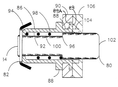
With reference to Figure 9, the lock includes a pin or plunger 80 having a
head or cap 82
at the outer end of a shank 84. The shank is slidingly mounted in a hollow
cylindrical housing 86.
The housing has an inner portion 88 having an innermost end 89 which is bent
upward
from the position illustrated in broken lines in Figure 9 and identified 104.
The end can be bent
by conventional means such as a die, until it is within the annular recess 89A
formed in the
connector. The inner portion of the housing thus is U-shaped in section and
serves to attach the
CA 02357068 2001-09-07
housing to the connector.
The outer end of the housing has a cross-axially extending neck 94.
The shank is stepped outward approximately midway of its ends at 96. Resilient
means in
the form of a coil spring 98 is received in space 100 defined at its ends by
neck 94 and by step
96, and by the inner wall of the housing and the outer wall of the shank. The
spring biases the
plunger to the activated or locked position illustrated in Figure 9. In that
position the inner end
102 of the shank projects through opening 105 of upright 106.
With reference to Figure 10, the plunger is de-activated or unlocked by
grasping head or
cap 82 and pulling it outward to the position illustrated in that Figure. The
inner end of the shank
is then fully withdrawn from the opening in the upright.
In some cases, it may not be desirable that the plunger be unlocked or
deactivated simply
by pulling its head outward. In such cases, the coil spring should be
sufficiently strong to resist
such pulling but not strong enough to resist prying. To facilitate prying, the
head has a somewhat
hollow hemispheric cross-section. The central portion 82A is generally flat
while the peripheral
portion 82B extends radially outward and toward the connector. As illustrated
in Figure 9, there
is no space between the central portion 82A of the head and neck 94 since the
two are in contact
with each ocher. There is however a space between the peripheral portion and
the housing. That
space is sufficient large to receive a prying instrument such as a bottle
opener so that the plunger
can be pried open by this means.
With reference to Figures 11 to 13, the lock is shown fastened to a connector
90 which
2
CA 02357068 2001-09-07
serves to connect upright 106 to beam 110. A rivet 112 is beneath the lock and
extends through
an opening in the connector and terminates at a cylindrical head 114 located
on the inside wall of
the connector as illustrated in Figure 13. The rivet head serves the same
purpose as tab 32
illustrated in Figure 3 of application no. 2,344,727.
Openings 1 OS in upright 106 are in the shape of tear drops and are vertically
spaced along
the outer wall of the upright for receipt of the lock and rivet heads 114.
The lock described in this application has a number of important features:
first the lock
can be retracted by hand and can, as a result, be connected and disconnected
quickly. This is to
be contrasted with locks where special tools or a significant force is
required to open them.
Secondly, the lock described in this application can be constructed of
materials of sufficient
strength that it will not break when struck violently. When the lock is struck
by a fork lift truck,
for example, the lock will not open.
It will be understood of course that modifications can be made in the lock
which is
illustrated and described herein without departing from the scope of the
invention.
