Note: Descriptions are shown in the official language in which they were submitted.
CA 02357480 2005-03-14
CAR WAXii~'G dIACHINE WITH DRIVING H ANDi:E
FIELD OF THE INVENTION
The present invention relates to a waxing machine, and particularly to
a car waxing machine which is a portable electromotive machine, wherein
by pivotal handles at tw-o sides of the car waYin~ machine, the user may
adjust the arms for using the car waxing machine and further
forces can be uniformly applied to the machine.
BACKGROUND OF THE INVENTION
Figs. 1 and 2 and U. S. Patent No. 5830047 discloses a prior art ear
waxing machine. In general, a front side of the wax machine is installed
with a semicircle annular arm 101. The user may hold and press .the arm for
waxing. Since the arm 101 is installed in the front side of the waxing
machine 10, it is hard for the user to apply uniform force thereto. As a
result it is often necessary that the front end of the
sponge disk is in contact with the surface of the car instead of the whole
sponge disk being in contact with the surface. As a result, the waxing work
cannot be executed successfully. Especially wax remains on the
su r face of the car. Thus, the user must wipe a point repeatedly. Therefore,
this prior semicircle arm 101 at the front side of the car waxing machine 10
has the defect of non-uniformly applying force. Similarly. U. S. Patent No.
3849943 illustrates a T shape arm 201, but the same defects occur.
Referring to Fig. 4, to avoid that a non-uniform force! is applied to
the waxing machine, fixing arms 301 at two sides of a waxing machine were
CA 02357480 2005-03-14
developed. _-although this design provides that t-he user may apply farce
uniformly to the waxing machine. in general the wax is coated on the
surface of a car instead of onlybe~~ applied on the.horizontal s~trface.The
w-axin~ surface includes the head, lateral side. etc. Therefore, the operator
must chance pose for waxing. However. above arms at two sides of the arm
301 provide no structure for adjusting orientation. Thus. user can not adjust
the angle as desired. Therefore, this waxing machine 30 having ar_ns ~O1
still has drawbacks.
Moreover, in general. the upper or rear ends of the waxing machines
are extended with power wires for providing power to a motor. The winding
of the power wires will affect the waxing work of the operator. Therefore,
in general. it is desired that the wires are wound around the shoulders of the
operator so as not to affect the holding of the waxing machine. Therefore,
as the user adjusts the angle of the arm freely, the waxing work will not be
interfered by the power wire.
SUMMARY OF THE INVENTION
According to the present invention, there is provided a car waxing
machine comprising a driving motor; two pivotal handles; a casing for
enclosing
the driving motor, the casing having an outer side provided with a power
switch;
and a polishing body driven by the driving motor and located at the bottom of
the
casing, each of the pivotal handles being rod shaped and bent, each of the
pivotal
handles having a rear section provided with a pivotal end and a front end
provided
with an arm; the arms of the two pivotal handles being pivotally connected to
two
opposite sides of a rear end of the casing so that said two arms form a
structure
2
CA 02357480 2005-03-14
which is rotatable by adjusting orientations of the arms, the arms being also
adjustable to horizontally extend from the two opposite sides of the casing.
Preferably, another object of the present invention is to provide a car waxing
machine with a driving handle. wherein the pivotal handle has an arm: a
fixing seat, a shaft, an eccentric shaft, and a movable piece. Thereby, the
movable piece can be removed easily so that the arm can be adjusted.
Furthermore, the movable piece can be closed rapidly.
Preferably, a further object of the present invention is to provide a car
waxing
machine with a driving handle, wherein the arm of the pivotal handle at two
sides of the car waxing machine may be bent like a round arc and have a
holding end which is slightly bent forwards, so that the user may apply
force uniformly to the car waxing machine.
Preferably, a further object of the present invention is to provide a car
waxing
machine with a driving handle, wherein the arm of the pivotal handle at two
sides of the car waxing machine may be bent vertically and have a holding
end which is slightly bent upwards or forwards, so that the user may apply
force uniformly to the car waxing machine. Furthermore, the waxing work
to the car along different direction can be performed easily.
The various objects and advantages of the present invention will be
more readily understood from the following detailed description when read
in conjunction with the appended drawing.
BRIEF DESCRIPTION OF THE DRAWINGS
Fig. 1 is a lateral view of the prior art, wherein the waxingmachine is
3
CA 02357480 2001-09-19
installed in the front end of an arm.
Fig. 2 is an elevatioal view of the prior art, wherein the waxing
machine is installed in the front end of an arm.
Fig. 3 is a perspective view of the prior art, wherein the waxing
machine is installed in the front end of an arm.
Fig. 4 is an elevational view of the prior art, wherein the waxing
machine is installed at two sides of an arm.
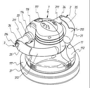
Fig. 5 is a perspective view showing the assembly of the car waxing
machine of the present invention.
Fig. 6 is a partial exploded perspective view of the pivotal handle of
the present invention.
Fig. 7 is an exploded perspective view of the pivotal handle according
to the present invention.
Fig. 8 is an assembled cross sectional view of the pivotal handle
according to the present invention.
Fig. 9 is an operational schematic view of the pivotal handle of the
present invention.
Fig. 10 is a schematic view showing the umbrella shape gear of the
pivotal handle according to the present invention.
Fig. 11 is a schematic view showing the adjustment of angle of the
pivotal handle of the present invention.
Fig. 12 is a schematic view showing the application of the pivotal
handle of the present invention.
Fig. 13 is a cross sectional view of another embodiment of the present
invention wherein the shaft of the pivotal handle is illustrated.
4
CA 02357480 2005-03-14
Fig. 14 is an exploded perspective view of another embodiment of the
protruding seat of the car wa~cina machine according to the present
invention.
Fig. 1~ is a cross sectional view of another embodiment of the pivotal
handle according to the present invention.
Fig. lb is a cross sectional view of another embodiment of the pivotal
handle according to the present invention illustrated one application
thereof.
Fig. 17 is an assembly view of another embodiment of the arm in the
present invention.
Fig. 18 is an assembly view of a further embodiment of the arrn in the
present invention.
DETAILED DESCRIPTION OF THE PREFERRED EMBODIMENTS
Referring to Figs. ~ and 6. the car waxing machine with a driving
handle of the present invention is illustrated. The car waxing machine with
a driving handle includes a car waxing machine I and pivotal handles 2.
The car waxing machine 1 is a portable electromotive waxing machine
which can be used on a car. The outer side thereof is provided with a hollow
cylindrical casing 11 made of plastic or metal material. The upper end of
the casing 11 is providedWith a power switch 111. The lower end thereof is
a U shape round disk I12. The rear side of the casing 11 is provided with a
projecting seat 113. Two sides of the projecting seat 113 are provided with
r a s p a c t i v a p o s t s 1 14 . Each post 114 has a rectangular hole 115
at the center
portion thereof. One lateral wall thereof has a penetrating hole 116.
5
CA 02357480 2005-03-14
Therefore. by above components, the casing 11 of the car waxin~~ machine 1
is formed. A driving motor can be installed therein so as to drive polishing
body 117 at the lower side of the round disk 11? for waging the surface of a
car. The polishing body 117 is a sponUz block. The shape of the casino i 1
can be machined to a desired shape without being confined by above
embodiment.
The pivotal handle ? (referring to Figs. b and 7) is formed by an arm 21,
a fixing seat 22, a shaft 23, an eccentric shaft 24, and a movable piece 25.
The arm ? 1 is a round pivotal end 211. The front section thereof is bent
as cambered holding end 212. The pivotal end 211 is provided with a
protruded triangular teeth shape umbrella shape Gear 213. The center of the
umbrella shape gear 213 is formed with. an axially extending hole 214. Z'he
lateral surface of the pivotal end 211 is provided with a radial penetrating
pivotal hole 215. The piv otal hole 21 ~ is vertical to the axial penetrating
hole 214.
The fixing seat 22 is a round seat. The center of the front surface
thereof is provided with a umbrella shape gear 221 which has triangular
teeth and are concave. The center of the umbrella shape gear 221 is
provided with a stepped hole 222 which penetrates the umbrella shape gear.
The rear side thereof is Provided with a rectangular post 223. One side of
the rectangular post 223 is provided with a radially extending pin hole 224.
The pin hole 224 communicates with the stepped hole 222. A pin 225
passes through the hole.
The shaft 23 is a round cylindrical rod. One end thereof has a threaded
section 231. One lateral surface of the threaded section 231 has a pin hole
6
CA 02357480 2005-03-14
?2. Ths lateral surface of the round e~~lindrical rod is radially installed
with a through hole ? ~ ~. The diameter of the through hole 233 is identical
to that of the pivotal holz 21 ~ of the arm 21.
The eccentric shaft ''~ is a cylindrical shaft 241. The middle section
thereof is provided with an eccentric section 242 having a smaller diameter.
The outer diameter of the eccentric section 2:12 is tangent to the cylindrical
shaft 241 so as to be formed with a shifted round shaft.
The movable piece 25 is installed as a cambered piece and has a U
shape cross section. The two lateral walls at the distal end thereof are
installed with respective pivotal holes 251.
By means of the above components, referring now to Figs.? and 9, the
threaded section 231 of the shaft 23 can be inserted into the stepped hole 222
of
the fixing seat 22. A nut 234 is screwed to the threaded section 231 from the
back
surface of the fixing seat 22 so that the shaft 23 is firmly secured to the
center of
the fixing seat 22. The front end of the shaft 23 passes through the axially
extending hole 214 of the arm 21. Therefore, the umbrella shape gear 213 of
the
arm 21 is engaged to the umbrella shape teeth 221 of the fixing seat 22.
However,
the through hole 233 of the shaft 23 is aligned with the pivotal hole 215 of
the arm
21. Thus, the eccentric shaft 24 extends through the through hole 233 of the
pivotal hole 215. By two ends of the cylindrical shaft 241 of the eccentric
shaft 24,
the pivotal hole 251 of the movable piece 25 is pivotally connected to one
side of
the arm 21. The eccentric section 242 is exactly positioned in the through
hole 233
of the shaft 23 and resists against the inner wall of the through hole 233.
Two
umbrella shape gears 213 and 221 are engaged with
7
CA 02357480 2005-03-14
one another tightl;r. Thzrefore, a pivotal handle ? is formed.
With reference to Fias. 6 and 8, in the present invention, tw-o pivotal
handles ? are selected to pass through the rectangular holes 11 ~ at twe
sides at the rear of the casing 11. Thereby, the pin hole ??=1 of the
fixing seat ?? is aligned to the penetrating hole 116 of the Projecting seat
113 of the casing I1. A pin 22~ passes through the penetrating hole 116 of
the projecting seat113, the pin hole ?24 of the fixing seat 22, and the pin
hole 224 of the shaft 23. Therefore. two pivotal 'handles 2 are firmly
secured to the two sides of. the casino 11. Furthermore, the, cambered arm 21
.
is extended forwards so that the angles of the handles 21 may be adjusted at
two sides of the casing. Therefore, the car waxing machine 1 can be held.
Thereby, the car waxing machine with a driving handle of the present
invention is formed.
About the adjustment of the pivotal handle 2, when the movable piece
25 is separated from the arm 21 (referring to Fig. 9) so as to drive the
eccentric shaft 24 to rotate through an angle and thus the eccentric section
242 does not resist against the hole wall at front side of the through hole
233. Therefore, the arm 21 can be moved by the user directly. By the
umbrella shape gears 213, and 221. as shown in Figs. 10 and 11, an
intermittent buckling is generated so as to adjust the rotating angle of the
arm 21. In detail, the two umbrella shape gears 213, 221 are engaged
slightly. When the arm 21 rotates due to the elasticity of plastics, the
umbrella shape gear 213 may rotate and engaged intermittently. When the
movable piece 25 moves to a predetermined position, see Fig. 8, the
eccentric section 242 of the eccentric shaft 24 resists against the front hole
s
CA 02357480 2005-03-14
wall of the through hole ?33 of the shah ?3, so that thz arm 21 is tightly
engaged with the umbrella shape gears 213. 221 of the fining seat 2? and
thus is fined with a predetermined angl;.. Therefore, the user may adjust the
angle of the pivotal handle 2 formed bv- above components freely.
By aforesaid car waking machine 4vith a driving handle. as shown in
. Figs. 11 and 12, the orientation of the arm 21 is adjustable and are
horizontally arranged at two sides of the car waxing machine 1. Thereby,
the user may hold the arm 21 by two hands and uniformly press the car
waxing machine 1. Thus. the wax can be applied by the polishing body 117 '
at the bottom thereof. Since the forces are applied uniformly, the bottom of
the polishingbody 117 wholly contacts the surface of the car. As a result,
the defect of the prior art that the handle is installed at a front side is
improved and the waxing work is performed effectively. Moreover, by the
design of the pivotal handle 2 of the present invention; when the user waxes
for various part of a car, the user may adjust the angle of the pivotal handle
2 to match different parts of the car or match the habit of the user so as to
wax easily.
The way for securing the shaft 23 of the pivotal handle 2 firmly to the
fixing seat 22 is not confined to the threaded section 23I (referring to Fig.
13). The distal end of the shaft 23 may be provided with a threaded hole 235.
Thereby, the shaft 23 is fixed at the front center of the fixing seat 22. Then
a stud 236 may be used to screw into the threaded hole 235 from the
backside of the fixing seat 22, so that the shaft 23 is steadily combined with
the fixing seat 22.
Furthermore, referring to Fig. 14, for the structure of the protruding
9
CA 02357480 2005-03-14
seat 11 : of the casing 11 of the car waxin; machine 1, the vertical handle
118 at the rear side may be used. The mvo sides of the through hole of the
vertical handle 118 are firmly secured with respective projecting seats 113
for being pivotally- installed with pivotal handle 2. Moreover, as shown in
Fi~~ ~. 14. 1 ~, and 16. in the pivotal handle 2 of the post 114 of the
projecting seat 113, the structure of the rectangular hole 11 ~ and the fixing
seat 2~ can be cancelled. A concave umbrella shape Qear 119 can be
installed at the center of the post 11-1. Further, the distal end of the shaft
23
is formed with a threaded hole 235, and the shaft 23 is placed at the center
'10 of the umbrella shape gear 119 of the post 114. A spring 237 and a stud
236
may be screwed into the threaded hole 23~ of the shaft 23 from the inner
surface of the post 114 so that the shaft 23 is directly combined with the
post 114 of the projecting seat 113. Then the front end of the shaft 23
passes through the penetrating hole 214 of the arm 21. Therefore, the
15 umbrella shape gear 213 of the arm 21 is engaged with the umbrella shape
gear 119 of the post 114.
Moreover, in the present invention, the arm 21 of the pivotal handle 2
is confined to the cambered holding end 212 {referring to Fig. 17). The arm
21' can be bent as a vertical holding end 212'. The fixing seat 22, eccentric
20 shaft 24, movable piece 25, etc. are assembled as above structure. Thereby,
the angle of the holding end 212' of the are 21' is adjustable to horizontally
extend to two sides of the car waxing machine 1 so that users may
uniformly apply force thereto. Furthermore, as shown in Fig. 18, the arm
21' may be bent and have a holding end 212" which is slightly bent upwards.
25 The fixing seat 22, eccentric shaft 24, movable piece 25, etc. are
assembled
CA 02357480 2001-09-19
as above structure. Thereby, the user may execute the action of holding.
pressing downwards, and pushing forwards. Consequently, the car waxing
machine 1 of the present invention can be held conveniently and easily.
The present invention are thus described, it will be obvious that the
same may be varied in many ways, for example, the car waxing machine 1
and the pivotal handle 2 can be modified, but still have the same effect.
Such variations are not to be regarded as a departure from the spirit and
scope of the present invention, and all such modifications as would be
obvious to one skilled in the art are intended to be included within the
scope of the following claims.