Note: Descriptions are shown in the official language in which they were submitted.
CA 02358363 2001-10-05
13435R0CA02U
9-13528-142CA
- 1 -
METHOD OF TEAM MEMBER PROFILE SELECTION WITHIN
A VIRTUAL TEAM ENVIRONMENT
TECHNICAL FIELD
The invention relates in general to work
environments and, in particular, to a virtual team
environment that facilitates collaboration among
geographically-dispersed team members using a distributed
application that provides the virtual team environment.
BACKGROUND OF THE INVENTION
The knowledge economy is fundamentally affecting
the modern work environment. As
demand for knowledge
workers increases, new work paradigms are being developed
in which specialized teams are assembled for specific
projects.
Those specialized teams may need to work
together for a matter of days, weeks or months to
accomplish a given project. With more regularity, the team
is disbanded after the project is completed and team
members move on to other projects, often working with a
partly or completely different group of people. In
addition, people who need to work together are increasingly
geographically dispersed due to corporate partnering,
acquisitions, globalization, and related factors.
While
there is motivation for people to work together more
closely and more effectively due to competitive pressures,
the increasing geographical dispersion of talent in the
workforce creates a dilemma which is not easily resolved.
It is generally accepted that people work together
best when they are physically collocated.
Physical
collocation facilitates communications, and therefore
collaboration, that is responsive, efficient and
CA 02358363 2001-10-05
13435R0CA02U
9-13528-142CA
- 2 -
spontaneous.
Physical collocation in today's business
world is not, however, generally practical even when
workers are employed by the same company.
The stresses
associated with travel and commuting often prevent or
impair the efficiency of bringing co-workers into physical
collocation in order to facilitate job function.
Modern telecommunications services facilitate
collaboration among co-workers.
Services such as the
Public Switched Telephone Network (PSTN), the Internet, and
related services such as facsimile, electronic mail,
instant messaging, one-way and two-way paging services all
contribute to enable and facilitate collaboration. As
currently available, however, such services are not
optimized to facilitate collaboration between team members.
For example, even though modern facilities, such as
described in co-applicants' United States Patent
No. 6,097,804 which issued August 1, 2000 and is entitled
METHOD AND SYSTEM FOR COMPLETING A VOICE CONNECTION BETWEEN
FIRST AND SECOND VOICE TERMINALS IN A SWITCHED TELEPHONE
NETWORK, facilitate call setup and control by permitting
calls to be initiated from a worldwide web interface or the
like, problems are still inherent. It is still impossible
to determine the availability of a called party before a
call is placed. Even when a call attempt is unsuccessful,
the caller is generally not provided with any feedback to
indicate why the call attempt failed.
For example, the
called party may be on another call, or may be away from
their desk or office. It
is estimated that at least as
many as 84% (6 out of 7) of business calls fail to connect
directly to the called party.
Electronic mail provides a convenient and
inexpensive mode of communication. Electronic mail tends,
CA 02358363 2001-10-05
13435R0CA02U
9-13528-142CA
- 3 -
however, to be a relatively slow method of communication.
Recently, instant messaging has become increasingly
accepted and services such as Yahoo Messenger are
experiencing explosive growth with millions of subscribers.
Instant messaging services provide a means of exchanging
messages between two or more participants in a messaging
session in near real time. With Yahoo Messenger a user
can define a group of "friends" by selecting other
registered users who accept being listed among the user's
group of friends. After the group of friends is
established, the user who established the group receives
dynamic status information respecting the presence of the
group of friends at their computer workstation.
Consequently, the instant messaging user has a prior
knowledge of whether other members in the group of friends
are logged on to the Yahoo Messenger and, if so, whether
they have used their workstation within the past few
minutes.
Yahoo Messenger also permits Net2Phone
conversations to be initiated between a user and another
party using a graphical user interface that provides a dial
pad and an address book to initiate calls that are set up
as a first leg through the Internet and a second leg
through the PSTN, in accordance with a service provided by
Net2Phone . However, no availability information is
provided respecting the called party or the disposition of
their telephone. Therefore, it is impossible for a Yahoo
Messenger subscriber to know the status of a "friend's"
telephone before a call is placed. Furthermore, each user
of the Yahoo Messenger service must define their own group
of friends. There is no central facility for defining a
group or a team, and there is no method of controlling
congruence between two groups defined by individual users.
-----
CA 02358363 2001-10-05
13435R0CA02U
9-13528-142CA
- 4 -
Consequently, although Yahoo Messenger facilitates message
exchange, it is not adapted to provide a cohesive
collaboration environment for geographically-dispersed
teams working at a professional level.
Other applications also exist to facilitate
collaboration among geographically-dispersed parties. For
example, Microsoft Corporation provides NetMeeting which
is adapted to enable collaboration between two or more
people using text chat, streaming video, and/or voice over
Internet Protocol (VoIP) conversation. NetMeeting also
supports document and application sharing, as well as an
exchange of cursor control.
While NetMeeting is a
powerful collaboration tool, it only functions well in
two-way communications sessions, and fails to provide
functionality for defining or tracking of a team.
Furthermore, knowledge of respective Internet Protocol (IP)
addresses of each participant is required in order to
establish a direct inter-party session. Two-party and
multi-partly sessions can be established using a Microsoft
NetMeeting server without knowledge of respective IP
addresses, however, session efficiency and performance are
compromised.
As a further example, Teamcast.com provides a
collaboration tool that permits the definition of a team
and enables project and event tracking. The Teamcast.com
tool also enables communications by electronic mail and
instant messaging. The collaborative tool fails, however,
to instantiate a virtual team environment that provides
knowledge of the availability of other team members to
facilitate communications attempts. It also fails to
facilitate voice or multimedia communications among team
members.
CA 02358363 2001-10-05
13435R0CA02U 9-13528-142CA
- 5 -
There therefore exists a need for a tool that
facilitates collaboration among geographically-dispersed
members of a team by creating a virtual team environment
that provides dynamic preference and presence information
to permit communications sessions among team members to be
transparently established.
SUMMARY OF THE INVENTION
An object of the present invention is to provide a
method for enabling a team member to dynamically define
communications preferences concerning participation in each
of a plurality of different types of communications.
Accordingly, an aspect of the present invention
provides a team member profile maintained by a persistent
collaboration services suite for facilitating collaboration
between members of a team, the team member profile
comprising communications information defining preferences
of a respective team member for participating in each one
of a plurality of different types of communications.
In embodiments of the present invention, the types
of communications include: 1-way messaging; 2-way
messaging; voice; and multi-media. 1-way messaging may
include one or more of paging, and e-mail. 2-way messaging
may include instant messaging (IM). Multi-media
communications may include one or more of: document
sharing; application sharing; 1-way video conferencing; and
2-way video conferencing.
Preferably, the communications information
includes, for each one of the plurality of different types
of communications, a selected one of: an indication that
the respective team member prefers not to participate in
CA 02358363 2001-10-05
13435R0CA02U
9-13528-142CA
- 6 -
the respective type of communications; and communications
preference information identifying a
preferred
communications device selected by the respective team
member for participating in the respective type of
communications. The communications preference information
may include at least an address of the preferred
communications device. The address may include any one or
more of: a Public Switched Telephone Network (PSTN)
destination number (DN); a Private Branch Exchange (PBX)
extension number; an internet protocol (IP) address; and an
e-mail address.
In embodiments of the invention, a plurality of
team member profiles are instantiated in respect of the
team member. Each team member profile may include
respective different communications information defining
preferences of the respective team member for participating
in each one of the plurality of different types of
communications. Each team member profile may be associated
with a respective one of a plurality of different roles of
the team member. Each one of the plurality of different
roles may be defined by the respective team member, and may
include a Working role of the team member. Each team member
profile may be further associated with a respective one of
a plurality of different environments of the team member.
As with roles, each one of the different environments may
be defined by the respective team member, and may include
an office environment of the team member.
Preferably, each one of the plurality of team
member profiles is defined by the respective team member.
Preferably, one of the plurality of team member
profiles is selected by the team member as a current
profile.
CA 02358363 2001-10-05
13435R0CA02U
9-13528-142CA
- 7 -
Another aspect of the present invention provides
method for enabling a team member to select a respective
team member profile maintained by a persistent
collaboration services suite for facilitating collaboration
between members of a team. The team member is enabled to
interact with the persistent collaboration services suite
to select communications information defining preferences
of the team member for participating in each one of a
plurality of different types of communications.
In some embodiments of the invention, the team
member may be enabled to interact with the persistent
collaboration services suite by providing an Interactive
Voice Response (IVR) interface to the persistent
collaboration services suite. The team member can then be
enabled to access the IVR using a voice communications
device. In such cases, an announcement can be played
including information of one or more options concerning the
communications information. One or more dialed digits
dialed by the team member, in response to the announcement,
can them be received, and the communications information
selected using the received dialed digits.
The information of one or more options may include
information identifying each one of a plurality of team
member profiles, each team member profile including
respective different communications information. In
such
cases, the dialed digits dialed by the team member may
provide an indication of a preferred one of the plurality
of the team member profiles.
Thus the communications
preference information can be selected by using the dialed
digits dialed by the team member to select one of the
plurality of team member profiles as a current profile.
CA 02358363 2001-10-05
13435R0CA02U
9-13528-142CA
- 8 -
In some embodiments of the invention the team
member is enabled to interact with the persistent
collaboration services suite by providing a graphical user
interface (GUI) adapted to interact with the persistent
collaboration services suite. The team member may then
access the graphical interface using a GUI-enabled
communications device. The GUI may be instantiated in the
GUI-enabled communications device and adapted to interact
with the collaboration services suite through a network.
Alternatively, the GUI may be instantiated by a web page
associated with the collaboration services suite and
accessible by the GUI-enabled communications device through
an IP network. Exemplary GUI-enabled communications devices
usable with the invention include any one of: a PC; a
wireless PDA; and a Wireless Application Protocol (WAP)
enabled communications device.
The team member may be enabled to interact with the
persistent collaboration services suite by using the GUI to
display information of one or more options concerning the
communications information. An input from the team member
indicative of a team member selection may be received, and
the communications information selected using the input
from the team member. The information of one or more
options may include information identifying each one of a
plurality of team member profiles, each team member profile
including respective different communications information.
In such cases, selection of the communications information
may include using the input from the team member to select
one of the plurality of the team member profiles as a
current profile.
In some embodiments, the information of one or more
options may include information identifying a preference of
CA 02358363 2001-10-05
13435R0CA02U
9-13528-142CA
- 9 -
the team member for participating in each one of the
plurality of different types if communications. In such
cases, selection of the communications information may
include, in respect of each one of the plurality of
different types of communications, using the input from the
team member to select one of: an indication that the team
member is prefers not to participate in the respective type
of communications; and information identifying a preferred
communications device selected by the team member for
participating in the respective type of communications. The
information identifying a preferred communications device
may include at least an address of the preferred
communications device. The address may include any one or
more of: a Public Switched Telephone Network (PSTN)
destination number (DN); a Private Branch Exchange (PBX)
extension number; an Internet protocol (IP) address; and an
e-mail address.
The invention therefore provides a user-friendly
mechanism that enables users of the collaboration services
suite to define and select communications preferences
concerning participation in each of a plurality of
different types of communications. The collaboration
services suite automatically uses the communications
preferences to control the setup of communications sessions
in which the user is a participant.
BRIEF DESCRIPTION OF THE DRAWINGS
Further features and advantages of the present
invention will become apparent from the following detailed
description, taken in combination with the appended
drawings, in which:
CA 02358363 2001-10-05
13435R0CA02U
9-13528-142CA
- 10 -
FIG. 1 is a block diagram schematically
illustrating exemplary interactions between a collaboration
services suite and members of a team in accordance with an
embodiment of the present invention;
FIG. 2 is a block diagram schematically
illustrating principle elements in a system for
implementing the collaboration services suite of FIG. 1;
FIG. 3 is a block diagram schematically
illustrating exemplary relationships between communications
devices encompassed by each VTE client and communications
network elements involved in enabling the functionality of
the collaboration services suite of FIG. 1, in accordance
with a first embodiment of the invention;
FIG. 4 is a block diagram schematically
illustrating exemplary relationships between communications
devices encompassed by each VTE client and communications
network elements involved in enabling the functionality of
the collaboration services suite of FIG. 1, in accordance
with a second embodiment of the invention;
FIG. 5 is a block diagram schematically
illustrating exemplary functionality of the VTE server of
FIG. 2 in accordance with an embodiment of the present
invention;
FIG. 6 is a block diagram schematically
illustrating principal functional elements of a VTE client
application in accordance with an embodiment of the present
invention;
FIG. 7 is a message flow diagram illustrating
exemplary messages exchanged between the collaboration
services suite and the VTE client application;
CA 02358363 2001-10-05
13435R0CA02U
9-13528-142CA
- 11 -
FIG. 8 is a message flow diagram illustrating
exemplary messages exchanged between the VTE client
application and elements of the collaboration services
suite during a team member log-in procedure;
FIG. 9 is a message flow diagram illustrating
exemplary messages exchanged between the VT client
application and elements of the collaboration services
suite during a team member log-out procedure;
FIG. 10 is a block diagram schematically
illustrating exemplary frames of the virtual team space
display instantiated by the VTE client application, in
accordance with an embodiment of the present invention;
FIG. 11 is a block diagram schematically
illustrating exemplary elements of the menu frame of the
team space display of FIG. 10;
FIG. 12 is a message flow diagram schematically
illustrating exemplary messages exchanged between the VTE
client application and elements of the collaboration
services suite during creation and/or editing of a personal
profile;
FIG. 13 is a message flow diagram schematically
illustrating exemplary messages exchanged between the VTE
client application and elements of the collaboration
services suite during team member selection of an active
profile;
FIG. 14 is a message flow diagram schematically
illustrating principle messages exchanged among three VTE
clients and elements of the collaboration services suite
during creation of a team;
CA 02358363 2001-10-05
13435R0CA02U
9-13528-142CA
- 12 -
FIG. 15 is a schematic block diagram illustrating
exemplary contents and functionality associated with the
current availability frame of the team space display of
FIG. 10;
FIG. 16 is a block diagram schematically
illustrating exemplary functionality of the VTE client
application accessible using team member preference and
presence information displayed in the team view of the team
space display of FIG. 10;
FIG. 17 is a message flow diagram illustrating
exemplary functionality and message flows between the VTE
client application and elements of the collaboration
services suite in respect of detection and propagation of
team member presence information to each of the members of
a team;
FIG. 18 is a block diagram schematically
illustrating exemplary elements of the team bulletins frame
of the team space display of FIG. 10;
FIG. 19 is a block diagram schematically
illustrating the active communications frame of the team
space display of FIG. 10;
FIG. 20 is a message flow diagram illustrating
exemplary messages exchanged between VTE client
applications and the VTE server during a public
communications session;
FIG. 21 is a block diagram schematically
illustrating exemplary functionality associated with an
Instant Messaging Session Object instantiated by a VTE
Client application in respect of an Instant Messaging
communications session;
CA 02358363 2001-10-05
13435R0CA02U
9-13528-142CA
- 13 -
FIG. 22 is a block diagram schematically
illustrating exemplary functionality associated with a
Voice Session Object instantiated by a VTE Client
application in respect of a voice communications session;
FIG. 23 is a block diagram schematically
illustrating exemplary functionality associated with a
Multi-media Session Object instantiated by a VTE Client
application in respect of a multi-media communications
session;
FIG. 24 is a block diagram schematically
illustrating exemplary functionality associated with an
invitation object instantiated by a VTE client application
for inviting a new participant to join an active
communications session;
FIG. 25 is a block diagram schematically
illustrating exemplary functionality of a VTE client
application associated with an Invitation message received
from another team member via the collaboration services
suite;
FIG. 26 is a message flow diagram illustrating the
setup of a two-way voice communications session using the
VTE Client application and the collaboration services suite
in accordance with the invention;
FIG. 27 is a schematic diagram illustrating the
closing of the two-way voice communications session setup
shown in FIG. 26;
FIGs. 28, 28a and 28b are message flow diagrams
showing the voice communications session setup as shown in
FIG. 26;
CA 02358363 2001-10-05
13435R0CA02U
9-13528-142CA
- 14 -
FIGs. 29 and 29a show the closing of the three-way
voice communications session setup as shown in
FIGs. 28-28b;
FIG. 30 is a message flow diagram showing the setup
of a two-way voice communications session in an enterprise
network;
FIG. 31 is a message flow diagram showing the
addition of a third party to a two-way voice communications
session setup in an enterprise network as shown in FIG. 30;
FIGs. 32, 32a and 32b are message flow diagrams
illustrating the conversion of a three-way instant
messaging session to a three-way voice communications
session using the VTE client application and the
collaboration services suite in accordance with an
embodiment of the invention;
FIG. 33 shows the setup of a two-way multi-media
session;
FIG. 34 shows the additional of a third party to
the multi-media session setup as shown in FIG. 33;
FIG. 35 shows the addition of a third party to a
multi-media session setup as shown in FIG. 33 when the
third party defers acceptance; and
FIGs. 36 and 36a show the addition of a third party
to a multi-medial session setup when the invited party is
not logged into the collaboration services suite as a
virtual team environment client.
It will be noted that throughout the appended
drawings, like features are identified by like reference
numerals.
CA 02358363 2001-10-05
13435R0CA02U
9-13528-142CA
- 15 -
DETAILED DESCRIPTION OF THE PREFERRED EMBODIMENT
The present invention provides a collaboration
services suite 2 which is designed to instantiate a virtual
team environment (VTE) 3 for integrating, in a synergistic
manner, a plurality of traditional, emerging, and new
communications-related capabilities to
facilitate
collaboration among geographically dispersed members of a
team. As used in this document, the word "team" means any
group of interested parties that have a desire to
collaborate for business, academic, political or social
reasons.
Although the description that follows refers
specifically to "work teams", it should be understood that
the virtual team environment may be used for many other
purposes.
For example, the methods and apparatus in
accordance with the invention may be used by families,
groups of friends, academic institutions, political
organizations or any other closely or loosely associated
group interested in seamless communications services. The
methods and apparatus in accordance with the invention also
have a plurality of business applications too large to
exhaustively enumerate. For example, the invention may be
used for customer relationship management, institutional
information exchange, distributed health
care
administration, hot-line and help-line services, etc. In
some applications, preference and presence information,
described below in some detail, may only be available to
selected parties, and not to all parties as described in
the detailed description of the preferred embodiments that
follows.
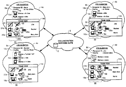
FIG. 1 is a block diagram schematically
illustrating exemplary interactions between
the
collaboration services suite 2 and each of the members of a
team. In
the embodiment illustrated in FIG. 1, the team
CA 02358363 2001-10-05
13435ROCA02U
9-13528-142CA
- 16 -
comprises four team members, each of whom is represented by
a respective VTE client 4. As
shown in FIG. 1, the
collaboration services suite 2 includes a database 6 in
which information concerning each team member is stored.
This information includes a respective personal
identifier 8 of each team member, a respective personal
profile 10 relating to a role and/or environment of the
team member, and communications information 12 indicative
of the availability of the respective team member for
participating in various types of communications. As will
be described in greater detail below, information
concerning a team member's respective personal
identifier 8, and profile 10, as well as communications
preferences (e.g. communications information 12 defining
preferred communications devices and addresses) are
provided by each team member, and stored by the
collaboration services suite 2 in
the database 6.
Information concerning an availability of each team member
to participate in various types of communications can be
provided by the respective team member and/or detected
automatically by the collaboration services suite 2. The
information concerning each team member is compiled within
the collaboration services suite 2 and then supplied to
each VTE client 4, in the form of team member presence and
preference information, in order to provide each team
member with a consistent team view 14 that is
representative of the status of each of the members of the
team.
Thus, for example, Hank (represented by VTE
client (A) 4a)
has specified a personal profile 10a
indicating that he is currently working in his office. As
part of this personal profile, Hank has provided
communications information 12a identifying his office
personal computer (PC) 16 (which includes two-way video
CA 02358363 2001-10-05
13435R0CA02U
9-13528-142CA
- 17 -
conferencing capability) and his office telephone 18 as
communications devices through which he prefers to receive
communications. By interaction with the VTE client (A) 4a
and the PSTN, the collaboration services suite 2 has
detected that Hank's PC 16 is currently in use, and his
office telephone 18 is idle.
Similarly, Mary Ann
(represented by VTE client (B) 4b) has selected a personal
profile 10b indicating that she is working at her home.
She has also specified communications information 12b
defining a pair of communications devices (in this case her
home PC 20 and wireline telephone 22) through which she
prefers to receive communications. By means of interaction
with the VTE client (B) 4b, and the PSTN, the collaboration
services suite 2 has detected that Mary Ann's home PC 20 is
idle, and that her wireline telephone 22 is currently in
use.
Rachel (represented by VTE client (C) 4c) has
specified a personal profile 10c indicating that she is
mobile.
She has also specified communications
information 12c identifying three communications devices
(in this case a wireless PDA 24, a wireless telephone 26
and a 2-way pager device 28) through which she prefers to
receive communications. By means of interaction with the
VTE client (C) 4c and the PSTN, the collaboration services
suite 2 has detected that Rachel's wireless PDA 24 is in
use, her wireless telephone 26 is currently turned off (or
is otherwise inaccessible), and that her 2-way pager 28 is
currently idle.
Finally, Jim (represented by VTE
client (D) 4d) has selected a profile indicating that he is
unavailable. As part of this profile Jim has specified no
communications devices through which he prefers to receive
communications.
The above-described communication preferences and
status information, concerning each of the members of the
CA 02358363 2001-10-05
13435R0CA02U
9-13528-142CA
- 18 -
team, is combined by the collaboration services suite 2 and
distributed to each of the team members for display using a
team view 14 providing a consistent view of the team. In
each case, the team view 14 includes the personal
identifier 8 of each of the other members of the team,
along with respective preference and presence
information 30 (in the illustrated embodiment represented
by icons) indicative of the capability of each team member
to participate in various types of communications. Thus,
for example, the preference and presence information of
Hank (VTE client (A) 4a) is indicated by respective device
icons 16a and 18a representative of the office PC 16 and
wireline telephone 18 identified in Hank's "in the office"
profile 10a. The In-Use status of Hank's office PC 16 is
indicated by a presence icon 32 partially superimposed over
the office PC icon 16a, while the Idle status of Hank's
office telephone 18 is indicated by the lack of any other
presence icon elements associated with the wireline
telephone icon 18a.
The status and availability
information for Rachel comprises icons 24a, 26a, 28a,
respectively representative of each of the wireless PDA 24,
wireless telephone 26 and the 2-way pager device 28 that
Rachel has identified in her profile 10c.
The In-Use
status of Rachel's PDA 24 is indicated by a presence
icon 32 (in this case a graphical representation of a human
head) partially superimposed over the PDA icon 24a. The
Inaccessible status of her wireless telephone 26 is
indicated by an "inaccesible" icon 35 (in this case a
circle) superimposed over the wireless telephone icon 26a.
The Idle status of her 2-way pager 28 is indicated by the
lack of any other icon elements associated with the two-way
pager icon 28a.
The preference and presence information
for Mary Ann includes a pair of device icons 20a and 22a
CA 02358363 2001-10-05
13435R0CA02U
9-13528-142CA
- 19 -
respectively representative of the home PC 20 and the
wireline telephone 22 that Mary Ann has identified in her
"at home" profile 10b. The Idle status of Mary Ann's PC 20
is represented by the absence of any other presence or
status icon elements associated with the PC icon
element 20a, whereas the In-Use status of her wireline
telephone 22 is indicated by a presence icon element 32
partially superimposed over the wireline telephone device
icon 22a. Finally, the preference and presence information
of Jim is indicated by generic device icons 36 and 38,
respectively representative of the text and voice
communications types, each of which includes a not
available icon 34 indicating that Jim is not available to
receive either of the respective types of communications.
In preferred embodiments of the present invention,
the collaboration services suite 2 is "persistent" in that
it remains active independently of the Log-In status of any
of the members of the team.
Thus, for example, Jim's
preference and presence information 30 is maintained by the
collaboration services suite 2 and displayed consistently
in the team views 14 of each of Mary Ann, Rachel and Hank,
independently of whether or not Jim is logged into the
collaboration services suite 2.
Similarly, the "in the
office" profile 10 defined by Hank (including the
communications information and the operational status of
each of the identified communications devices) will be
maintained by the collaboration services
suite 2
independently of whether or not Hank is logged into the
collaboration services suite 2.
Accordingly, the other
members of the team (e.g. each of Jim, Rachel and Mary Ann)
will be able to view the preference and presence
information for Hank, and may use this information to
CA 02358363 2001-10-05
13435R0CA02U
9-13528-142CA
- 20 -
establish communications with Hank, even if Hank is not
currently logged into the collaboration services suite 2.
FIG. 2 is a block diagram
schematically
illustrating principle elements in a system for
implementing the collaboration services suite 2. In
general, the collaboration services suite 2 is instantiated
by a collaboration services suite comprising a VTE
server 40, a Presence Server 42, and the database 6. Each
VTE client 4 encompasses one or more communications
devices, such as wireline and wireless telephones connected
to the public switched telephone network (PSTN), and
packet-based communications devices such as personal
computers (PCs), personal digital assistants (PDAs), and
other one and two-way messaging devices. Many packet-based
communications devices incorporate a graphical user
interface capable of supporting a VTE client application 44
(see Fig. 6) providing a team member with the team view 14
and functionality for interacting with the collaboration
services suite 2 to define and edit their respective
personal profiles 10, and for initiating and controlling
communications with other persons. In general, interaction
between the collaboration services suite 2 and the
communications devices associated with each team member
(i.e. encompassed by each VTE client 4) is controlled by
the VTE server 40.
Accordingly, the VTE server 40
incorporates functionality related to the negotiation of
team member log-in to the collaboration services suite 2,
the forwarding of team member preference and presence
information 30 to each VTE client 4, and the forwarding of
status updates concerning active communications sessions to
each VTE client 4. The VTE server 40 also
provides
functionality related to the initiation and control of
CA 02358363 2009-11-20
13435R0CA02
- 21 -
communications involving one or more team members, as will
be described in greater detail below.
The Presence Server 42 incorporates functionality
adapted to detect the current operational status of each of
the communications devices identified in the current
profile 10, and store the detection result within the
database 6 as communications information for each
respective VTE client 4. For this purpose, the Presence
Server 42 is preferably adapted to detect team member
presence information using the techniques described in
Applicant's co-pending United States Patent Applications
Nos. 09/460,780; 09/461,119; and 09/461,492 (all filed
December 14, 1999). Thus the Presence Server 42 interacts
with packet-based communications devices (e.g. PCs, web-
enabled communications devices, and WAP-enabled
communications devices) through a packet network 46 to
receive StatusUpdate messages, and determine associated
presence information based on the reception and contents of
such StatusUpdate messages, as will be described in greater
detail below. In addition, the Presence Server 42 includes
functionality adapted to formulate at least the functional
contents of a common channel signalling (CCS) Query
messages for determining the current status of wireline and
wireless telephones through the PSTN 48, again, as will be
described in greater detail below.
Additionally, the Presence Server 42 maintains a
status table 43 for controlling the detection and
propagation of team member status and availability
information. In general, the status table 43 contains, for
each member of the team, a logged-in frame 43a; a devices
frame 43b, and a watcher's frame 43c. The logged-in
ommol
CA 02358363 2001-10-05
13435R0CA02U
9-13528-142CA
- 22 -
frame 43a stores a flag (e.g. a binary "0" or "1")
indicating whether or not the respective team member is
currently logged-in to the collaboration services suite 2.
The devices frame 43b contains device identifiers and
associated address information (e.g. PSTN destination
number, IP address, e-mail address) for each communications
device identified by the respective team member in their
current personal profile. Finally, the watcher's frame 43c
contains the personal identifiers of each of the other
members of the team who are currently also logged-in to the
collaboration services suite 2, and who should therefore be
receiving preference and presence information respecting
the team member.
In order to facilitate interaction between each of
the VTE server 40 and the Presence Server 42, and the
PSTN 48, a call server 50 may be provided. Similarly, a
connection manager 52 can be provided to facilitate
protocol-independent messaging between the VTE server 40
and packet-based communications devices associated with
each of the VTE clients 4. In the illustrated embodiment,
interaction between each VTE client 4 and the collaboration
services suite 2 is implemented by packet-based messaging
between respective communications devices associated with
each VTE client 4 and the VTE server 40, via the packet
network 46 and the connection manager 52. However, it will
be appreciated that, in some cases, it will be advantageous
to enable direct messaging between the presence server 42
and communications devices associated with each VTE
client 4, without the involvement of the VTE server 40, as
shown in FIG. 2. It will also be appreciated that, in some
embodiments, a connection manager 52 may not be required,
or that its functionality may be incorporated into the VTE
server 40 and/or the presence server 42.
CA 02358363 2001-10-05
13435R0CA02U
9-13528-142CA
- 23 -
The VTE server 40, Presence
Server 42, and
database 6 may be co-resident within a single server
machine, or alternatively may be deployed across two or
more machines suitably interconnected (e.g. through the
packet network 46, or through high-speed ethernet links) in
order to facilitate messaging and data exchange.
Similarly, each of the call server 50 and the connection
manager 52 may be co-resident with the VTE server 40, or
may be remotely located and accessible by the VTE server 40
(and the Presence Server 42) via suitable data links.
As described above with respect to FIGs. 1 and 2,
each VTE client 4 encompasses communications devices usable
by a respective team member for engaging in communications
with other persons (who may or may not be members of the
same team). In
general, any of a variety of different
types of communications devices may be utilized in
conjunction with the present invention, including PCs,
PDAs, wireless and wireline telephones, and wireless one
and two-way messaging devices.
Similarly, the
collaboration services suite 2 may be utilized to
facilitate any of a variety of different types of
communications, including two-way instant messaging,
e-mail, multi-media (including video conferencing) and
voice communications. In the present network space,
communications between any two parties may, depending on
the type of communications devices involved, be facilitated
through the legacy PSTN 48 or a packet network 46 (e.g. one
or more federated ethernet, ATM, or IP networks). Thus, it
is possible to categorize the various communications
devices in accordance with whether they are designed to
effect communications through the PSTN 48 or a packet
network 46. Within each of these categories, it is largely
irrelevant (for the purposes of
establishing
CA 02358363 2001-10-05
13435R0CA02U
9-13528-142CA
- 24 -
communications) whether a particular communications device
relies on a wireline or a wireless connection to access the
network, as this does not generally have a significant
effect on the messaging required to complete a call
connection to the involved communications device. This
separation of communications devices into packet-based and
PSTN based communications devices is illustrated in FIGs. 3
and 4.
FIG. 3 is a block diagram
schematically
illustrating relationships between packet-based and PSTN
based communications devices encompassed by each of VTE
clients (A),
(B) and (C) 4a, 4b, 4c (see FIG. 1) and
elements of the packet network 46, PSTN 48 and CCS
network 53 involved in enabling the functionality of the
collaboration services suite 2 in accordance with the
present invention. In the scenario illustrated in FIG. 3,
each of the PSTN-based devices 54 (whether wireline or
wireless telephone sets) are hosted by a respective service
switch point (SSP) 56 of the PSTN.
Conversely, the
respective packet-based communications devices 58 are
connected to the packet network 46 either directly or via
an access server (not shown) provided by a network access
provider. In
order to enable the collaboration services
suite 2 to detect an operational status of the PSTN-based
communications devices 54, and to initiate and control
communications involving the PSTN-based communications
devices 54, a virtual switching point (VSP) 60 of the CCS
network 53 is adapted to interact with the VTE server 40
via, for example, a suitable connection to the packet
network 46. As is known in the art, the VSP 60 is adapted
to interact with one or more Integrated Services Digital
Network User Port (ISUP) trunk groups referred to a
enhanced ISUP (E-ISUP) trunks 62 to control the set up of
CA 02358363 2001-10-05
13435R0CA02U
9-13528-142CA
- 25 -
call connections through the PSTN 48. This functionality
is utilized by the collaboration services suite 2 to enable
the establishment of multi-way communications sessions
through a conventional conference bridge 64, as will be
described in greater detail below.
FIG. 4 is similar to FIG. 3 in that it illustrates
relationships between packet-based and PSTN-based
communications devices 58,54 and respective elements of the
packet network 46, CCS network 53 and PSTN 48 involved in
the set up and control of communications involving one or
more team members.
The scenario of FIG. 4 differs from
that of FIG. 3 in that the PSTN-based communications
devices of VTE clients (B) and (C) 4b, 4c are connected to
the PSTN 48 via a private branch exchange (PBX) 66 which
provides various communications services within an
enterprise network 68, and is logically connected to the
presence server 42 (e.g. via the packet network 46) through
a data link 67.
FIG. 5 is a block diagram
schematically
illustrating exemplary functionality of the VTE server 40
in accordance with an embodiment of the present invention.
In the illustrated embodiment, the VTE server 40 comprises:
a profile manager 70 providing functionality related to the
creation and editing of personal profiles 10; a presence
manager 72 enabling interaction between the VTE server 40
and the Presence Server 42 to maintain up-to-date presence
information concerning each team member; a database
manager 74 enabling interaction between the VTE server 40
and one or more databases 6 of the collaboration services
suite 2; and a
collaboration manager 76 providing
functionality relating to the initiation and control of
communications involving one or more team members. In
CA 02358363 2001-10-05
13435R0CA021J
9-13528-142CA
- 26 -
addition, the VTE server 40 includes member registration
services 78, providing functionality related to member
authentication and authorization during user log-in; and
utilities services 80 providing functionality related to
team administration, including tracking and resolution of
alarms, accumulation of various statistics and logs,
encryption services and authentication routines. Finally,
the VTE server 40 includes a conference manager 82 which
interacts with the collaboration manager 76 to provide
signaling and messaging functionality required for the
initiation and control of communications; an instant
messaging server 84 which interacts with the collaboration
manager 76 to provide specialized services with respect to
the management and control of instant messaging sessions;
and a connection manager interface 86 which facilitates
interaction between the VTE server 40 and the connection
manager 52, and so facilitates messaging between each VTE
client 4 and the VTE server 40.
Thus constructed, the VTE server 40 embodies a
modular architecture in which collaboration services, such
as those associated with the set up and control of
multi-party communications sessions, can be developed and
implemented independently of the messaging protocols used
for interaction between the VTE server 40, the VTE
clients 4, the database 6, the Presence Server 42, or any
of the communications devices 54, 58 and networks with
which the collaboration services suite must operate in
order to instantiate the collaboration services suite 2.
For example, in the embodiment illustrated in FIG. 5, the
database manager 74 includes one or more structured query
language (SQL) and lightweight directory access protocol
(LDAP) interfaces 88, 90 respectively enabling interaction
between the VTE server 40 and one or more LDAP and SQL
CA 02358363 2001-10-05
13435R0CA02U 9-13528-142CA
- 27 -
databases. Other database types may be accessed by the VTE
server 40 through the database manager 74 by providing a
suitable interface (e.g. a java database connectivity
(JDBC) interface) within the database manager 74.
Similarly, the presence manager 72 instantiates a Presence
Server interface 92 facilitating interaction between the
VTE server 40 and the Presence Server 42 using a suitable
messaging protocol, such as, for example, session
initiation protocol (SIP).
During initialization of communications involving
one or more team members, the collaboration manager 76 may
conveniently operate to generate a session record including
session specific information such as a session ID, a start
time, information identifying session participants, a
session type, and other information useful for
administration and archiving of the communications session.
Once the communications record has been generated, it may
conveniently be passed to the conference manager 82, which
interacts with elements of the packet network 48 and/or the
PSTN 48 to set up the requested communications session
between the involved parties. Thereafter, the conference
manager 82 may be used to update the session record as new
session information is accumulated, and the status of the
communications session changes. In order to enable
interaction between the conference manager 82, the PSTN 48,
and the packet network 46, the conference manager 82 may
instantiate one or more conference interfaces 94 which may,
for example, enable interaction with both the packet
network 46 and the call server 50 using session initiation
protocol.
The connection manager interface 86 provides
functionality enabling interaction between the VTE
CA 02358363 2001-10-05
13435R0CA02U
9-13528-142CA
- 28 -
server 40 and the connection manager in order to facilitate
protocol independent messaging between the VTE Server 40
and each VTE client 4.
The connection manager 52 may
instantiate one or more of an HTTP proxy interface 96, a
transport control protocol/internet protocol (TCP/IP)
interface 98, and user datagram protocol/internet protocol
(UDP/IP)
interface 100 for interacting with client
applications instantiated on suitable packet-based
communications devices 58 (e.g. PCs, PDAs, and WAP-enabled
communications devices). Additionally, the connection
manager 52 may implement an Interactive Voice Response
(IVR) interface 102 enabling a team member to interact with
the VTE server 40 by means of a voice communications device
connected, for example, to the PSTN 48. In
those
embodiments in which direct messaging between the presence
server 42 and VTE clients 4 is desired, a Presence server
interface 103 may be instantiated to facilitate messaging
between the connection manager 52 and the presence server
42.
In order to facilitate web-based access to the
functionality of the VTE server 40, the utility services 80
may include a web server 104 and/or an extensible mark-up
language (XML) parser 106 to enable a team member to access
the VTE server 40 using a browser application in a manner
known in the art.
In order to enable interaction between a team
member and the collaboration services suite 2, a VTE client
application 44 is instantiated in respect of each
communications device encompassed by the team member's
respective VTE client 4. The
functionality of the VTE
client application 44 will necessarily vary in accordance
with the capabilities of the respective communications
CA 02358363 2001-10-05
13435R0CA02U
9-13528-142CA
- 29 -
device. The most extensive range of functionality of the
VTE client application 44 can be implemented in respect of
PCs, PDAs and other web enabled communications devices.
Conversely, a VTE client application 44 instantiated in
respect of a plain old telephone service (POTS) telephone
handset may have minimal functionality, as interaction
between the team member and the VTE server 40 must
necessarily be mediated entirely by means of the IVR
interface 102 instantiated by the VTE client manager 86.
FIG. 6 is a block diagram schematically
illustrating principal functional elements of an exemplary
VTE client application 44. As
shown in FIG. 6, the VTE
client application 44 comprises a modular architecture
which generally mirrors that of the VTE server 40 (see
FIG. 5), which facilitates scaling of the functionality of
the VTE client application 44 in accordance with the
capabilities of each communications device in respect of
which the VTE client application 44 is instantiated. In
particular, the VTE client application 44 illustrated in
FIG. 6 contains functionality appropriate to a PC or a PDA
having sufficient data processing and display capabilities
to support a graphical user interface and bi-directional
messaging with the VTE server 40, using one or more
packet-based protocols. In
this case, the VTE client
application 44 comprises: a
profile client 108 for
accessing the profile manager 70 to enable the creation and
editing of personal profiles 10: a
presence client 110
providing functionality related to the detection and
forwarding of status messages to the VTE server 40: a
database client 112 enabling team member access to one or
more databases 6 of the collaboration services suite 2;
and a Graphical User Interface (GUI) manager 114 adapted to
interact with a GUI of a communications device (e.g. a PC
CA 02358363 2001-10-05
13435R0CA02U
9-13528-142CA
- 30 -
or a PDA) to instantiate a team space display enabling
interaction and collaboration between members of the team.
In addition, the VTE client application 44 includes a
member registration client 116 for interacting with the
member registration services 78 of the VTE server 40 during
user log-in, in order to negotiate team member
authentication and authorization procedures;
and a
collaboration client 118 for
interacting with the
collaboration manager 76 of the VTE server 40 to enable
initiation and control of communications involving one or
more team members. Finally, the VTE client application 44
includes a transport manager 120 enabling bi-directional
messaging between the VTE client application 44 and the VTE
server 40 using one or more messaging protocols.
As mentioned previously, the VTE client
application 44 illustrated in FIG. 6 operates to
instantiate a virtual team space providing a wide range of
functionality associated with communications and
collaboration between team members.
The modular
architecture of the VTE client application 44 enables this
functionality to scale with the processing, display and
signaling capabilities of each communications device. For
example, a VTE client application 44 instantiated in
respect of a communications device having a microprocessor
and IP messaging capabilities, but lacking a graphical user
interface, may include a text display manager (not shown)
in place of the GUI manager 114 shown in FIG. 6, in order
to enable interaction between the team member and the VTE
server 40 using a text based display.
Depending on the
capabilities of the microprocessor contained in the
communications device, the remaining functional elements of
the VTE client application 44 may be retained, reduced in
capability, or possibly eliminated entirely in order to
CA 02358363 2001-10-05
13435R0CA02U
9-13528-142CA
- 31 -
provide maximum functionality within the constraints
imposed by the design of the communications device. In the
case of a POTS telephone handset, the VTE client
application 44 may be instantiated via
the IVR
interface 102 of the connection manager 52, and in such
cases would omit the GUI manager 114,
transport
manager 120, collaboration client 118,
and database
client 112, shown in FIG. 6. At the same time, the member
registration client 116 would be limited in functionality
to prompting the team member to enter one or more access
codes using the POTS handset keypad (not shown).
Similarly, the profile client 108 would be limited in
functionality to announcing an identification of a current
profile of the team member, and prompting the team member
to select one of a set of existing personal profiles 10 as
their current profile. Thus, it will be appreciated that
the exemplary VTE client application 44 illustrated in
FIG. 6 can be varied as required in order to exploit the
processing, display, and signaling capabilities of each
communications device to facilitate collaboration and
communications involving members of the team.
As mentioned above, the exemplary VTE client
application 44 illustrated in FIG. 6 operates to
instantiate a virtual team space display 122 on suitable
communications devices. Exemplary functionality of the VTE
client application 44, in this respect, is described below
with reference to FIGs. 7 through 25.
In general, the virtual team space 122 instantiated
by the VTE client application 44 operates to enable a
respective team member to interact with the collaboration
services suite 2 in order to obtain preference and presence
information respecting each of the members of the team, as
CA 02358363 2001-10-05
13435R0CA02U
9-13528-142CA
- 32 -
well as to initiate communications and join active
communications sessions involving one or more other persons
(who may or may not be members of the team).
FIG. 7
schematically illustrates exemplary messages exchanged
between the collaboration services suite 2 and the virtual
team space 122 instantiated by the VTE
client
application 44 on a team member's PC. As shown in FIG. 7,
the collaboration services suite 2 sends messages to the
VTE client application 44 providing, for example, team
member data (including preference and presence
information); invitations for inviting the team member to
join a team and/or a communications session;
instant
messages; team bulletins; meeting notes; as well as
connection and Log-In status of the team member.
Corresponding messages returned to the collaboration
services suite 2 from the team space display 122 include
messages containing, for example, personal profile changes;
presence status updates;
invitations destined for other
persons to join a team and/or a communications session;
responses to invitations received from the collaboration
services suite;
instant messages; as well as team
bulletins and meeting notes entered by the team member
using the team space display 122.
In order to facilitate the above-described
messaging between the team space display 122 and the
collaboration services suite 2, the respective team member
must negotiate a log-in procedure with the collaboration
services suite 2. FIG. 8 is a message flow diagram showing
exemplary messages exchanged between the VTE client
application 44 and elements of the collaboration services
suite 2 during such a log-in procedure. As
shown in
FIG. 8, a Log-InRequest message 124 containing the personal
identifier of the user, and a password, is forwarded by the
CA 02358363 2001-10-05
13435R0CA02U
9-13528-142CA
- 33 -
VTE client application 44a to the VTE server 40. The VTE
server 40 then uses the personal identifier and the
password to validate the user (at 126), and upon successful
validation, queries the client database (at 128) to obtain
communications information corresponding to the most
recently selected current personal profile of the user.
This communications preferences information is then
forwarded by the VTE server 40 to the VTE client
application 44a as part of a
Log-InConfirmation
message 130, which allows the VTE client application 44a to
update the team space display 122 (described in greater
detail below with respect to FIG. 10), with communications
preferences information relevant to the user.
The VTE
server 40 also forwards a SubscriptionRequest message 132
to the Presence Server 42, in order to update the contents
of the devices frame 43b of the status table 43 in
accordance with the user's current personal profile.
A
client Log-In message is then sent by the VTE server 40 in
order to notify the Presence Server 42 that the user has
logged into the collaboration services suite 2.
This
information is used by the Presence Server 42 to update the
status table 43 (FIG. 7) to show the Logged-In status of
the user, as well as to flag the user as a watcher of each
of the other members of the team. Identification of the
Logged-In status of the user, in the status table 43,
causes the Presence Server 42 to begin monitoring the
status of each of the communications devices identified in
the user's current personal profile 10 (as listed in the
devices frame 43b of the status table 43), and forward
corresponding status updates concerning the user to each of
the other members of the team who are identified in the
watcher's frame 43c of the status table 43.
Similarly,
identification of the user as a watcher of each of the
_
CA 02358363 2001-10-05
13435R0CA02U
9-13528-142CA
- 34 -
other members of the team, means that the Presence
Server 43 will forward status updates to the user
concerning each of the other members of the team who are
also logged in to the collaboration services suite 2.
Thus, the VTE server 40 negotiates a subscription and
log-in of the user with the Presence Server.
Upon
successful completion of the subscription and log-in
procedure between the VTE server 40 and the Presence
Server 42, the VTE server 40 forwards a StatusEvent
message 136 confirming the Log-In status of the user to the
VTE client application 44a.
Corresponding StatusEvent
messages 138 are also forwarded by the VTE server 40 to
each of the other members of the team, who are identified
as watchers of the user.
FIG. 9 is a message flow diagram showing exemplary
messages exchanged between the VE client application 44 and
elements of the collaboration services suite 2 when the
user wishes to log-out from the collaboration services
suite 2. Thus, a Log-OutRequest message 140 is forwarded
by the VTE client application 44a to the VTE server 40.
Upon receipt of the Log-OutRequest message, the VTE
server 40 unsubscribes the user from the Presence Server 42
(at 142), which causes the presence engine to remove the
user as a watcher of any other members of the team. The
VTE server 40 then negotiates a log-out of the user from
the Presence Server 42 (at 144), which causes the presence
engine to update the status table 43 to indicate that the
user is no longer logged-in to the collaboration services
suite 2. The Presence Server 42 will continue monitoring
the status of the preferred communications devices
identified in the user's current personal profile (as
identified in the devices frame 43b of the status
table 43), and will also continue the forwarding of Status
CA 02358363 2001-10-05
13435R0CA02U
9-13528-142CA
- 35 -
messages concerning the user to the other members of the
team. Removal of the user as a watcher of any of the other
team members (by unsubscribing the user as described above)
causes the Presence Server 42 to cease forwarding Status
messages concerning the status of any other logged in
members of the team to the user. Following completion of
the unsubscription and log-out between the VTE server 40
and the Presence Server 42, StatusEvent messages 146
indicative of the Log-Out status of the user are forwarded
to the VTE client application 44a and to each of the
remaining logged-in team members.
FIG. 10 is a block diagram
schematically
illustrating exemplary frames of the team space display 122
instantiated by the VTE client application 44, for example
on a respective team member's PC. In
the embodiment of
FIG. 10, the virtual team space 122 comprises a menu
frame 148 enabling menu driven access to the functionality
of the VTE client application 44; a current availability
frame 150 showing the current state of the member's
preference and presence information being maintained by the
collaboration services suite 2 and displayed to each of the
other members of the team; the team view 14 (see FIG. 1)
showing the current preference and presence information
respecting each of the other members of the team; a team
bulletins frame 152 showing bulletins posted by members of
the team; an
active communications frame 154 showing
status information of active public communications sessions
involving any one or more of the team members; and a team
documents frame 155 showing information
respecting
documents related to team activities and accessible by any
members of the team. Exemplary contents and features of
each of these frames are described below with reference to
FIGs. 11 through 29.
CA 02358363 2001-10-05
13435R0CA02U
9-13528-142CA
- 36 -
FIG. 11 illustrates exemplary elements of the menu
frame 148 of the team space display 122 illustrated in
FIG. 10. As shown in FIG. 11, the menu frame 148 may be
implemented as a multi-layer menu-tree enabling menu-driven
access by the user to the functionality of the VTE client
application 44. In the embodiment illustrated in FIG. 11,
layer 1 of the menu-tree enables the user to access three
general categories of functionality, namely a "contact"
category 156 for accessing functionality related to
communications with other persons; a
"profiles"
category 158 for accessing functionality related to the
user's personal profiles; and
a "team" category 160 for
accessing functionality related to membership and
administrative issues concerning the team.
Other
categories may also be provided in layer 1 of the
menu-tree, in a manner known in the art, to access other
desired functions of the VTE client application 44 such as,
for example, context-sensitive help.
Within each category of functionality, layers 2
and 3 of the menu-tree may be populated as required to
enable rapid and intuitive access to the functionality of
the VTE client application 44. Thus, as shown in FIG. 11,
within the "contact" category 156, the
illustrated
embodiment presents five options. Two of these options,
namely New Session 162 and Active Session 164 are directly
related to communications sessions. As its name implies,
the New Session option 162 is used to initiate a new voice,
multi-media or text communications session (selected in
layer 3) by opening respective voice, multi-media or text
session objects 166, 168, 170.
Similarly, the Active
Session option 164 is used to open a session invite
object 172 to initiate the formulation and sending of an
invitation to another team member to join an ongoing voice,
CA 02358363 2001-10-05
13435R0CA02U
9-13528-142CA
- 37 -
multi-media or text communications session. Other options
may be presented in layer 2 to enable the user to access
member and communications session related functionality of
the VTE Client application 44. Thus in the embodiment of
FIG. 11, a Schedule Event option 174 is provided to enable
the user to schedule team events (e.g. meetings etc.) for
distribution to one or more involved team members. A
Notify option 176 can be provided to enable the user to
instruct the VTE client application 44 to notify the user
of an occurrence of a predetermined event (e.g. a change in
the status of a selected team member communications
device). Finally, a Show Info option 178 may be used to
display information (e.g. name, title, mailing address,
etc.) respecting a selected team member.
As mentioned above, the "profiles" category 158
accessed in layer 1 of the menu-tree is used to access
functionality of the VTE client application 44 concerning
the personal profiles 10 defining
communications
preferences of the user.
The present invention enables the user to define
multiple personal profiles 10, each of which contains
respective communications preferences information defining
the user's preferences relating to participation in
communications with other team members.
Normally, each profile will relate to a respective
role of the team member, such as "working", "not working",
etc.
Within each role, the team member may define
respective profiles relating to an environment or context
of the team member.
For example, within the "working"
role, the team member may have multiple work environments,
such as "in the office", "mobile", "working at home", etc.
In the illustrated embodiment, four profiles are defined,
CA 02358363 2001-10-05
13435R0CA02U
9-13528-142CA
- 38 -
namely "office", "home", "mobile" and "unavailable", each
of which relates to a respective different environment
within the "working" role of the user. It
will be
appreciated that fewer, or more profiles may be defined, as
desired, by the team member. The "profiles" category 158
of the menu frame 148 provides a Select Profile option 180
enabling the team member to select a previously defined
personal profile as their current profile, and an
EditProfiles option 182 enabling the user to create and
edit each of their personal profiles.
The Edit Profiles option 182 of the menu frame 148
enables the team member to create, edit and/or delete the
communications preferences information of each personal
profile in order to define respective communications
preferences of the user.
Normally, the communications
preferences information will include information detailing
any types of communications in which the team member
prefers to participate, along with a device identifier
and/or a device address (such as a PSTN Destination Number
(DN), an IP address or an e-mail address) of a
communications device that the team member can use to
participate in communications. Thus, for example, the user
may define an "office" personal profile in which the
communications preferences information defines that the
user prefers to participate in multi-media communications
sessions using their office PC;
voice communications
sessions using their office telephone hand-set (e.g. e-mail
and instant messaging) communications, again using their
office PC. The IP and e-mail addresses of the office PC,
and the telephone number of the office telephone hand-set,
are included in the communications preferences information,
to enable the set up of communications using each of the
involved devices.
CA 02358363 2001-10-05
13435R0CA02U
9-13528-142CA
- 39 -
Similarly, a "working at home" personal profile can
be defined for situations in which the team member is
working from a home office. In
this case, the
communications preferences information of the "working at
home" personal profile may indicate that the team member
prefers to participate in voice communications sessions
using their home telephone hand-set and communications such
as e-mail and instant messaging using their home PC, but is
not able to participate in multi-media sessions. Again,
the telephone number of the team member's home telephone
hand-set and the IP and e-mail addresses of the team
member's home PC are included in the communications
preferences information to enable establishment of text and
voice communications sessions.
A "mobile" personal profile can be defined by the
team member for situations in which the team member is
travelling, and therefore is restricted to the use of
wireless communications devices for participating in
communications.
Thus, for example, the communications
preferences information of the "mobile" personal profile
may indicate that the team member is available for one-way
numeric messaging using a wireless paging device, and voice
communications using a wireless telephone (such as a cell
phone or digital PCS). In this case, the telephone numbers
of the user's pager device and wireless telephone are also
included in the "mobile" personal profile to enable
forwarding of numeric messages to the pager and the set up
of telephone calls to the wireless telephone.
Finally, an "unavailable" personal profile may be
defined for those situations in which the team member does
not wish to participate in communications with other
members of the team, such as, for example, during a meeting
CA 02358363 2001-10-05
13435R0CA02U
9-13528-142CA
- 40 -
with clients. In this case, the communications preferences
information would define that the user is unavailable for
participating in any communications, and thus would not
include any device identification or address information
respecting communications devices usable by the team
member.
FIG. 12 is a message flow diagram schematically
illustrating exemplary messages exchanged between the VTE
Client application 44 and elements of the collaboration
services suite 2 in respect of the creation and/or editing
of a personal profile. As
shown in FIG. 12, a personal
profile may be created or edited using a suitable profile
editing object (not shown), which enables the team member
to select and/or edit device identification and address
information concerning one or more communications devices
that are usable by the team member for participating in one
or more types of communications. The
profile editing
object also preferably enables the team member to identify
those types of communications that the user wishes to
receive using each device. The team member can then submit
the new (or amended) communications preferences information
to the VTE server 40 (at 184) by clicking an appropriate
icon or button provided in the profile editing object.
Upon receipt of the Submission message, the VTE server 40
extracts and stores the new profile information in the
database 6 (at 186) for
future retrieval and use.
Additionally, the VTE server 40 may forward at least the
device identification and address information contained in
the new profile information to the Presence Server 42
(at 188). The Presence Server 42 can then use the device
identification and address information to validate the team
member's selected communications information (at 190). For
example, the Presence Server 42 may launch a query to a
CA 02358363 2001-10-05
13435R0CA02U
9-13528-142CA
- 41 -
network management sygtem (not shown) in order to determine
whether each device address provided by the team member is
a valid address. Upon successful validation of the device
identification and address information, the Presence
Server 42 forwards a Validation message 192 to the VTE
server 40, which then forwards a Notification message 194
to the VTE client application 44a indicating that the
personal profile has been successfully created or amended.
The SelectProfile option 180 of the menu frame 148
can be used by the team member to select one of the
personal profiles as a current profile which is then
advertised by the VTE client application 44 to the
collaboration services suite 2, and thereafter propagated
to each of the other members of the team. FIG. 13 is a
message flow diagram schematically illustrating principle
messages exchanged between the VTE client application 44
and elements of the collaboration services suite 2 in
response to the team member accessing the SelectProfile
option 180 of the menu frame 148 in order to select one of
the personal profiles as their current profile. As shown
in FIG. 13, the VTE client application 44a responds to
selection of a personal profile by forwarding a
SelectProfile message 196 containing a respective profile
identifier to the VTE server 40.
The VTE server 40
extracts the profile identifier from the SelectProfile
message 196, and uses the profile identifier to send a
GetProfile query 198 to the database 6 (e.g. using an LDAP
query). The database 6 returns a message 200 to the VTE
server containing the personal profile identified by the
profile identifier. The
communications preferences
information (in particular, information identifying
preferred communications devices and their respective
addresses) is then forwarded by the VTE server 40 to the
_ _ _
CA 02358363 2001-10-05
13435R0CA02U
9-13528-142CA
- 42 -
Presence Server 42 in a ChangeProfile message 202.
Upon
receipt of the ChangeProfile message 202, the Presence
Server 42 updates the status table 43 to reflect the
identity and address of each one of the preferred
communications devices identified in the profile. The VTE
server 40 then forwards a StatusEvent message 204 to the
VTE client application 44 of each team member in order to
update the team view 14 with preference and presence
information of the team member reflecting the new current
profile.
Referring back to FIG. 11, it is expected that a
team member may be a member of multiple teams. It is also
expected that the user may wish to select a different
personal profile as their current personal profile for each
one of the different teams. For
example, if the team
member wishes to participate in an important teleconference
with members of one particular team, then the team member
may select their "office" personal profile as their current
profile for that team, and select their "unavailable"
personal profile as their current profile in respect of
each of the other teams. This ensures that the team member
will be available to participate in the teleconference,
without being interrupted by communications from members of
the other teams. However, the team member may also wish to
ensure that they have the same personal profile selected as
the current profile in respect of each of the teams of
which they are a member.
Thus in the embodiment of
FIG. 11, a Synchronize option 206 is provided in the menu
bar to enable the user to easily synchronize the selected
current profile across each of the teams in which they are
a member.
_
CA 02358363 2001-10-05
13435R0CA02U
9-13528-142CA
- 43 -
The "team" category 160 provides access to team
membership 208 and management 210 functionality of the VTE
client application 44. As
shown in FIG. 11, exemplary
membership related functionality 208 includes Leaving a
team 214 respecting which the team member no longer wishes
to be a member.
Exemplary team management
functionality 210
includes team creation 216 (which causes instantiation of a
new collaboration services suite 2 respecting a new team);
inviting a person to join an existing (or newly created)
team 18; removing a team member from an existing team 220;
and disbanding a team 222, which causes dissolution of the
collaboration services suite 2 associated with that team.
FIG. 14 is a message flow diagram schematically
illustrating principle messages exchanged between three VTE
clients 4 and elements of the collaboration services
suite 2 during the creation of a team. In the scenario of
FIG. 14, the creator of the new team is a user of VTE
client (A) 4a, and respective users of VTE clients (B) and
(C) are invited to join the team. Accordingly, the user of
VTE client (A) launches an instance of a VTE client
application 44, and utilizes the team management/team
creation functionality 210/216 of the menu frame 148 to
create a new team. The team creation functionality 216 may
prompt the team creator to enter a team name and possibly
other team related information (at 224), and identify each
person to be invited to join the team (at 226), before
forwarding a CreateTeam message 228 to the VTE server 40.
Upon receipt of the CreateTeam message 228, the VTE
server 40 instantiates a collaboration services suite 2
respecting the new team, and then forwards the CreateTeam
message (at 230) to the Presence Server 42. Upon receipt
CA 02358363 2001-10-05
13435R0CA02U
9-13528-142CA
- 44 -
of the CreateTeam message 230, the Presence Server 42
instantiates a status table 43 respecting the new team.
The VTE server 40 can then send an AddTeamMember
message 232 to the Presence Server 42, which responds to
the AddTeamMember message 232 by populating the status
table 43 with information (e.g. the personal identifier and
communications information) respecting the team creator
(i.e. the user of VTE client (A) 4a).
Upon successful
creation of the status table 43 and registration of the
team creator as a team member, the Presence Server 42
returns a StatusEvent message 234 to the VTE server 40,
which forwards StatusEvent messages (at 236 and 238) to the
VTE client A) 4a in order to notify the team creator of
successful creation of the team.
Upon receipt of this
StatusEvent message, the VTE client application 44a updates
the virtual team space display 122 to reflect the identity
of the newly created team, as well as the status of the
team creator as a member of the team.
Additional
StatusEvent messages 240 are forwarded by the VTE server 40
to the VTE client (A) 4a in order to update the team
view 14 of the team space display 122 to show each of the
invitees (i.e. the users of VTE clients (B) and (C) 4b
and 4c) as having a Pending status. The VTE server 40 then
forwards an Invitation message 260 to a communications
device (preferably a PC or a PDA capable of supporting a
VTE client application 44) associated with the user of VTE
client (B) 4b. If the communications device already has an
installed instance of the VTE client application 44, then
this instance can be launched in order to display the
invitation (at 262) and receive the user's response
(at 264).
Otherwise, the Invitation message 260 may
contain functionality enabling the user to install an
instance of a VTE client application 44 in order to handle
_
CA 02358363 2001-10-05
13435R0CA02U
9-13528-142CA
- 45 -
display and response to the invitation. As a still further
alternative, the Invitation message 260 may be provided
with a VTE client applet (not shown) enabling display of
the invitation and handling of the associated invitation
response without having to install a VTE client
application 44. In
the scenario illustrated in Fig. 14,
the user of VTE client (B) chooses to accept the invitation
to join the new team. Accordingly, an InvitationResponse
message 266, indicating the user's acceptance of the
invitation, is forwarded to the VTE server 40. Upon
receipt of the InvitationResponse message 266, the VTE
server 40 forwards an AddTeamMember message 268 to the
Presence Server 42 in order to update the status table 43
with appropriate information (e.g. a personal identifier
and communications information, if available) respecting
the user of VTE client (B). The Presence Server 42 then
returns a StatusEvent message 270, indicating successful
registration of the new team member in the status table 43,
to the VTE server 40, which propagates associated
StatusEvent messages 272 to each of VTE clients (A) and
(B) 4a, 4b, in order to update their respective virtual
team space displays 122 to show the user of VTE
client (B) 4b as a member of the team. If an instance of a
VTE client application 44 has not previously been installed
on a communications device encompassed by VTE
client (B) 4b, then this installation can also be performed
upon acceptance of the invitation by the user of VTE
client (B) 4b. Additionally, the user of VTE client (B) 4b
may elect to use the VTE client application 44 installed on
their communications device to define and/or modify one or
more personal profiles containing communications
information indicative of their availability to participate
in communications.
CA 02358363 2001-10-05
13435R0CA02U
9-13528-142CA
- 46 -
In a manner directly analogous to that described
above with respect to VTE client (B) 4b, the VTE server 40
forwards an invitation message 274 to a suitable
communications device (preferably a PC or a PDA capable of
supporting a VTE client application 44) associated with the
user of VTE client (C) 4c. Similarly, the invitation may
be displayed on the communications device (at 276) using
either a previously installed VTE client application 44, a
new VTE client application 44 installed for this purpose,
or a VTE client applet included with the invitation
message 274. In the scenario illustrated in FIG. 14, the
user of VTE client (C) elects to decline the invitation to
join the new team at 278. Accordingly, an
InvitationResponse message 280 is returned from the VTE
client (C) 4c to the VTE server 40, which forwards
appropriate StatusEvent messages 282 to each of VTE
clients (A) and (B) 4a, 4b in order to notify their
respective team members that the user of VTE client (C) 4c
has declined to join the team, and to update their
respective virtual team space displays 122 to remove
references to the user of VTE client (C) 4c as a "pending"
member of the team.
As mentioned previously, it is anticipated that a
person may be a member of multiple teams. In
these
situations, it is likely that the person will wish to
control the team space display 122 (see FIG. 10) respecting
each of the teams in which they are a member. Thus the VTE
client application 44 provides various functionality with
respect to the display of information concerning multiple
teams. In
the embodiment of FIG. 11, this functionality
includes user-selection 284 of those teams for which
information should be displayed. Other functionality not
illustrated in the drawings but which may usefully be
CA 02358363 2001-10-05
13435R0CA02U
9-13528-142CA
- 47 -
implemented may include:
color coding of team space
displays 122 to help the user discriminate information of
one team from information of other teams; and control over
the type and/or scope of information concerning a team that
is to be displayed. For example, the team member may wish
to have the team view 14 of each team visible at all times,
while information concerning team bulletins and public
communications remains hidden (yet accessible using an
icon, for example) in order to conserve space on a display
monitor.
As shown in FIG. 10, the virtual team space 122
includes a current availability frame 150 containing the
team member's current preference and presence information
as seen by other members of the team.
FIG. 15 is a
schematic block diagram illustrating exemplary contents and
functionality associated with the current availability
frame 150 of the team space 122. As shown in FIG. 15, the
team member's current preference and presence Information
includes identity information associated with the team
member, and communications information including
communications preferences of the user for participating in
communications with other members of the team. The team
member's identity information is represented by the team
member's personal identifier 286, which can be selected by
the team member to view and/or edit their communications
information. The team member's communications preferences
are represented by a current profile identifier 288, and a
Profile message 290 associated with the current profile.
The team member's communications preferences information is
indicated by icons generally indicative of the types of
communications in which the team member prefers to
participate, as identified in the current personal profile.
Finally, the team member's presence information is
CA 02358363 2001-10-05
13435R0CA02U
9-13528-142CA
- 48 -
represented by icon elements associated with each of the
communications type icons, which indicate the current
operational status of the user's preferred communications
device for each type of communications session.
In the embodiment of FIG. 15, the team member can
select the profile identifier 288 as an alternative means
of accessing the "select profile" functionality 180 of the
VTE client application 44 discussed above with respect to
FIGs. 11 and 13. Thus the team member can select one of
their personal profiles as their current profile, on a
team-specific basis, as desired. In
the illustrated
embodiment, each personal profile includes a Profile
Message 290 (e.g. a text string such as "in the office")
which is distributed for display in the team view 14 of the
team space display 122 instantiated for each of the other
members of the team.
This message 290 may be selected
(e.g. from a predefined list of default and/or custom
messages), or edited as desired by the user by selecting
the Profile Message 290 in the current availability
display 150. Any
changes made by the team member are
automatically forwarded by the VTE client application 44 to
the VTE server 40, and propagated to each of the other
members of the team.
As mentioned above, the communications preferences
information includes information identifying the various
types of communications (e.g. one-way and two-way
messaging, voice, and multi-media) in which the team member
is available to participate. In
the illustrated
embodiment, the communications preferences information is
displayed by means of icons 292 within the current
availability frame 150.
Selection of these icons 292
enables the team member to access the edit profiles
CA 02358363 2001-10-05
13435R0CA021J
9-13528-142CA
- 49 -
functionality 182 (see FIG. 11) of
the VTE client
application 44 to change the communications preferences
information, for example by changing the type of
alpha-numeric communications (e.g. by selecting one of:
instant messaging; one-
way numeric or alpha-numeric
paging; or
none) or by changing a preferred voice
communications device. These changes are forwarded by the
VTE client application 44 to the VTE server 40 and
propagated to the other members of the team in order to
enable those members to successfully initiate
communications with the team member. In
the illustrated
embodiment, the team member's communications preferences
information, personal identifier 286, and at least the
Profile message 290, are forwarded to the collaboration
services suite 2 and replicated to the VTE client
applications 44 of each of the other members of the team.
As a result, the team member is aware of the information,
respecting themselves, that is being displayed in the team
space display 122 of each of the other members of the team.
Similarly, the communications preferences information,
personal identifier 286, and Profile message 290 of each of
the other members of the team are forwarded to the VTE
client application 44 of the team member and displayed in
the team view 14 of the team member's team space
display 122 (see FIG. 10).
FIG 16 is a block diagram
schematically
illustrating exemplary functionality of the VTE client
application 44 accessible using the team member preference
and presence information displayed in the team view 14 (see
FIG. 10). As mentioned above, the team view 14 is used to
display preference and presence information of each of the
other members of the team. In the illustrated embodiment,
each of the other members of the team, who are currently
CA 02358363 2001-10-05
13435R0CA02U
9-13528-142CA
- 50 -
logged into the collaboration services suite 2, are
identified by their respective personal identifiers 286.
Associated with each team member's personal identifier 286,
there is also displayed the Profile message 288 entered by
the respective team member, as well as one or more
icons 294 representing the types of communications in which
the respective team member prefers to participate.
The
icons 294 are preferably provided as composite icons made
up of a type icon element and a presence icon element. As
described above with reference to FIG. 2, the type icon
element is preferably provided as a graphical depiction
(e.g. depicting a telephone, cell-phone,
etc.)
representative of a type of communications (e.g. one way
alpha-numeric messaging; two-way messaging, wire-line or
wireless voice; multi-media, etc.) in which the respective
team member is available to participate. This information
will normally conform to the communications preferences
information defined in the respective team member's current
profile, as selected by the respective team member. The
presence icon element is used to provide a graphical
depiction representative of a status of the communications
device which the respective team member has selected as
their preferred communications device for each type of
communications.
Preferably, the presence icon element
takes the form of graphical depictions representing
respective ones of: an inaccessible status indicating that
the associated preferred communications device is currently
inaccessible (e.g. a wireless telephone may be turned off
or out of range); an in-use status; and an idle status.
The form of the type and presence icon elements are
arbitrary, and may be selected as desired. In
the
illustrated embodiment (see FIG. 1), an in-use status of a
communications device is represented by a presence icon
CA 02358363 2001-10-05
13435R0CA02U
9-13528-142CA
- 51 -
element in a form of a human head, and an inaccessible
status of a communications device is represented by a
presence icon element in the form of a circle surrounding
the associated preferred communications device. An idle
status of a communications device is indicated by the
absence of any other presence icon element (i.e. either
indicating an in-use or inaccessible status). In general,
the presence icon element associated with each device icon
element of a particular team member will be automatically
selected by the collaboration services suite 2, based on a
detected operational status of the associated preferred
communications device.
FIG. 17 is a message flow diagram illustrating
exemplary functionality and message flows between the VTE
client application 44 and elements of the collaboration
services suite 2 in respect of the detection of team member
presence information and the propagation of this presence
information to each of the members of the team. As shown
in FIG. 17, the Presence Server 42 monitors the operational
status (at 296) of each of the communications devices
identified in the status table 43. If
a change in the
operational status of a communications device is detected,
the Presence Server 42 formulates a StatusEvent message 298
identifying the device in respect of which the change in
status was detected, the personal identifier 286 of the
team member associated with the communications device, and
information indicative of the new status of the
communications device , in question.
This StatusEvent
message 298 is forwarded to the VTE server 40 which
propagates the StatusEvent message to each team member
(at 300).
CA 02358363 2009-11-20
13435R0CA02
- 52 -
Various means may be employed by the Presence
Server 42 to obtain the device status information,
depending principally on the nature of the subject
communications device. As mentioned above, the Presence
Server 42 detects the device status information using the
techniques described in Applicant's co-pending United
States Patent Applications Nos. 09/460,780; 09/461,119; and
09/461,492 (all filed December 14, 1999). For example, in
cases where the communications device is a personal
computer (either a desktop PC, a Notebook, or a wireless
applications program (WAP) enabled communications device
such as a wireless personal digital assistant (PDA)), it is
possible to install a VTE client application 44 on the
communications device. The presence client 110 of the VTE
client application 44 can then operate to detect the status
of the respective communications device, and forward
applicable Status messages to the Presence Server 42 at
regular intervals. Accordingly, the Presence Server 42 can
declare an unavailable status in the event that Status
messages are not received from the presence client 110 for
a predetermined period of time. In the event that Status
messages are received, then the Presence Server 42 can
declare that the associated communications device is
available, and determine a busy or idle status based on the
contents of the Status message. In the case of a wireless
telephone, it is possible to determine the operational
status (including, for example, an idle or busy status, an
unavailable status, and in some cases even a geographical
location) by querying the Home Location Registry (HLR) of
the wireless telephone. An "on-hook" or "off-hook" status
of a wire-line telephone connected to the PSTN can be
determined by asserting an EAN query, via the call
*nom 1
CA 02358363 2001-10-05
13435ROCA02U 9-13528-142CA
- 53 -
server 50 and/or VSP 60, against the local loop identified
by the PSTN destination number (DN) of the telephone, in a
manner known in the art. The Response message returned by
the service switch point (SSP) hosting the wire-line
telephone indicates the status of the telephone, again in a
manner known in the art.
FIG. 16 also illustrates exemplary functionality of
the VTE Client application 44 that may be accessed through
the team view 14. In
particular, access to the
communications functionality of the VTE Client
application 44 (e.g. the "new session" functionality 162
accessible under the "contact" category 156 of the menu
frame 148) can usefully be obtained by using the
communications icons 294 associated with a particular team
member. Thus, in the
illustrated embodiment, a single
click on a communications icon 294 may be used to open an
empty communications object of the relevant communications
type (i.e. text, voice or multi-media) that includes the
personal identifier 286 associated with the selected
icon 294 located in an invitees frame to indicate that the
selected team member is an invitee to the new
communications session or a recipient of a one-way
communication. A double click on an icon 294 may have a
similar effect, but in addition also initiates the new
communications with the identified team member, by
launching a start communications message to the
collaboration services suite 2.
A right click on an icon 294 may be used to access
a selection of alternative communications paths. For
example, a team member may select their "unavailable"
profile to indicate that they are not available for
communications with other members of the team. Based on
CA 02358363 2001-10-05
13435R0CA02U
9-13528-142CA
- 54 -
the team member's selection of the "unavailable" personal
profile as their current profile, the team view 14 of each
of the other team members will include generic type and
presence icon elements indicating that the team member is
not available for text or voice communications sessions (as
described above with reference to FIG. 1). However, by
right clicking on the generic voice communications icon 38
(see FIG. 1) associated with the unavailable team member, a
team member can obtain a listing of alternative
communications paths, which may be selected to establish a
voice communications session with the unavailable team
member, effectively by-passing the "unavailable" profile
selected by that team member.
As shown in FIG. 16, additional functionality of
the VTE client application 44 may be accessed by selecting
a team member, for example by clicking on either the
personal identifier 286 or the Profile message 290
associated with the selected team member. For example, a
right click may be used to obtain information concerning
the selected team member, such as, for example, new or
active communications preferences information and options,
and identifying information of the team member.
Additionally, functionality of the VTE client
application 44 may be accessed through the menu frame 148
in respect of the selected team member. Thus, for example,
the menu frame 148 may be used to open a new voice
communications session object in which the selected team
member is identified (e.g. by way of the personal
identifier 286) as an invitee. Furthermore, the VTE client
application 44 can be designed to support "drag and drop"
functionality to enable a team member to "drag" a personal
identifier 286 of a selected team member into an already
opened communications session object in order to invite the
CA 02358363 2001-10-05
13435R0CA02U
9-13528-142CA
- 55 -
selected team member to join a new or active communications
session.
FIG. 18 is a block diagram
schematically
illustrating exemplary elements of the team bulletins
frame 152 of the team space display 122. The
team
bulletins frame 152 generally comprises a display area 302
in which each of the bulletins posted to the collaboration
services suite 2 (by any of the members of the team) are
displayed, and an "edit" icon 304 used for accessing an
edit bulletins object 306 which may be used by the team
member in order to edit existing bulletins and/or create
and post new bulletins to the collaboration services
suite 2.
The detailed implementation of both the team
bulletins frame 152 and the edit bulletins object 306 may
be selected as desired, and therefore are not described in
detail.
FIG. 19 is a block diagram
schematically
illustrating the active communications frame 154 of the
team space display 112 (see FIG. 10).
The active
communications frame 154 is used within the team space
display 122 to display session information 308 concerning
active communications sessions involving one or more
members of the team. In the embodiment of FIG. 19, session
information 308 concerning two active communications
sessions is illustrated in the active communications
frame 154. It
will be appreciated that any number of
active communications sessions may be displayed in the
active communications frame 154, as desired. The session
information 308 displayed within the active communications
frame 154 may include any information relevant to the
respective communications session.
Additionally, the
manner in which the session information 308 is represented
CA 02358363 2001-10-05
13435R0CA02U
9-13528-142CA
- 56 -
within the active communications frame 154 (e.g. using
icons and/or text) is arbitrary, and may be selected as
desired. In
the illustrated embodiment, the session
information 308 displayed within the active communications
frame 154 includes, for each active communications session,
an icon 310 graphically representing a type of the
communications session (e.g. voice, text, or multi-media),
and a set of text frames 312, 314, 316 respectively
displaying information concerning the type of the
communications session, a session topic, and a listing of
team member personal identifiers 286 indicating those team
members who are current participants in the communications
session.
As mentioned previously, the functionality of the
VTE client application 44 enables a user to join an active
communications session. This functionality may be accessed
by clicking on the icon 310 associated with the desired
active communications session in order to launch a Join
Session message to the collaboration services suite 2.
Alternatively, the team member may join an active session
by selecting a desired communications session within the
active communications frame 154 of the team space
display 122, and then using the menu frame 148 (see
FIG. 11) to
access the appropriate active session
functionality 164 under the "contact" category 156. Upon
receipt of the Join Session message, the collaboration
services suite 2 operates to join the team member into the
selected active communications session in a manner which
will be described in greater detail below.
It is anticipated that for some communications
sessions, the participants will wish to keep the
communications session "private", at least in the sense
CA 02358363 2001-10-05
13435R0CA02U
9-13528-142CA
- 57 -
that they will not wish other members of the team to join
the communications session uninvited. In other cases,
session participants may wish to keep the communications
session "public" and so allow other team members to join
the communications session without an invitation. Thus the
present invention enables a communications session to be
marked as either a public or private communications
session, and this marking is preferably reflected in the
active communications frame 154 of the team space
display 122. A preferred method of accomplishing this is
to implement the functionality of the VTE client
application 44 and the collaboration services suite 2 such
that only session information concerning public
communications sessions is displayed in the active
communications frame 154 of the team space display 122. As
a result, the team member would not be aware of any private
communications sessions in which they themselves were not a
participant. An alternative approach involves using the
graphical representation of the icon 310 to indicate
whether or not the user is able to join the associated
communications session without having received any
invitation from one of the current participants. In this
case, the session information 308 concerning a private
communications session would be displayed in the active
communications session frame 154, and thus a user would be
aware that the communications session was taking place.
However, the graphical representation of the icon 310 would
indicate the private status of the communications session,
and thus the user would also be aware of their inability to
join the communications session without an invitation.
It is also anticipated that a team member may wish
to join a public communications session as either a
listener (i.e. in order to monitor the communications
CA 02358363 2001-10-05
13435R0CA02U
9-13528-142CA
- 58 -
session, but without contributing content and/or being
visible as a participant), or a full participant. As shown
in FIG. 19, this functionality may be accomplished by the
VTE client application 44 responding to the team member's
clicking on the icon 310 associated with the desired
communications session by opening a JoinSession object (not
shown) in which the team member has an opportunity to
select their participation level (shown at 318).
The
user's selection in this respect can then be used to
formulate an appropriate parameter which is transmitted to
the collaboration services suite 2 along with the
JoinSession message in order to control the set-up of
communications links between the team member and the active
communications session.
FIG. 20 is a message flow diagram illustrating
exemplary functionality and messages exchanged between VTE
client applications 44 and the VTE server 40 in respect of
an exemplary public communications session. In
the
scenario illustrated in Fig. 20, an instant messaging
session is initiated (at 320) by the user of VTE
client (A) 4a by using the functionality of the VTE client
application 44a to open an IM session object.
The user
elects to identify the IM session as a public session
(at 322), selects (at 324) the user of VTE client (B) as
the person with whom they wish to communicate, enters text
information respecting the session topic (at 326), and
enters an initial text message directed to the user of VTE
client (B) 4b (at 328). Based on this information, the VTE
client (A) 48
formulates and sends an IM session
message 330 to the VTE server 40, which extracts the
session information entered by the user of VTE client (A)
and opens an IM session record (at 332) in respect of the
IM session. The VTE server 40 then forwards the IM message
CA 02358363 2001-10-05
13435R0CA02U
9-13528-142CA
- 59 -
to the VTE client (B) (at 334) in order to initialize the
two-way instant messaging session between the users of VTE
clients (A) and (B). Because the user of VTE client (A) 4a
indicated the session type of the IM session as "public",
StatusEvent messages are forwarded (at 336) to each of VTE
clients (C) and (D) in order to update the active
communications frame 154 of their respective virtual team
space displays 122. Thereafter, two-way IM session traffic
flows 338 between VTE clients (A) and (B) via the VTE
server 40.
Subsequent to initialization of the above instant
messaging session, the user of VTE client (C) 4c accesses
the functionality of their respective VTE client
application 44c to send a JoinSession message 340
indicating the user's desire to join the active instant
messaging session as a participant. In
response to the
JoinSession message 340, the VTE server 40 updates the
session information contained in the session record
(at 342), and forwards StatusEvent messages to each of VTE
clients (A), (B), (C) and (D) (at 344) in order to update
the respective team space displays 122 to show the status
of the user of VTE client (C) 4c as a participant in the
active IM session.
Thereafter, the active IM session
continues (at 346), with two-way IM message flows between
each of VTE clients (A), (B) and (C), mediated by the VTE
server 40.
Subsequently, the user of VTE client (D) 4d
accesses the functionality of their respective VTE client
application 44d in order to join the active IM session as a
listener. Thus
the VTE client (D) 4d forwards an
appropriate JoinSession message (at 348) to the VTE
server 40, which updates the session information contained
CA 02358363 2001-10-05
13435R0CA02U
9-13528-142CA
- 60 -
in the session record to include the user of VTE
client (D) 4d as a listener of the active IM session.
Because the user of VTE client (D) 4d has joined the active
IM session as a listener (rather than as a participant) the
VTE server 40 continues forwarding two-way IM traffic
between each of VTE clients (A), (B) and (C) (at 350),
without interruption. However, this IM message traffic is
copied (at 352) as a stream of one-way IM messages to VTE
client (D) 4d, so that the user of VTE client (D) 4d is
maintained aware of the content of the active IM session.
However, the user of VTE client (D) is unable to forward IM
messages (as part of the active IM session) to any of the
participants in the active IM session. In the scenario
illustrated in FIG. 20, the participants in the active IM
session (i.e. the users of VTE clients (A), (B) and (C))
are not notified by the VTE server 40 that the user of VTE
client (D) 4d has joined the active session as a listener.
However, it will be appreciated that such notification may
readily be provided by forwarding appropriate StatusEvent
messages as described above with respect to the joining of
the user of VTE client (C) 4c to the active communications
session.
As described above, the VTE client application 44
is adapted to interact with the collaboration services
suite 2 to enable a user to initiate or participate in
communications sessions with other team members. FIGs. 21
through 23 are block diagrams schematically illustrating
exemplary functionality of the VTE client application 4 in
respect of instant messaging, voice and multi-media
communications sessions respectively. FIGs. 24 and 25 are
block diagrams schematically illustrating exemplary
functionality of the VTE client application 44 concerning
the sending and receiving of invitations to join an
CA 02358363 2001-10-05
13435R0CA02U
9-13528-142CA
- 61 -
existing communications session.
FIGs. 26 through 36a
present message flow diagrams illustrating exemplary
functionality of the collaboration services suite 2
associated with the set up and tear down of communications
sessions in response to messages received from the VTE
client application 44 illustrated in FIGs. 21 through 23.
Similarly, FIGs. 26 through 36a present message flow
diagrams illustrating exemplary functionality of the
collaboration services suite 2 in respect of the handling
of invitations to join active communications sessions in
response to messages received from the VTE Client
application 44 illustrated in FIGs. 24 and 25.
Referring now to FIG. 21, user participation in an
instant messaging session is enabled using an IM session
object 354 which can be instantiated by user input, either
by accessing the new IM session functionality 170 of the
menu frame 148 (see FIG. 11) or by clicking on a text
messaging icon 249 associated with a selected team member
whose availability information is displayed in the team
view 14 of the team space display 122. The
IM session
object 354 may also be automatically instantiated by the
VTE client application 44 if an Instant Message, that is
not associated with an active IM session, is received from
another team member (as shown at 356). In general, the IM
session object 354 serves as a container for information
respecting a respective instant messaging session and
provides access to functionality of the VTE client
application 44 and collaboration services suite 2 for
controlling the associated instant messaging session.
Exemplary information contained by the IM session
object 354 includes:
session information 308; a session
topic 357; a new message 358 entered by the team member for
transmission to the other participants of the IM session;
CA 02358363 2001-10-05
13435R0CA02U
9-13528-142CA
- 62 -
a record of session messages 360 previously exchanged
between participants in the IM session; a listing 362
identifying each of the current participants in the IM
session; and a listing of documents exchanged 363 between
participants in the IM session.
The session information 308 may include any
administrative or "tombstone" data that may be desired for
archiving and session administration purposes. Exemplary
data usable in this respect may include any one or more of:
a session identifier providing a unique tag for
identification, threading, archiving and/or future
retrieval of information concerning the communications
session; information concerning a session topic, which may
be entered and/or edited by any of the session
participants; session start and stop times; information
identifying the team member who initiated the IM session;
and information identifying the team member who invited the
respective team member into the IM session.
As described above, an IM session object 354
respecting a new instant messaging communications session
can be instantiated via the menu frame 148 or the team
view 14. In either case, the team member may use the
functionality of the VTE client application 44 In order to
place the personal identifiers 286 of each person, with
whom they wish to communicate, into the current
participants frame 362 of the IM session object 354. This
may be accomplished either by using a "drag and drop"
functionality of the VTE client application 44, or by the
menu bar 148. Having thus identified each of the persons
with whom the team member wishes to communicate, the team
member may select an appropriate icon or button (e.g. a
Start button) to cause the VTE client application 44 to
CA 02358363 2001-10-05
13435R0CA02U
9-13528-142CA
- 63 -
launch an OpenSession message (shown at 364) containing the
personal identifiers of each of the invitees selected by
the team member to the collaboration services suite 2 in
order to initiate the communications session.
Following
initialization of the communications session, the
collaboration services suite 2 monitors the status of each
of these participants in the communications session and
forwards member Status messages 366 to the VTE client
application 44. These member Status messages are used by
the VTE client application 44 to update presence and status
information respecting each of the team members identified
in the current participants frame 362 of the instant
messaging session object 354.
The session topic frame 357 of the IM session
object 354 may be used to enable the participants in the IM
session to input and/or edit a text description of a
session topic.
During the course of the communications
session, a change in the topic frame entered by the team
member can be forwarded to the collaboration services
suite 2 by means of an Update message (at 359), and
subsequently propagated to each of the session participants
by way of a StatusEvent message.
Upon receipt of a
StatusEvent message containing revised text of the topic
frame (at 361), the VTE client application 44 extracts the
revised topic text and updates the topic frame 357 of the
IM session object 354.
The team member can send a message to the other
participants in the communications session by typing the
text message into the New message frame 358 of the IM
session object 354, and clicking an appropriate icon or
button (e.g. a Send button) to send the text message (368)
to the collaboration services suite 2, which replicates the
CA 02358363 2001-10-05
13435R0CA02U
9-13528-142CA
- 64 -
message to each of the other participants in the
communications session.
Text messages originating from
each of the other participants in the communications
session are propagated to the VTE client 4 (at 370) of the
team member via the collaboration services suite 2 in the
same manner, and are used by the VTE client application 44
to update the Session messages frame 36 of the instant
messaging session object 354. During the course of the IM
session, it may be decided to invite another person (who
may or may not be a member of the team) to join the
IM session. Thus the VTE client application 44 provides an
appropriate icon or button (e.g. an Invite button) which
enables the team member to open (at 372) an invitation
object 374, which will be described in greater detail below
with respect to FIG. 24. In
addition, an appropriate
button (e.g. a Remove button) may be provided to enable the
current participants in the IM session to remove a
participant IM session, by sending a Remove Participant
message to the VTE server 40 (at 369). This functionality
may, for example, be used to remove a party who has been
invited to the IM session, but who has not responded to the
invitation.
It is also possible that the current session
participants may wish to terminate the instant messaging
session and continue the conversation using an alternative
type of communications, such as, for example, voice
communications.
Consequently, the VTE client
application 44 provides an appropriate icon or button (a
ConvertSession button) which enables the team member to
launch a ConvertSession message (at 376) to the
collaboration services suite 2 to facilitate conversion of
the communications session to the desired communications
type. Finally, the VTE client application 44 provides an
CA 02358363 2001-10-05
13435R0CA02U
9-13528-142CA
- 65 -
appropriate icon or button (e.g. a Close button) which can
be selected by the team member to send a CloseSession
message (at 378) to the collaboration services suite 2 in
order to terminate the instant messaging session.
The exchanged documents frame 363 is considered to
be optional, and may or may not form a part of an instance
of an IM session object 354. In
general, the exchanged
documents frame 363 is used to record information
identifying any documents exchanged, or otherwise discussed
during the course of the communications session. This
information may take the form of: a copy of the document
itself; a document name; an address or path specification
for locating the document on a network; or a hypertext
link enabling the user to open the document in a suitable
browser or word processor window.
Changes in the
information contained in the exchanged documents frame 363
are forwarded (at 365) by the VTE client application 44 to
the collaboration services suite 2, which propagates the
revised information to each of the other participants in
the communications session.
Updated exchanged document
information contained within Update messages received
(at 367) from the collaboration services suite 2 is
extracted from the message by the VTE client application 44
and used to update the contents of the shared documents
frame 363.
FIG. 22 is a block diagram
schematically
representing functionality of the VTE client application 44
in respect of voice communications sessions involving the
team member. As with IM sessions, functionality of the VTE
client application 44 in respect of voice communications
sessions is enabled by means of a voice session object 380
which is instantiated by the VTE client application 44 for
_
CA 02358363 2001-10-05
13435R0CA02U
9-13528-142CA
- 66 -
the duration of the team member's participation in the
voice communications session. Similarly, the voice session
object 380 will normally be instantiated in response to
user input. In
the case of a new voice communications
session, the voice session object 380 can be instantiated
either by the team member accessing the new voice session
functionality 166 of the VTE client application 44 through
the "contacts" category 156 of the menu frame 148 (see
FIG. 11), or by selecting a device icon (in the team
view 14) representing a voice communications device
associated with a team member with whom the user wishes to
communicate.
The voice session object 380 may also be
instantiated by the VTE client application 44 in respect of
a active voice communications session, in response to
either the team member responding to an invitation (see
FIG. 25) or by the user selecting a communications icon 310
of an active communications session identified in the
active communications frame 154 of the team space
display 122 (see FIG. 19).
In general, the voice session object 380 contains
communications information related to the voice
communications session. This communications information
will typically include: session information 382; a session
topic 384; a listing of meeting or session notes 386
entered by the participants of the communications session;
and a listing of the personal identifiers corresponding to
each of the current participants 388 in the communications
session.
Additionally, a listing of any documents
exchanged 390 by the participants in the communications
session may also be included in the voice session object.
At least the session information 382 and listing of current
participants 388, as well as the functionality of the VTE
client application 44 related to this information is
C.45, 02358363 2001-10-05
13435R0CA02U
9-13528-142CA
- 67 -
closely similar to that described above in relation to
instant messaging sessions. Thus, for example, the session
information 382 may include any one or more of: a session
identifier;
information identifying (e.g. by way of the
personal identifier) the person who initiated the
communications session;
information identifying (e.g. by
way of the personal identifier) the person who invited the
team member to join the communications session; start and
stop times of the communications session; as well as any
other information that may be desirable for administration,
management, or archiving purposes in relation to the
communications session.
The listing of current
participants 388 may be used during initiation of the
communications session, as described above with reference
to FIG. 21, to control the start-up of the voice
communications session following the launch of a MakeCall
message (at 392) to the collaboration services suite 2.
During the course of the communications session, other
persons (who may or may not be members of the team) may be
invited to join the communications session (at 394), either
by using "drag and drop" functionality of the VTE client
application 44 to drag the personal identifier of the
invitee from the team view 14 of the team space display 122
into the current participants list 388 of the voice session
object 380, or alternatively by clicking on an Invite icon
or button. In
either case, an Invitation object 374 is
opened to enable the team member to launch an Invitation
message to the selected invitee, in a manner which will be
described in greater detail below with respect to FIG. 24.
Conversely, the current participants list 388 can also be
used to remove a participant from the active voice session
(at 396).
This may be accomplished either by using the
"drag and drop" functionality of the VTE client
CA 02358363 2001-10-05
13435R0CA02U
9-13528-142CA
- 68 -
application 44 to drag the personal identifier of the
selected participant out of the current participant's
frame 388, or by clicking on a Remove icon or button. In
either case, the VTE client application 44 responds by
forwarding a RemoveParticipant message to the collaboration
services suite 2 to effect the removal of the identified
participant from the communications session.
The session topic frame 384 of the voice session
object may be used to enable the participants in the
communications session to input and/or edit a text
description of a session topic. During the course of the
communications session, a change in the topic frame entered
by the team member can be forwarded to the collaboration
services suite 2 by means of an Update message (at 398),
and subsequently propagated to each of the session
participants by way of a StatusEvent message. Upon receipt
of a StatusEvent message containing revised text of the
topic frame (at 400), the VTE client application 44
extracts the revised topic text and updates the topic
frame 384 of the voice session object 380.
Similarly, the meeting or session notes frame 386
of the voice session object 380 is used to store text
information (which may take the form of messages, memos,
notes, or any other text information) which the
participants wish to have recorded in association with the
communications session. As with the topic frame 384, new
session notes (and/or changes to existing session notes)
are forwarded by the VTE client application 44 to the
collaboration services suite 2 (at 398), which then
propagates the changes to the other participants in the
communications session by way of a StatusEvent message.
Upon receipt of a StatusEvent message (at 400) containing
CA 0235836:3 200105
13435ROCA02U
9-13528-142CA
- 69 -
updated text of the session notes frame 386, the VTE client
application 44 extracts the updated text, and uses this
information to update the contents of the session notes
frame 386.
The exchanged documents frame 390 is considered to
be optional, and may or may not form a part of an instance
of a voice session object 380. In general, the exchanged
documents frame 390 is used to record information
identifying any documents exchanged, or otherwise discussed
during the course of the communications session. This
information may take the form of: a copy of the document
itself; a document name; an address or path specification
for locating the document on a network; or a hypertext
link enabling the user to open the document in a suitable
browser or word processor window.
Changes in the
information contained in the exchanged documents frame 390
are forwarded (at 402) by the VTE client application 44 to
the collaboration services suite 2, which propagates the
revised information to each of the other participants in
the communications session.
Updated exchanged document
information contained within Update messages received
(at 404) from the collaboration services suite 2 is
extracted from the message by the VTE client application 44
and used to update the contents of the shared documents
frame 390.
FIG. 23 is a block diagram
schematically
illustrating functionality of the VTE client application 44
with respect to multi-media communications sessions. This
functionality is implemented by the VTE client
application 44 by means of a multi-media session object 406
which includes many of the characteristics and features of
the voice session object 380 described above with respect
CA 02358363 2001-10-05
13435R0CA02U
9-13528-142CA
- 70 -
to FIG. 22. This includes: functionality with respect to
instantiation of the multi-media session object 406 (for
both initialization of a new multi-media session and for
joining an active multi-media session that is already in
progress);
session information 408 for administration,
management, and archiving purposes; a session topic 410;
session notes 412; session participants 414; and
exchanged documents 416. Accordingly, these elements will
not be described in further detail below. The
primary
difference between the multi-media session object 406 and
the voice session object 380 described above with respect
to FIG. 22, is that the multi-media session object 406 also
includes a "real time events" frame 418 for processing
multi-media events in real time.
Exemplary real time
events of the type contemplated by the present invention
include: a
video stream such as, for example, a video
stream of a video conferencing session;
user and other
session participant input respecting a shared white board;
and application events generated by a software application
or document being shared by two or more of the participants
in the multi-media session. Events generated within the
VTE client application 44, either due to team member input
or from some other multi-media device (e.g. a video camera)
are forwarded (at 420) as an event stream to respective
multi-media communications devices associated with each of
the other participants in the multi-media session via, for
example, IP multicasting as discussed in greater detail
below. Corresponding event streams from each of the other
participants are used (at 422) by the VTE client
application 44 to update the contents of one or more
associated real time displays (not shown).
FIG. 24 is a block diagram
schematically
illustrating exemplary functionality of an invitation
_
CA 02358363 2001-10-05
13435R0CA02U
9-13528-142CA
- 71 -
object 374 opened by the VTE client application 44 for
inviting one or more new participants to join an active
communications session. These new participants may be a
member of the team, or alternatively may be any other
individual for whom appropriate contact information is
available. Accordingly, the invitation object 374 includes
a directory search frame 422 which provides access to one
or more directories enabling the user to identify and
select each person to whom they wish to direct the
invitation. The
directories accessed by the directory
search frame 422 may be a personal directory compiled by
the team member, a corporate or enterprise directory, or a
public directory such as, for example, the "Canada 411"
directory accessible through the public internet. In
addition to the directory search frame 422, the invitation
object 374 may contain information relevant to the
associated communications session.
Conveniently, this
information will be composed of an extract of the
information contained in the IM, voice or Multi-media
session object 354, 380 or 406 respectively from which the
invitation object 374 was opened.
The intention of this
information is= to both enable the collaboration services
suite 2 to associate the invitation message (and any
invitation responses received from the invitee) with the
communications session, as well as to provide the invitee
with sufficient information concerning the communications
session to enable them to make a decision regarding whether
or not they wish to join the communications session. Thus
in the illustrated embodiment, the invitation object 374
contains an extract of the session information 424
(containing at least the session identifier); a
session
topic 426; a listing of the personal identifiers of each
of the current participants in the communications
CA 02358363 2001-10-05
13435R0CA02U
9-13528-142CA
- 72 -
session 428; a
record of any session notes 430 and/or
session messages 432 entered by the participants in the
communications session; as well as a text message 434 that
the team member wishes to forward to the invitee as part of
the invitation. Most of this information can be extracted
automatically by the VTE client application 44 from the
associated communications session object, so that the team
member may merely identify and select each person to whom
the invitation is to be directed, and optionally enter a
message 434, concerning the invitation, to the proposed
invitees. The team member can then cause the VTE client
application 44 to formulate and send an appropriate
Invitation message (at 436) to the collaboration services
suite 2, by clicking on an appropriate Invite button or
icon of the invitation object 374. In
general, the
Invitation message will contain the information contained
in the invitation object (extracted from the communications
object), along with information identifying the invitee.
In cases where the invitee is a member of the team, the
information identifying the invitee will consist of the
invitee's personal identifier. In
other cases, the
information identifying the invitee will include an address
(e.g. a PSTN Destination Number, an IP address, or an
e-mail address) of a communications device associated with
the invitee. Based on this information, the virtual team
environment 3 formulates and sends an Invitation message to
the invitee. Exemplary steps and message flows in respect
of Invitation messages are described in greater detail
below with respect to FIGs. 28 - 36a.
FIG. 25 is a block diagram schematically
illustrating exemplary functionality of the VTE client
application 44 associated with an Invitation message
received (at 438) from the collaboration services suite 2.
_ _
CA 02358363 2001-10-05
13435R0CA02U
9-13528-142CA
- 73 -
As described above with reference to FIG. 14, in cases
where the invitee's communications device already has an
installed instance of a VTE client application 44
(regardless of whether or not they are a member of the
team), this functionality may be provided by the installed
VTE client application 44. If the invitee does not have a
VTE client application 44, then either one can be
installed, or the functionality may be provided by an
invitation object (which may, for example be implemented as
a java applet) provided by the collaboration services
suite 2, and adapted to be instantiated within a suitable
browser window. In a still further alternative, in cases
where the invitation must be delivered to the invitee
through a voice communications device, the functionality of
FIG. 25 can be provided by an interactive voice response
(IVR) interface of the collaboration services suite 2.
In general, the Invitation message 440 received by
the invitee contains the information assembled by the
invitation object 374 from which the invitation was
launched. The functionality associated with the received
invitation 440 enables the invitee to respond to the
invitation 440 by indicating their willingness to join the
communications session immediately (at 442), decline the
invitation (at 444)and not join the communications session,
or join the communications session at a later time
(at 446). In each case, the invitee may send a reply
message (not shown) back to the individual who caused the
invitation to be forwarded to the invitee. This reply
message will normally take the form of a one-way message.
However, the invitee may also choose to initiate an instant
messaging session with the invitor.
CA 02358363 2001-10-05
13435R0CA02U
9-13528-142CA
- 74 -
If the invitee elects to join the communications
session immediately (at 442), which may be indicated by
clicking an appropriate button or icon, a Join message is
returned (at 448) to the collaboration services suite 2,
and an appropriate session object 354, 380 or
406
instantiated in respect of the communications session
(at 450). In
response to the Join message, the
collaboration services suite 2 operates to join the invitee
into the communications session.
Exemplary steps and
message flows in respect of adding an invitee into an
active communications session are described below with
respect to FIGs. 28 - 36a.
In the event that the invitee elects to decline the
invitation (at 444), an associated Decline message is
forwarded (at 452) back to the person who initiated the
invitation. In cases where the invitation is delivered to
the invitee using a GUI-enabled communications device, the
invitee may also be presented with a messaging window (not
shown) to enable the invitee to enter a message to the
invitor (e.g. to explain their unwillingness to join the
communications session). An
analogous functionality can
also be implemented when the invitation is delivered to the
invitee through a voice communications device via an IVR
interface. In this case, the IVR interface may prompt the
invitee to provide a Voice message, which can be recorded
by the IVR interface and then forwarded as a VoiceMail
message to the invitor.
If the invitee wishes to =join the communications
session at a later time (446), a deferral message may be
returned to the collaboration services suite 2 and/or the
person who initiated the invitation message, to indicate
that the invitee has deferred joining the communications
CA 02358363 2001-10-05
13435R0CA02U
9-13528-142CA
- 75 -
session. Whether or not a deferral message is sent, the
invitation object remains active, so that the invitee can
join the communications session (at 454) by clicking an
appropriate button or icon to send a Join message (at 448)
to the collaboration services suite 2, as described above.
In response to the Join message, the collaboration services
suite 2 operates to join the invitee
into the
communications session. Exemplary steps and message flows
in respect of adding an invitee into an active
communications session are described below with respect to
FIGs. 28 - 36a.
Establishing Voice Communications Sessions
Collaboration between geographically-dispersed
members of a team is facilitated by instantiating a virtual
team environment (VTE) 3 in accordance with the invention.
In the VTE 3, voice communications sessions are preferably
established in such a way that the collaboration services
suite can exercise control over the calls at any time
required by members of the team. In
one embodiment,
control is exercised using a virtual switching point (VSP),
also referred to as an enhanced application node (EAN) in
the public switched telephone network (PSTN). As
described, for example, in co-Applicant's United States
Patent No. 6,097,804, a plurality of Integrated Services
Digital Network User Part (ISUP) voice trunks in the PSTN
are provisioned such that the VSP is a virtual switching
point logically situated between opposite ends of the
respective ISUP trunks. Trunks provisioned in this way are
hereinafter referred to as "Enhanced ISUP (E-ISUP)" trunks,
designated as E-ISUP (A), (B) and (C) in FIG. 30. The
respective E-ISUPs may be located anywhere in the PSTN.
Since the VSP is a virtual switching point, its physical
CA 02358363 2001-10-05
13435R0CA02U
9-13528-142CA
- 76 -
relationship with the respective E-ISUP trunks is
arbitrary.
Establishing Two-Way Voice Communications Sessions
FIG. 26 is a message flow diagram showing messages
exchanged between components of the collaboration services
suite of the VTE in accordance with the invention, as well
as certain components of the public switched telephone
network (PSTN) involved in voice communications
establishment. The components of the PSTN include:
service switching point (SSP) (X), which serves the
telephone of a team member using VTE client A; SSP (Y),
which serves a telephone of a team member using VTE
client (B); SSP (Z), which serves a telephone of a team
member using VTE client (C); SSP (D), which serves a
conference bridge in a manner well known in the art; an
SSP1 connected to one end of an E-ISUP trunk (A); an SSP2
connected to the other end of the E-ISUP trunk (A); an SSP3
connected to one end of an E-ISUP trunk (B); an SSP4
connected to the other end of the E-ISUP trunk (B); an SSP5
connected to one end of an E-ISUP trunk (C); and, an SSP6
connected to the other end of the E-ISUP trunk (C). As
will be understood by those skilled in the art, the
SSPs 1-6 can be a single SSP equipped with loop-back
trunks, different SSPs, or two or more SSPs, depending on
the network configuration used to implement the invention.
For simplicity of illustration, the SSPs 1-6 are
represented as separate service switching points.
For simplicity of illustration, only the three
E-ISUP trunks are shown in FIG. 26. More E-ISUP trunks may
be used in any given implementation of a VTE in accordance
with the invention.
_
CA 02358363 2001-10-05
13435R0CA02U
9-13528-142CA
- 77 -
As explained above with reference to FIG. 22, team
members can use their GUI to initiate a voice
communications session with other team members, or other
parties who may be reached by telephone even if they are
not team members. In the example shown in FIG. 26, a team
member using VTE client (A) wishes to establish a two-way
voice communications session with another team member using
VTE client (B).
The team member using VTE client (A)
initiates the voice communications session (step 500) using
the GUI, for example, by clicking on a voice communications
icon associated with the personal identifier of the team
member using VTE client (B). This action prompts the VTE
client (A) to generate (step 502) a SessionRequest message
that includes a personal identifier of the requesting team
member (optional), a session type, and a personal
identifier of the party or parties to be invited to join
the voice communications session (team member using VTE
client (B) in this example). On
receipt of the
SessionRequest, the VTE server parses the request message
to determine the session type and extracts the personal
identifier(s) of the parties to be invited (step 504). The
VTE server also assigns a session ID (step 506) to the
session.
The VTE server then translates the personal
identifiers of the team members using VTE clients (A) and
(B) to determine an available voice communications device
associated with the respective team members.
The
determination of an available voice communications device
is performed, for example, by referencing a team member
profile and sending a query to the Presence Server (FIG. 2)
to determine the availability of a preferred voice
communications device specified in the profile associated
with each of the team members using VTE clients (A) and
(B). If
a voice communications device is available for
_
CA 02358363 2001-10-05
13435R0CA02U
9-13528-142CA
- 78 -
each of the team members, as shown in this example, the VTE
server sends a MakeCall message to the VSP to initiate call
setup in step 508. The MakeCall message includes a dialed
number for the team members using VTE clients (A), (B), as
well as the session ID. The session ID is used by the VSP
to create a session record for the purposes of tracking the
session, should there be a subsequent request for the
addition of other parties or for a change to some other
type of communications medium, as will be explained below
in more detail with reference to FIGs. 32-32b.
On receipt of the MakeCall message in step 508, the
VSP formulates an ISUP Initial Address Message (ISUP-IAM).
The ISUP-IAN includes the dialed number of team member
using VTE client (A). It
also includes a circuit
identification code (CC) associated with the E-ISUP (A).
A Destination Point Code (DPC) of the ISUP-LAM is set to
the point code of an SSP1 associated with a first end of
the E-ISUP (A). The VSP then sends the message in step 510
through the SS7 network that controls the switched
telephone network, and SS7 routing protocols route the
message through the common channel signaling network to the
SSP1. On receipt of the message, the SSP1 translates the
dialed number and forwards the ISUP-IAM through the SS7
network in a manner well known in the art.
In this example, the team member using VTE
client (A) is provided telephone service by an SSP (X).
The message is therefore forwarded through the network in
step 512 to the SSP (X). On receipt of the message, the
SSP (X) checks the availability of the subscriber line
associated with the team member using VTE client (A) and,
finding the line available, applies ringing to the line in
step 514. Thereafter, the SSP (X) returns an ISUP Address
CA 02358363 2001-10-05
13435R0CA02U
9-13528-142CA
- 79 -
Complete Message (ISUP-ACM) in step 516 which is forwarded
back through the network by SSP1 in step 518 to the VSP.
In step 520, the team member using VTE client (A) responds
to the ringing signal by answering his voice communications
device, which sends a signal to SSP (X) that the call has
been answered.
The SSP (X) responds by sending an
ISUP Answer Message (ISUP-ANM) in step 524 to SSP1.
The
ISUP-ANM contains the CIC of E-ISUP (A), as is well known
in the art.
The SSP1 then forwards the ISUP-ANM back
through the common channel signaling network to the VSP in
step 526. On receipt of the ISUP-ANM, the VSP is informed
that a connection has been established between the voice
communications device of the team member using VTE
client (A) and the SSP1.
In order to complete the call while maintaining
control of respective first and second legs of the call,
the VSP formulates a new ISUP-IAM in which the VSP inserts
a routing code rather than a dialed number in order to
establish a connection between an SSP2 associated with the
other end of the E-ISUP (A) and an SSP3 associated with a
first end of the E-ISUP (B).
The ISUP-IAM includes the
routing code, a CIC equal to the E-ISUP (B), and a DPC set
to a point code of the SSP2 associated with the other end
of the E-ISUP (A).
The routing code may be a dialed
number, a Carrier Identification Code, or any other routing
mechanism known in the art that can be used to force the
call onto another E-ISUP trunk. The ISUP-IAM is forwarded
through the common channel signaling network in step 530.
On receipt of the ISUP-IAM, the SSP2 translates the routing
code and determines that the ISUP-IAM should be routed to
the SSP3. The message is therefore forwarded through the
SS7 signaling network establishing a connectivity path in
step 532 to SSP3 (for the sake of network efficiencies at
CA 02358363 2001-10-05
13435R0CA02U
9-13528-142CA
- 80 -
the physical transport level, SSP2 and SSP3 may be the same
SSP or adjacent SSPs). In step 534, the SSP3 forwards the
message back to the VSP, because the VSP is a virtual node
associated with the E-ISUP (B) to which the call was forced
by the routing code inserted by the VSP in step 528. On
receipt of the ISUP-IAM, the VSP extracts the routing code
and inserts the dialed number of the team member using VTE
client (B) (step 536). The VSP then inserts a DPC equal to
the point code of SSP4 and forwards the message through the
common channel signaling network in step 538. On receipt
of the message, the SSP4 translates the dialed number and
determines that the ISUP-IAM should be forwarded through
the common channel signaling network towards the SSP (Y)
(step 540). On
receipt of the ISUP-IAM, the SSP (Y)
applies a ringing signal to the subscriber line of the team
member using VTE client (B) in step 542. Thereafter, the
SSP (Y) returns an ISUP-ACM which is forwarded in
steps 544, 546 to the VSP. In
step 548, the team member
using VTE client (B) responds to the ringing signal by
answering his voice communications device. The
answer
signal prompts the SSP (Y) to formulate an ISUP-ANM which
is forwarded through the network in steps 550, 552 to the
VSP.
On receipt of the ISUP-ANM, the VSP has
confirmation that each leg of the call has been answered by
the respective team members, who are parties to the
communications session, and that a connection now exists
between the parties.
Consequently, the VSP sends a
CallCreated message in step 554 to inform the VTE server
that the call has been created between the team members
using VTE clients (A) and (B), as requested. The message
sent in step 554 is sent through a data packet network,
such as the Internet. On
receipt of the CallCreated
CA 02358363 2001-10-05
13435R0CA02U
9-13528-142CA
- 81 -
message, the VTE server updates the communications session
display area of each member of the team. For the sake of
simplicity of illustration, only three team members are
shown in FIG. 26.
Regardless of the number of team
members, a StatusEvent message is sent to each available
VTE client (A), (B) and (C) to permit the GUI to be updated
to display the communications session.
It should be noted that only public communications
sessions are displayed on the GUI of all team members. If
a SessionRequest message indicates that the session is to
be a private session between two or more team members, only
the GUI of participating team members is updated.
If,
however, the communications session is not marked
"private", the GUI of each team member is updated. In the
example shown in FIG. 30, the conversation was not marked
"private". Therefore, a StatusEvent message indicating a
voice communication session between team members using VTE
clients (A) and (B) is sent to each of the team members
using VTE clients (A)-(C) and the respective GUIs are
updated to display the session in the communications
session display window (steps 556-566). It should be noted
that the VTE server also preferably sends status data to
the Presence Server to update availability information
respecting the voice communications devices in use. This
is not shown.
Closing the Two-Way Voice Communications Sessions
While any team member may leave a voice
communications session by simply hanging up the voice
communications device used during the session, voice
communications sessions are preferably closed using an
explicit command sent to the VTE server from a VTE client.
CA 02358363 2001-10-05
13435R0CA02U
9-13528-142CA
- 82 -
FIG. 27 illustrates the principal steps in a
preferred procedure for closing a two-way voice
communications session.
The process begins in step 570
when the team member using VTE client (A) selects a
CloseSession option from the communications session window
displayed on his GUI. Choosing the option prompts the VTE
client (A) to formulate and send a CloseSession message to
the VTE server (step 572).
The CloseSession message
includes the session ID, which is used by the VTE server in
step 574 to optionally archive a record of the voice
communications session. Thereafter the VTE server sends a
CloseSession message to the VSP in step 576.
The
CloseSession message includes the session ID. The VSP uses
the session ID to retrieve details related to the voice
communications session from a session log table, or the
like. In
step 578, the VSP formulates an ISUP Release
message (ISUP-REL) including a circuit identification code
(CIC) of E-ISUP (A), and forwards the ISUP-REL through the
common channel signaling network toward SSP1, which
releases resources associated with the voice communications
session and returns an ISUP Release Complete (ISUP-RLC)
message to the VSP in step 580, indicating that the SSP1
has released E-ISUP (A).
The SSP1 then forwards the
ISUP-REL through the common channel signaling network
toward SSP (X) in step 582, releasing resources along the
way in a manner well known in the art. SSP (X) releases
resources associated with the subscriber line of the team
member using VTE client (A) and returns an ISUP-RLC which
is routed back through the network in step 584 to the SSP1.
The SSP (X) also a release the subscriber line of the team
member using VTE client (A) in step 586, if
the
communications device is still online.
CA 02358363 2001-10-05
13435R0CA02U
9-13528-142CA
- 83 -
In the meantime, the VSP has formulated an ISUP-REL
containing a CIC equal to E-ISUP (A) and forwards the
ISUP-REL through the common channel signaling network
toward the SSP2 in step 588 to release the E-ISUP (A) at
SSP2. The SSP2 releases resources and returns an ISUP-RLC
through the network to the VSP in step 590, indicating that
E-ISUP (A) resources have been released and are available
for the next call. The ISUP-REL message is then forwarded
through the network by SSP2 (step 591) to the SSP3 which
returns an ISUP-RLC in step 592. The ISUP-REL is relayed
by SSP3 to the VSP in step 594, and the VSP returns an
ISUP-RLC to the SSP3 in step 596.
Meanwhile, the VSP
formulates a third ISUP-REL message, which includes a CIC
equal to E-ISUP (B) that causes the release of the
connection to the team member using VTE client (B), as
described above with respect to the team member using VTE
client (A).
The release of resources is illustrated in
steps 600-608. On receipt of the ISUP-RLC in step 602, the
VSP sends a SessionClosed message to the VTE server
(step 610), which sends StatusEvent messages to the
respective VTE clients (A)-(C) to update the GUI display to
reflect the fact that the session has been closed, as shown
in steps 612-622.
The VTE server preferably also sends
status updates to the Presence Server (not shown) to
indicate that the respective voice communications devices
are available.
The VTE in accordance with the invention permits a
third party to be added to the two-way voice communications
session.
FIG. 28 is a message flow diagram illustrating
the principal messages exchanged between components of the
distributed application when the team member using VTE
client (A) requests that the team member using VTE
client (C) be added to the two-way conference call set up
CA 02358363 2001-10-05
13435R0CA02U
9-13528-142CA
- 84 -
between the team members using VTE clients (A) and (B), as
explained above with reference to FIG. 26. In the example
that follows, the third party is asked to join the voice
communications session by using an invitation object
described above. It should be understood, however, that an
invitation is not required to add a third party to a voice
communications session. The invitation is optional and is
not used, for example, when the third party's available
communications device is a cellular phone or the third
party is not logged on to a VTE client.
In step 624, the team members using VTE clients (A)
and (B) decide that the team member using VTE client (C)
should be brought into the voice communications session in
which they are participating.
Consequently, the team
member using VTE client (A) uses options available in a
communications session window opened on the GUI (step 624)
to initiate an AddParty message, which is sent in step 625
to the VTE server.
The AddParty message includes the
session ID, a personal identifier associated with the new
party using VTE client (C); a topic of the discussion, if
entered by the team member using VTE client (A) in
step 624; a message related to the voice session, if a
message was entered in step 624; plus, any meeting notes
which have been entered by either of the team members using
VTE clients (A) or (B) since the start of the two-way voice
communications session described above with reference to
FIG. 26. It should be noted that a topic of discussion can
be added or modified by any participant in a voice
communications session at any time, and will thereafter be
displayed in invitation messages sent during the voice
communications session. The AddParty message is forwarded
by the GUI (A) to the VTE server (step 625). On receipt of
the AddParty message, the VTE server translates the
_
CA 02358363 2001-10-05
13435R0CA02U
9-13528-142CA
- 85 -
personal identifier of the team member using VTE client (C)
(step 626) to determine an available voice communications
device associated with the team member using VTE client (C)
by sending a query message to the Presence Server (not
shown). The
VTE server may also, optionally, send
StatusEvent messages back to the GUIs of the team members
using VTE clients (A) and (B) to inform the respective team
members that the AddParty message has been received, and
that the VTE server is acting to establish connection with
team member using VTE client (C). The respective messages
are shown in steps 627 and 629, and are displayed by the
respective VTE clients (A) and (B) in steps 628 and 630.
Subsequently, the VTE server uses information derived from
the translation performed in step 626 to forward an
Invitation message in step 631 to the GUI of the team
member using VTE client (C).
The Invitation message
includes a personal identifier associated with the inviting
team member, in this example, the team member using VTE
client (A); the topic of discussion related to the voice
communications session, if entered by team member (A); the
message, if entered; meeting notes; a list of the personal
identifiers associated with all participants in the voice
communications session; and, a session ID. That invitation
information is displayed (step 632) in an Invitation window
opened by the VTE client (C) on the GUI (C), except for the
session ID.
Since the session ID is only useful
information to the distributed application of the
collaboration services suite, it is not displayed.
In the example shown, the team member using VTE
client (C) is available and decides to accept the
Invitation on receipt (step 633). In
response to
acceptance, the VTE client (C) generates a Join message
that includes the session ID and forwards the Join message
CA 02358363 2001-10-05
13435R0CA02U
9-13528-142CA
- 86 -
in step 634 to the VTE server. On
receipt of the Join
message, the VTE server translates the session ID
(step 635) to retrieve information stored in step 626 and
optionally sends StatusEvent messages (steps 636, 638) to
the team members using VTE clients (A) and (B) to advise
that the VTE server is now "trying" to connect the team
member using VTE client (C).
The respective StatusEvent
messages are displayed in steps 637 and 639.
The VTE
server subsequently forwards an AddLeg message (step 646)
to the VSP requesting that a leg be added to the two-way
voice communications session to include the team member
using VTE client (C). The AddLeg message also includes the
dialed number of the team member using VTE client (C) as
well as the session ID. The VTE server likewise sends a
NewSession message (step 648) to the conference bridge, to
advise the conference bridge that a voice communications
session is to be setup. The NewSession message includes a
dialed number that will be used to connect to the
conference bridge (the dialed number that was just passed
to the VSP in step 646) and the session ID. As is well
known in the art, one method of associating calls to a
conference bridge is the use of a unique dialed number for
each communications session. Other methods are also known,
and no particular method is a preferred implementation in
accordance with the invention. On
receipt of the
NewSession message, the conference bridge creates a new
session record in step 650 so that it will be able to
handle calls related to the new session as they are
answered.
Meanwhile, the VSP uses the session ID to
reference records related to the two-way conference call.
In accordance with the invention, voice communications
sessions that include more than two parties are preferably
instantiated using the conference bridge.
The VSP is
CA 02358363 2001-10-05
13435R0CA02U
9-13528-142CA
- 87 -
therefore programmed to release parts of the two-way voice
connection and connect all three parties to the conference
bridge.
In step 652, the VSP sends an
ISUP
Release (ISUP-REL) message to SSP2 to release the call in a
forward direction. The SSP2 therefore releases resources
associated with the terminating end of the E-ISUP (A) and
returns an ISUP-RLC to the VSP in step 653. The SSP2 then
forwards an ISUP-REL message in step 654 to the SSP3
10 associated with the first end of the E-ISUP (B). After
releasing resources associated with the first end of
E-ISUP (B), the SSP3 returns an ISUP-RLC to SSP2 (step 655)
and forwards an ISUP-REL to the VSP (step 656). On receipt
of the ISUP-REL, the VSP discards the message in step 658,
to prevent the call connection to the team member using VTE
client (B) from being torn down. Immediately thereafter,
the VSP returns an ISUP-RLC message (step 659) to the SSP3
to satisfy a trunk state requirement of the trunk just
released. The VSP then formulates an ISUP-IAM, which
includes the dialed number of the conference bridge and a
CIC equal to the E-ISUP (A), which is still supporting the
connection to the team member using VTE client (A) and
forwards the IAM (step 660) towards the SSP2. On receipt
of the IAN, the SSP2 translates the number and determines
that the ISUP-IAN should be forwarded (step 662) through
the switched telephone network to an SSP (D) that serves
the conference bridge. On receipt of the ISUP-IAN, the
SSP (D) sends an ISDN-Setup message to the conference
bridge in step 664, and passes the dialed number to the
conference bridge in a manner well known in the art.
Illustration of the voice communications session setup is
continued in FIG. 28a. The conference bridge responds with
CA 02358363 2001-10-05
13435R0CA02U
9-13528-142CA
- 88 -
an Acknowledge message in step 665. The SSP (D) returns an
ISUP-ACM in step 666 to the SSP2, which forwards the
message in step 668 back to the VSP. In
step 670, the
conference bridge sends an Answer message, which prompts
SSP (D) to forward an ISUP-ANM in step 672 to the SSP2. In
step 674, the SSP2 forwards the ISUP-ANM to the VSP, which
provides confirmation to the VSP that the team member using
VTE client (A) is now connected to the conference bridge.
The VSP therefore sends a CallCreated message through
packet network to the VTE server in step 678.The conference
bridge associates a dialed number passed in the ISDN-Setup
message with the session recorded in step 650 above, and
connects the call to a portion of the conference bridge
reserved for the session. The conference bridge optionally
also plays a recorded message to the team member using VTE
client (A) in step 684. The message played in step 684 may
be, for example, a message such as: "You are now connected
to the conference bridge."
Meanwhile, the VSP formulates a second ISUP-IAM
message that includes the dialed number of the conference
bridge and the CIC of E-ISUP (B), which still supports a
call connection to the team member using VTE client (B).
The ISUP-IAM is forwarded in step 686 to the SSP3, which
translates the dialed number and determines that the
ISUP-IAM should be forwarded through the network to the
SSP (D) that serves the conference bridge. The
SSP3,
therefore forwards the message in step 688 and the message
progresses through the common channel signaling network to
the SSP (D). On receipt of the ISUP-IAM, the SSP (D) sends
an ISDN Setup message in step 690 to the conference bridge,
and the conference bridge responds with an Acknowledge
message (step 691). On receipt of the Acknowledge message,
the SSP (D) returns (step 692)an ISUP-ACM to SSP3, and SSP3
CA 02358363 2001-10-05
13435R0CA02U
9-13528-142CA
- 89 -
forwards the message in step 694 to the VSP. Meanwhile,
the conference bridge sends an Answer message in step 696
to the SSP (D), which prompts the SSP (D) to formulate an
ISUP-ANM that is sent in step 700 to the SSP3 and forwarded
in step 702 to the VSP.
On receipt of the ISUP-ANM, the VSP sends a
CallCreated message through the data packet network in
step 704 to indicate that the team member using VTE
client (B) is now connected to the conference bridge. The
VTE server responds by sending an Add message (step 706) to
the conference bridge.
The Add message specifies the
session ID, and may also specify the dialed number. The
conference bridge responds in step 800 by joining the call
associated with the team member using VTE client (A) with
the connection associated with the team member using VTE
client (B), and immediately thereafter
provides
notification that a party has joined the conference call.
The notification may be, for example, the playing of an
audio tone, as shown in step 802. The conversation between
parties (A) and (B) may therefore ensue, as shown at 803.
Parties (A) and (B) are therefore connected to the
conference bridge, but party (C) has not yet been added to
the communications session.
The events associated with
adding the team member using VTE client (C) to the voice
session are shown in FIGs. 28a and 28b. In step 804, the
VSP continues its activity by formulating an ISUP-IAM in
which the dialed number equals the dialed number of an
available voice communications device associated with the
team member using VTE client (C) and a CIC equal to the
E-ISUP (C) and forwards the message toward SSP5, which
translates the dialed the number and forwards the message
through the common channel signaling network in step 805 to
CA 02358363 2001-10-05
13435R0CA02U
9-13528-142CA
- 90 -
the SSP (Z), which serves the team member using VTE
client (C). On
receipt of the ISUP-IAM, the SSP (Z)
applies ringing to a subscriber line of the team member
using VTE client (C) in step 806. After applying ringing,
the SSP (Z) returns an ISUP-ACM in step 807 to SSP5, which
is forwarded in step 808 to the VSP. As shown in Fig. 28b,
on receipt of the ISUP-ACM, the VSP optionally returns a
CallRinging message in step 809 to the VTE server. The VTE
server responds to the CallRinging message in steps 810 and
812 by sending StatusEvent messages to advise the team
members using VTE clients (A) and (B) that the call to join
the team member using VTE client (C) has progressed to a
point that the voice communications device of that team
member is ringing. The StatusEvent messages are displayed
on the respective GUIs of the team members using VTE
clients (A) and (B) in steps 811 and 813. Meanwhile, the
team member using VTE client (C) responds to the ringing
signal by answering the call which sends an answer signal
in step 814 to the SSP (Z). The
SSP (Z) forwards an
ISUP-ANN in step 816 to SSP5. The
SSP5 forwards the
ISUP-ANM in step 818 to the VSP, which informs the VSP that
a call connection has been established with the team member
using VTE client (C).
In the meantime, the VSP has formulated another
ISUP-IAM with a dialed number of the conference bridge and
a CIC equal to the E-ISUP (C), and forwards the message in
step 820 to the SSP6, which translates the dialed number
and forwards an ISUP-IAM through the common channel
signaling network towards the SSP (D), which serves the
conference bridge (step 822). On receipt of the ISUP-IAM
message, the SSP (D) passes an ISDN-Setup message in
step 824 to the conference bridge, which responds with an
Acknowledge message in step 825. The SSP (D) returns an
CA 02358363 2001-10-05
13435R0CA02U
9-13528-142CA
- 91 -
ISUP-ACM in step 826 to the SSP6, which forwards the
ISUP-ACM in step 828 to the VSP. Meanwhile, the conference
bridge responds to the ISDN-Setup message with an Answer
message in step 830, which prompts the SSP (D) to formulate
an ISUP-ANM that is forwarded through the common channel
signaling network in steps 832 and 834 to the VSP. On
receipt of the ISUP-ANM, the VSP responds by sending a
CallCreated message through the data packet network in
step 836 to the VTE server. The VTE server may respond by
sending an Add message to the conference bridge (step 838).
The Add message includes the session ID and, optionally,
the dialed number used to set up the call to the conference
bridge. On
receipt of the Add message, the conference
bridge joins the team member using VTE client (C) to the
voice session in step 840. Alternatively, the conference
bridge may have used a dialed number passed in the ISDN-
Setup message (step 824) to join the team member to the
voice session. The conference bridge preferably plays a
tone in step 842 to advise the team members using VTE
clients (A) and (B) that the team member using VTE
client (C) has joined the voice communications session.
Meanwhile, the VTE server sends StatusEvent messages
through the data packet network, which cause the session
display area of the GUIs (A)-(C) to be updated, as shown in
steps 844-854.
Thereafter, conversation ensues between
team members using VTE clients (A), (B) and (C) as shown
at 856.
Closing the Three-Way Voice Communications Session
FIG. 29 illustrates a method for closing the
three-way voice session in accordance with an embodiment of
the invention. In
step 858, the team member using VTE
client (A) selects a Close option on a communications
session window displayed on the GUI of the VTE client (A).
CA 02358363 2001-10-05
13435R0CA02U
9-13528-142CA
- 92 -
This prompts the VTE client (A) to formulate a Close
message which is sent to the VTE server in step 900. The
Close message includes the session ID.
The VTE server
responds to a Close message by archiving a record
(optional) of the voice communications session in step 902.
In step 904, the VTE server sends a CloseSession message to
the VSP. The CloseSession message includes the session ID,
which the VSP uses to retrieve session information from a
log table, or the like.
Having retrieved the session
information, the VSP formulates an ISUP-REL which is
forwarded through the common channel signaling network and
releases the connection to the team member using VTE
client (A) as shown in steps 906-914.
The messages
exchanged and their effect in the network are the same as
explained in detail above with reference to FIG. 27. The
VSP meanwhile formulates another ISUP-REL, which is
forwarded through the network to release the connection
between SSP2 and the conference bridge as shown in
steps 916-924.
The Release sequence is repeated in steps 928-936
to release the team member using VTE client (B) from the
SSP4. The release of SSP3 is likewise accomplished, as
illustrated in steps 938-948. A
similar process is
repeated to release the team member using VTE client (C)
from SSP5 as illustrated in step 950-958, as shown in
Figure 29a.
The last connection is released from the
conference bridge as shown in steps 960-970. When all the
releases are complete, the VSP sends a SessionClose message
in step 974 indicating the session ID to the VTE server.
The VTE server then sends a StatusEvent message indicating
session type, session ID and an action indicating that the
session was closed, which prompts the respective VTE
CA 02358363 2001-10-05
13435R0CA02U
9-13528-142CA
- 93 -
clients to update the respective GUIs to remove information
related to the session from the communications session
window, as shown in steps 976-986.
Establishing a Two-Way Voice Communications
Session-Enterprise Network
The virtual team environment 3 in accordance with
the invention may also be implemented in an enterprise
network.
FIG. 30 shows the principal messages exchanged
during setup of a two-way voice communications session in
an enterprise network in which a Private Branch Exchange
(PBX) is used for at least a part of call setup. In the
example shown in FIG. 30, the team members using VTE
clients (B) and (C) are employees of the enterprise and
their voice communications devices are therefore served by
the enterprise network. The
team member using VTE
client (A) is not an employee of the enterprise and his
voice communications devices are served by an SSP (X) which
is in the PSTN, for example. In
the example shown in
FIG. 30, the team member using VTE client (B) initiates a
two-way voice communications session, as described above
with reference to FIG. 26. The session initiation causes
the VTE client (B) to formulate a Session Initiation
request, which is forwarded to the VTE server in step 990.
In step 992, the VTE server assigns a session ID to the
session request and translates the SessionRequest message
in step 994 to determine session type. Using session type
information, the VTE server queries the Presence Server
(not shown) to determine the availability of voice
communications devices associated with the team members
using VTE clients (B) and (C). On determining that a voice
communications device is available for each team member,
the VTE server sends a Software Control Application
Interface (SCAI) message, for example, to the PBX in
CA 02358363 2001-10-05
13435R0CA02U
9-13528-142CA
- 94 -
step 996 to initiate connection to the first team member
using VTE client (B). The
SCAI message contains the
extension number of the team member using VTE client (B) as
well as the extension number of the team member using VTE
client (C). On receiving the message, the PBX completes a
first leg of the call by applying ringing to the extension
line of the team member using VTE client (B) in step 998.
A message sequence required to complete this connection is
well understood by persons skilled in the art, and not all
messages are shown in this representation. In step 1000,
the team member using VTE client (B) answers the call which
sends an Answer signal to the PBX. On receiving the Answer
signal, the PBX applies ringing to the extension line of
the voice communications device of team member using VTE
client (C) in step 1002 and the team member using VTE
client (C) answers the call which sends an off-hook signal
in step 1004 to the PBX. In step 1006, the PBX returns a
Connect message to the VTE server to inform the VTE server
that the call has been completed. The VTE server responds
by sending StatusEvent messages with session type and
participants to the respective GUIs of the three team
members which causes the session information to be
displayed in steps 1008-1018. Although not illustrated, it
will be understood by those skilled in the art that the VTE
server may also pass device-in-use information to the
Presence Server, as explained above with reference to
FIG. 30. Thereafter, conversation ensues between the team
members using VTE clients (B) and (C) as shown at 1019.
As shown in FIG. 30a, after a period of time, it is
decided that the team member using VTE client (A) should be
added to the voice session. The
team member using VTE
client (B) therefore initiates the addition of the team
member using VTE client (A)
using options in a
CA 02358363 2001-10-05
13435R0CA02U 9-13528-142CA
- 95 -
communications session window opened on the GUI of the team
member using VTE client (B).
The action causes the VTE
client (B) to send an Add message to the VTE server. The
Add message (step 1020) includes a session ID and a
personal identifier associated with the team member using
VTE client (A). On
receipt of the Add message, the VTE
server responds by sending StatusEvent messages to VTE
clients (B) and (C) in steps 1022 and 1026, to advise that
the Add message has been received and is being processed.
The respective messages are displayed by the GUIs of the
team members using VTE clients (B) and (C) in steps 1024
and 1028. Thereafter, the VTE server sends an Invitation
message to the VTE client of the team member using VTE
client (A) (step 1030). As explained above with reference
to FIG. 28, the invitation is optional and the call can be
initiated directly to a voice communications device of the
team member using VTE client (A) without using an
invitation object. In this example, an invitation is used
and the Invitation message includes a personal identifier
of the team member that initiated the invitation;
optionally a topic associated with the communication
session; an optional message associated with the
communication session; meeting notes as entered by either
of the team members using VTE clients (B) and (C) during
the course of the communications session; personal
identifiers associated with the participants; and, a
session ID. On receipt of the message, the VTE client (A)
displays the Invitation message in step 1032.
In response to the invitation displayed, client 00
is available and selects a Join option on the invitation
display. This prompts the VTE client (A) to send a Join ,
message including the session ID back to the VTE server in
step 1034. The VTE server translates the Join message in
_
CA 02358363 2001-10-05
13435R0CA02U
9-13528-142CA
- 96 -
step 1036 and determines an available voice termination
associated with the team member using VTE client (A) using
profile and presence information, as described above.
The available voice communications device retrieved
from the profile in step 1036 indicates that the team
member using VTE client (A) is located outside the
enterprise network.
Consequently, the VTE server
determines that it is preferable to complete the call using
a conference bridge in the public switched telephone
network. Therefore, in step 1038, the VTE server sends an
SCAI ThirdPartyCall (step 1038) command to the PBX
designating an originating number as the extension number
of team member using VTE client (B) and dialed number as
that of the conference bridge. The VTE server also sends a
NewSession message (step 1039) to the conference bridge to
advise the conference bridge that a new voice
communications session is to be established.
The
NewSession message includes the dialed number just sent to
the VSP in step 1038, and the session ID. The conference
bridge responds to the message by creating a session record
in step 1040 and reserving bridge resources to handle the
new session. Meanwhile, on receipt of the SCAI command,
the PBX sends an ISDN Setup message to an SSP (Y) in the
PSTN that serves the PBX (step 1041). The SSP (Y) responds
by formulating an ISUP-IAM, which it forwards through the
common channel signaling network in step 1042 to the
SSP (D) that serves the conference bridge. On receipt of
the ISUP-IAN, the SSP (D) sends an ISDN Setup message to
the conference bridge in step 1044, which responds with an
Acknowledge message in step 1045. The SSP (D) then returns
an ISUP-ACM message in step 1046 to the SSP (Y). The SSP
(Y) responds by returning an ISDN Acknowledge message to
the PBX in step 1047. In
the meantime, the conference
CA 02358363 2001-10-05
13435R0CA02U
9-13528-142CA
- 97 -
bridge returns an Answer message in step 1048, which
prompts the SSP (D) to send an ISUP-ANM message in
step 1050 through the common channel signaling network to
SSP (Y). An ISDN Answer message is then returned to the
PBX in step 1052. On receipt of the ISDN Answer message,
the PBX sends a message through the data packet network to
the VTE server (step 1054) to advise that the third party
call was successfully completed. Meanwhile, the conference
bridge acknowledges the connection of the team members
using VTE clients (A) and (C) by a message in step 1060
such as, for example, "You have been connected to the
conference bridge." Thereafter, conversation between the
team members using VTE clients (B) and (C) can then resume
as shown in step 1070.
FIG. 31a illustrates the principal steps in the
addition of the team member using VTE client (A) to the
voice communication session. After the team members using
VTE clients (B) and (C) are connected to the conference
bridge, the VTE server sends StatusEvent messages to the
VTE clients (B) and (C), to advise that the connection of
the team members using VTE client (A) is now underway
("trying").
The Status messages are displayed on the
respective GUIs, as shown in steps 1072-1078.
The VTE
server also sends a command to the VSP in step 1080,
requesting that it add a leg to the voice communications
session identified by the session ID, and providing the
dialed numbers of the team member using VTE client (A) and
the conference bridge. The VSP responds by formulating an
ISUP-IAM containing the dialed number of the team member
using VTE client (A) and specifying a CIC of E-ISUP (A).
The ISUP-IAM is forwarded in step 1082 to SSP1 which
translates the dialed number and determines that the
ISUP-IAM should be forwarded through the signaling network
CA 02358363 2001-10-05
13435R0CA02U
9-13528-142CA
- 98 -
toward SSP (X) (step 1084). On
receipt of the ISUP-IAM,
the SSP (X) applies ringing to the subscriber line in
step 1086, and an ISUP-ACM message is returned to the VSP
in steps 1088 and 1090. On
receipt of the ISUP-ACM, the
VSP may send a CallRinging message to the VTE server, which
may in turn send StatusEvent messages to VTE clients (A)
and (B), as described above with reference to FIG. 28b,
steps 809-813.
Meanwhile, the team member using VTE
client A answers their phone in step 1092 which prompts
SSP (X) to forward an ISUP-ANM message back toward the VSP
in steps 1094 and 1096. On receipt of the ISUP-ANM, the
VSP formulates another ISUP-IAM which it sends toward the
SSP2 in step 1098. On
receipt of the IAN, the SSP2)
translates the number of the conference bridge and
determines that the ISUP-IAM should be forwarded to the
SSP (D) (step 1100). On
receipt of the ISUP-IAM, the
SSP (D) sends an ISDN-Setup message to the conference
bridge (step 1102), which returns an Acknowledge message in
step 1103. On
receipt of the Acknowledge message, the
SSP (D) and returns an ACM (step 1104). The SSP2 forwards
the ISUP-ACM in step 1106 to the VSP.
In the meantime, the conference bridge sends an
Answer message in step 1108 which prompts the SSP (D) to
return an ISUP-ANM in steps 1110 and 1112 to the VSP. The
VSP responds by sending a CallCreated message in step 1114
to the VTE server. On receipt of the CallCreated message,
the VTE server optionally sends an Add message (step 1116)
to the conference bridge providing the session ID and
optionally including the dialed number. On receipt of the
Add message, the conference bridge joins the team member
using VTE client (A) with the team members using VTE
clients (B) and (C) in step 1118 and plays a tone to
announce the arrival of the team member using VTE
CA 02358363 2001-10-05
13435R0CA02U
9-13528-142CA
- 99 -
client (C) in step 1120.
Alternatively, the conference
bridge may have automatically joined (C) to the voice
session on receipt of a dialed number passed in the ISDN-
Setup message (step 1002), described above. Meanwhile, the
VTE server sends StatusEvent messages which cause the
session display on the respective GUIs of each team member
to be updated in steps 1122-1132. Thereafter conversation
ensues between the team members using VTE clients (A), (B)
and (C) as shown at 1134.
Converting Communications Sessions from
One Media to Another
As described above with reference to the graphical
user interface (GUI) of the VTE, the VTE provides a
facility for automatically converting a communications
session from one communications medium to another. By way
of example, FIGs. 32, 32a and 32b illustrate the principal
messages exchanged during the conversion of an Instant
Message session involving the team members using VTE
clients (A), (B) and (C) to a voice communications session
involving the same team members.
During the Instant
Messaging session between the three team members, it is
decided that the discussion is becoming too complex to be
efficiently handled through an Instant Messaging session.
The team members therefore agree to convert to a voice
communications session and the team member using VTE
client 00 initiates a ConvertSession message from a
communications session window displayed on the GUI (A).
The selection causes the VTE client (A) to formulate a
ConvertSession message which provides session ID and a new
session type. The message is forwarded through the data
packet network to the VTE server in step 1136. On receipt
of the message, the VTE server translates the session ID
(step 1138) to determine the session type and the
_ _ _
CA 02358363 2001-10-05
13435R0CA02U
9-13528-142CA
- 100 -
participants. The
VTE server then closes the Instant
Message session (step 1140) and sends StatusEvent messages
to the respective GUIs to remove the Instant Message
session from the session display window in steps 1142-1150.
Status information may also be sent to the Presence Server
(not shown) as explained above. The
VTE server then
translates (step 1152) the personal identifiers associated
with the respective team members to determine the dialed
numbers of a preferred telephone device associated with
each team member, as explained above. The VTE server then
formulates a MakeCall message providing the dialed numbers
of the team members using VTE clients (A), (B) and (C) as
well as a dialed number for the conference bridge and the
session ID (step 1154). The
VTE server then sends a
NewSession message to the conference bridge, to provide the
dialed number to be used to call the conference bridge, and
a session ID (step 1155). The conference bridge responds
to the NewSession message by creating a session record
(step 1156) and allocating resources in a manner well known
in the art.
Meanwhile, on receipt of the MakeCall message, the
VSP formulates a first ISUP-IAM including a dialed number
of the team member using VTE client (A) and a CIC of
E-ISUP (A) which is forwarded through the network in
steps 1156 and 1158 to SSP (X). On
receipt of the
ISUP-IAM, the SSP (X) applies a ringing signal to the
subscriber line of a voice communications device of the
team member using VTE client (A) (step 1160), and returns
ISUP-ACM messages in steps 1162 and 1164 back to the VSP.
In the meantime, team member using VTE client (A) responds
to the ringing by answering the call, which sends an Answer
signal to the SSP (X) in step 1166. In
response, the
SSP (X) formulates an ISUP-ANM message, which is forwarded
CA 02358363 2001-10-05
13435R0CA02U
9-13528-142CA
- 101 -
through the network to VSP in steps 1168 and 1170. On
receipt of the ANM, the VSP formulates another ISUP-IAM,
which includes the dialed number of the conference bridge
and a CIC of E-ISUP (A) and forwards the ISUP-IAM in
step 1172 to SSP2. In
step 1174, the SSP2 forwards the
ISUP-IAM to SSP (D) that serves the conference bridge. The
SSP (D) then sends an ISDN-Setup message to the conference
bridge in step 1176, which responds with an Acknowledge
message in step 1177. On
receipt of the Acknowledge
message, the SSP (D) returns an ISUP-ACM to the SSP2 in
step 1178 and it is forwarded to the VSP in step 1180.
Meanwhile, the conference bridge sends an Answer
message in step 1182, which prompts SSP (D) to formulate
and return ISUP-ANM messages to the SSP2 in step 1184 and
it is forwarded to the VSP in step 1186. On receipt of the
ISUP-ANM message, the VSP has confirmation that the call
has been completed between the team member using VTE
client (A) and the conference bridge. The
VSP therefore
sends a CallCreated message to the VTE server in step 1188.
The conference bridge may also play a Welcome message to
the team member using VTE client (A)
(step 1192) as
explained above with reference to FIG. 31, for example.
Meanwhile, as shown in FIG. 32a, the VSP formulates
a third ISUP-IAM, which includes a dialed number of a
preferred telephone device of the team member using VTE
client (B) and a CIC equal to the E-ISUP (B). The ISUP-IAM
is forwarded through the SS7 network to SSP4, which is
connected to the second end of E-ISUP (B) (step 1194). On
receipt of the ISUP-IAM, the SSP4 translates the dialed
number of the team member using VTE client (B) and
determines that the IAM should be forwarded through the
common channel signaling network toward SSP
(Y)
CA 02358363 2001-10-05
13435R0CA02U
9-13528-142CA
- 102 -
(step 1196). On
receipt of the ISUP-IAM, SSP (Y) applies
ringing to the subscriber line (step 1198) and returns an
ACM message in steps 1200 and 1202 to the VSP. Meanwhile,
the team member using VTE client (B) answers the call,
which sends an Answer signal (step 1204) to the SSP (Y).
The SSP (Y)
responds by sending an ISUP-ANM in
steps 1206, 1208 back to the VSP. The
VSP responds by
formulating a fourth ISUP-IAM with the dialed number equal
to that of the conference bridge and a CIC equal to the
E-ISUP (B). The fourth ISUP-IAM is forwarded in step 1210
to the SSP3, and from there (step 1212) to SSP (D). On
receipt of the ISUP-IAM, the SSP (D) sends an ISDN-Setup
message to the conference bridge (step 1214) and the
conference bridge returns an Acknowledge message
(step 1215). On
receipt of the Acknowledge message, the
SSP (D) returns an ISUP-ACM message, which is forwarded in
step 1216 to the SSP3 and in step 1218 to the VSP.
Meanwhile, the conference bridge sends an Answer
message in step 1220 to SSP (D), which prompts the SSP (D)
to formulate an ISUP-ANM that is forwarded to the SSP3 in
step 1222 and on to the VSP in step 1224. The
VSP then
sends a CallCreated message (step 1226) to the VTE server
advising that the team member using VTE client (B) has been
connected to the conference bridge. The
VTE server may
respond by formulating an Add message, which is forwarded
to the conference bridge (step 1228). The
Add message
includes the session ID, and optionally includes the dialed
number used to call the conference bridge. The conference
bridge responds in step 1230 by joining the team members
using VTE clients (A) and (B) and playing a tone to
announce that the team member using VTE client (B) has
joined the voice communications session (step 1232).
Alternatively, as explained above, the conference bridge
CA 02358363 2001-10-05
13435R0CA02U
9-13528-142CA
- 103 -
may automatically join the team members using VTE
clients (A) and (B) when a dialed number passed in the
ISDN-Setup message (step 1214) is received, as explained
above in greater detail. Thereafter, conversation ensues
between the team members using VTE clients (A) and (B) as
shown at 1234.
As shown in FIG. 32b, the VSP connects team member
using VTE client (C) to the conference bridge by
formulating a fifth ISUP-IAM that includes the dialed
number of a preferred voice communications device for voice
communications with the team member using VTE client (C)
and a CIC equal to the E-ISUP (C). The
ISUP-IAM is
forwarded through the common channel signaling network in
step 1236 to SSP5 and in step 1238 to the SSP (Z). The
SSP (Z) responds by applying ringing to the subscriber line
of team member using VTE client (C) (step 1240) and returns
an ISUP-ACM message which is forwarded back to the SSP5 in
step 1242 and on to the VSP in step 1244. Meanwhile, the
team member using VTE client (C) answers the telephone,
which sends an Answer signal (step 1246) to SSP (Z), which
formulates an ISUP-ANM message that is forwarded through
the common channel signaling network in step 1248 to SSP5
and in step 1250 the ISUP-ANM is forwarded on to the VSP.
On receipt of the ISUP-ANM message, the VSP formulates a
sixth ISUP-IAM message that includes a dialed number of the
conference bridge and a CIC equal to E-ISUP (C). The
ISUP-IAM is forwarded in step 1252 to the SSP6 and in
step 1254 on to the SSP (D), which responds by sending an
ISDN-Setup message to the conference bridge (step 1256),
which returns an Acknowledge message in step 1257. On
receipt of the Acknowledge message, the SSP (D) returns an
ISUP-ACM message, which is forwarded in step 1258 to SSP6
and in step 1260 to the VSP.
Meanwhile, the conference
,
CA 02358363 2001-10-05
13435R0CA02U
9-13528-142CA
- 104 -
bridge sends an Answer message in step 1262. This prompts
the SSP (D) to formulate an ISUP-ANM, which is forwarded in
steps 1264 and 1268 to the VSP. On
receipt of the
ISUP-ANM, the VSP sends a CallCreated message to the VTE
server (step 1270) to advise that all three parties are now
connected to the conference bridge. The
VTE server may
respond by sending an Add message, which includes session
ID, and optionally dialed number, to the conference bridge
in step 1272. The conference bridge responds in step 1274
by joining the team member using VTE client (C) to the team
members using VTE clients (A) and (B). Alternatively, the
join may be automatically accomplished by the conference
bridge using a dialed number passed in the ISDN-Setup
message in step 1256, as explained above with reference to
FIG. 31. The
conference bridge then plays a tone in
step 1276 to alert the team members using VTE clients (P)
and (B) that (C) has joined the voice communications
session.
Thereafter, the VTE server sends StatusEvent
messages to the respective GUIs of the team members using
VTE clients (A), (B) and (C), which generate a display of
the voice communications session, as shown in
steps 1278-1288.
Thereafter conversation ensues between
the team members using VTE clients (A), (B) and (C) as
shown at 1290.
Multi-Media Session Setup
The VTE in accordance with the invention also
supports multi-media sessions. In
accordance with an
embodiment of the invention, a multi-media session is set
up using streaming video for visual display, and a switched
telephone network for the audio transmission during the
communications session. This improves video performance,
while ensuring the best voice quality, and overall
reliability. While Voice over Internet Protocol (VoIP) is
CA 02358363 2001-10-05
13435R0CA02U
9-13528-142CA
- 105 -
supported by the VTE, a PSTN/Internet solution provides
superior quality and user satisfaction.
Furthermore, in
accordance with the invention setup of a multi-media
session is automatically handled by the VTE, which uses
profile and presence information to determine an Internet
Protocol address of a VTE client used by each team member.
The VTE then automatically supplies Internet Protocol (IP)
addresses to the VTE clients of other team members to
enable transparent setup of multi-media communications
sessions, as will be explained below in more detail with
reference to FIGs. 33 through 36.
FIG. 33 illustrates the principal
messages
exchanged between elements of the VTE and the PSTN during
the setup of a two-way multi-media session between two team
members. In the example shown, the team member using VTE
client (A) initiates a multi-media session by, for example,
clicking on a communications icon on the team member
interface (GUI) in step 1292. In
response to the session
initiation, VTE client (A) formulates a session request
message containing a personal identifier of the team member
using VTE client (B) with whom the team member using VTE
client (A) wishes to conduct the multi-media session, a
session type, and, optionally, a session topic and a
session text message entered by the team member using VTE
client (A). The SessionRequest message is sent to the VTE
server in step 1294. On
receipt of the SessionRequest
message, the VTE server assigns a session ID in step 1296
and translates the SessionRequest message in step 1298 to
determine what devices are available to the team member
using VTE client (B) for setting up the multi-media
session. The team member profile of team member using VTE
client (B) and presence information associated with team
member using VTE client (B) are used to determine the
CA 02358363 2001-10-05
13435R0CA02U
9-13528-142CA
- 106 -
devices available for use in the multi-media session, as
explained above. The VTE server determines that the team
member using VTE client (B) is logged on, and that the VTE
client (B) is available.
The VTE server therefore
formulates an invitation which is sent to the VTE
client (B) in step 1300.
The Invitation message includes an identifier of
the requester, the session type, and, optionally, the
session topic and the session text message related to or
describing the session, which was sent from the session
initiator, the team member using VTE client (A) in
step 1294. On
receipt of the information, the VTE
client (B) displays the invitation in an invitation window
on the GUI of the team member using VTE client (B)
(step 1302).
Subsequently, the team member using VTE
client (B) accepts the invitation by selecting an Accept
button from the invitation window displayed in step 1302.
Acceptance (step 1304) of the invitation prompts the VTE
client (B) to generate and forward an AcceptInvitation
message, which includes the session ID. On receiving the
AcceptInvitation message, the VTE server translates
(step 1306) the session ID and determines that a
multi-media session is to be created between the team
members using VTE clients (A) and (B). Consequently, the
VTE server sets up the voice connection first by sending a
MakeCall message that includes the dialed number of the
team members using VTE clients (A) and (B), as well as the
session ID, and forwards the message to the VSP in
step 1308.
The VSP then performs steps substantially
identical to steps 510-554 of FIG. 26 to set up a voice
communications session between the team members using VTE
clients (A) and (B), as shown at 1310.
Following
establishment of the voice communications session, the VTE
CA 02358363 2001-10-05
13435R0CA02U
9-13528-142CA
- 107 -
server sends notification to VTE clients (A) and (B) in
steps 1312 and 1316.
The notifications include an
identification of the other team member as participant as
well as the other team member's IP address and the session
ID. On receipt of the notifications, the respective VTE
clients (A) and (B) display the session information in
steps 1314 and 1318. A StatusEvent message is sent to VTE
client (C) in step 1320 which responds by updating the GUI
of the team member using VTE client (C) with a display of
communications session information in the communications
session window (step 1322). Concurrently, VTE clients (A)
and (B) perform IP setup (step 1324) using the IP addresses
supplied by the VTE server in steps 1312 and 1316. IP
setup may include, for example, content, negotiations to
determine the capabilities of respective IP devices
supporting the VTE clients (A) and (B).
The content
negotiations are required to determine, among other things,
a template to be used to build a multi-media window for the
multi-media session.
Once IP setup is completed, data
transfer between the VTE clients (A) and (B) ensues. The
data transfer started in step 1326 permits the respective
VTE clients (A) and (B) to build multi-media windows in
step 1328 and 1330 for displaying
streaming video
information, if available, exchanging documents, sharing
applications, sharing a white board, or performing any
other supported shared function during the multi-media
session.
Thereafter, the multi-media session proceeds
between the team members using VTE clients (A) and (B) as
shown at 1332.
The content exchanges between VTE
clients (A) and (B) are direct exchanges between the two
devices.
FIG. 34 shows the principal messages exchanged
between components of the VTE server and the PSTN when a
CA 02358363 2001-10-05
13435R0CA02U
9-13528-142CA
- 108 -
third party is added to the two-way multi-media session
shown in FIG. 33. In step 1334, the team member using VTE
client (A) initiates an AddParty action from the GUI to add
party (C) to the multi-media session. The AddParty action
may be accomplished in a plurality of ways, including
selecting an Invite button from a communications session
window or using a pointing device such as a mouse to drag
and drop a communications device icon associated with the
personal identifier of the team member into the
communications session window, by way of two examples. The
initiation of the AddParty action prompts the VTE
client (A) to send an AddParty message to the VTE server.
The AddParty message includes a personal identifier
associated with the team member using VTE client (C), an
optional topic related to the multi-media session, an
optional text message related to the multi-media session,
and any meeting notes entered by either of the team members
using VTE clients (A) and (B) up to the time that the
AddParty action was initiated. The
AddParty message is
forwarded to the VTE server in step 1336. The VTE server
responds by preparing an Invitation message, which is
forwarded in step 1338 to the VTE client (C) and displayed
on the GUI of the team member using VTE client (C). The
Invitation message includes information respecting the
requesting party (the team member using VTE client (A)),
the optional topic, the optional text message, the meeting
notes (if any were entered), a list of participants and
invitees, and the session ID. In step 1340, VTE client (C)
displays the Invitation in the GUI of the team member using
VTE client (C). In
steps 1342 and 1346, the VTE server
sends StatusEvent messages to VTE clients (A) and (B) to
advise that the team member using VTE client (C) has been
invited, and that the status respecting acceptance of the
_
CA 02358363 2001-10-05
13435R0CA02U
9-13528-142CA
- 109 -
Invitation is still pending. In steps 1344 and 1348, the
StatusEvent messages are displayed on the respective GUIs.
In step 1350, the team member using VTE client (C) accepts
the Invitation by selecting an Accept button on the
invitation display window. Acceptance of the invitation
prompts the VTE client (C) to send a Join message that
includes the session ID to the VTE server in step 1352.
On receipt of the Join message, the VTE server
translates the session ID to determine preferred
communications devices from a profile of the team member
using VTE client (C) and determines an availability of
those devices using dynamic presence information retrieved
from the Presence Server. Presence information indicates
that a voice communications device of the team member using
VTE client (C) is
available to set up a voice
communications session. The
components of the
collaboration services suite therefore
perform
steps 652-842 of FIGs. 28-28b, as indicated at 1358.
Thereafter the VTE server returns notifications to
VTE clients (A) and (B) in steps 1360 and 1364. The
notifications prompt VTE clients (A) and (B) to update the
session display to add team member using VTE client (C) as
a participant (steps 1362 and 1366). The VTE server also
sends a StatusEvent message to VTE client (C) (step 1368)
which prompts VTE client (C) to update the communications
session display to show the team member using VTE
client (C) as a participant. In step 1372, VTE client (A)
sends IP setup messages to VTE client (C) and in step 1374
VTE client (B) sends the IP setup messages to VTE
client (C).
Content negotiations between VTE clients (A)
and (C), and (B) and (C) then ensue, as described above
with reference to FIG. 33. Data transfer between the VTE
CA 02358363 2001-10-05
13435R0CA02U
9-13528-142CA
- 110 -
clients (A) and (C) is performed in step 1376 and data
transfer between VTE clients (B) and (C) occurs at 1380.
Data transfer at 1376 and 1380 enables VTE clients (A) and
(B) to rebuild their multi-media window displays at 1378
and 1382, respectively. VTE client (C) also uses the data
transferred at 1376 and 1380 to build a multi-media window
in step 1384. As is well understood by those skilled in
the art, the data transfers are preferably performed using
IP multicast protocols in order to conserve system
resources. Thereafter, the multi-media session between the
team members using VTE clients (A), (B) and (C) proceeds,
as shown at 1386.
FIG. 35 illustrates the principal steps involved in
adding a third party to a multi-media session in which
acceptance of the invitation is deferred by the invited
party. A significant advantage of the VTE in accordance
with the invention is that any invitee to any
communications session may defer acceptance of an
invitation for any reason, pending availability. As shown
in FIG. 35, an invitation is sent (at 1388) from the team
member using VTE client (A) to the team member using VTE
client (C) to join a multi-media communications session in
progress between the team member using VTE client (A) and
the team member using VTE client (B), as explained above.
The invitation is formulated and sent to invite the team
member using VTE client (C) to the multi-media session, as
described above with reference to steps 1334-1348 of
FIG. 34, as shown at 1388. In step 1390, the team member
using VTE client (C) responds to the invitation by
selecting a JoinLater option, which permits the team member
using VTE client (C) to provide a reason for not joining
the communications session immediately. VTE client (C)
formulates the Reply message, along with the reason entered
CA 02358363 2001-10-05
13435R0CA02U
9-13528-142CA
- 111 -
by the team member using VTE client (C), and the session
ID, and forwards the Reply message to the VTE server in
step 1392. On receipt of the Reply message, the VTE server
sends (step 1394) a notification including the reason back
to VTE client (A), which displays the message on the GUI of
the VTE client (A), as shown at 1396.
It should be noted that even though the team member
using VTE client (C) does not join the session immediately,
the Invitation window remains open on the GUI of VTE
client (C) as a portal of the session. This is true of any
communications session invitation window. The invitee can
use this portal to join the session at any time. After the
team member using VTE client (C) becomes available to
participate in the multi-media session, the team member
using VTE client (C) accepts the invitation at 1398 by, for
example, selecting a Join option from the communications
session invitation window displayed on the GUI of VTE
client (C). In
response to the acceptance, the VTE
client (C) formulates a Join message that includes the
session ID and returns it in step 1400 to the VTE server.
On receipt of the Join message, the VTE server translates
(step 1402) the session ID to retrieve information that
permits the profile of the team member using VTE client (C)
to be examined and a query to be formulated and sent to the
Presence Server (not shown) to determine preferred devices
available to enable a multi-media communications session
between team members using VTE clients (A), (B) and (C).
The VTE server determines that a voice communications
device associated with the team member using VTE client (C)
is available. The
VTE server therefore sends an AddLeg
message to the VSP at 1404. The AddLeg message includes
the dialed number of the team member using VTE client (C)
as well as the session ID.
Steps 652-842 of FIGs. 28-28b
CA 02358363 2001-10-05
13435R0CA02U
9-13528-142CA
- 112 -
are then performed, as shown at 1406.
When voice
communication is established between the team members using
VTE clients (A), (B) and (C) the VTE server sends a
notification at 1408 and 1412 to VTE clients (A) and (B)
which prompts the respective VTE clients to update their
session displays at 1410 and 1414. The notification also
includes the IP address of the team member using VTE
client (C). The respective VTE clients (A) and (B) use the
IP address of VTE client (C) to perform IP setup procedures
with VTE client (C) as shown at 1420 and 1422. The
ID
setup includes content negotiations, as described above.
Meanwhile, the VTE server also sends a StatusEvent message
at 1416 to advise the VTE client (C) that the team member
using VTE client (C) is a participant in the multi-media
session, which permits VTE client (C) to update the session
display as shown at 1418.
Data transfer between VTE clients (A) and (C)
occurs as shown at 1424, which permits VTE client (A) to
rebuild its multi-media window (step 1426) to accommodate
new data received from VTE client (C). Data transfer also
occurs between VTE client (B) and VTE client (C) as shown
at 1428, which permits VTE client (B) to rebuild its
multi-media window, as shown at 1430. The exchange of data
between VTE clients (A) and (B) with VTE client (C) permits
VTE client (C) to build a multi-media window, as shown
at 1432.
Thereafter, the multi-media session proceeds
between the team members using VTE clients (A), (B) and
(C), as shown at 1434, preferably using IP multicast
protocols, as described above.
To further illustrate the flexibility of the
communications collaboration suite enabled by the VTE in
accordance with the invention, FIGS. 36 and 36a illustrate
_
CA 02358363 2001-10-05
13435R0CA02U
9-13528-142CA
- 113 -
principal messages exchanged between components of the VTE
when another team member is invited to a multi-media
communications session, but the other team member is not
logged on to the VTE server.
In the example illustrated in FIGS. 36 and 36a, the
team members using VTE clients (A) and (B)
are
participating in a multi-media communications system when
they decide that the team member using VTE client (C)
should be added to the multi-media communications session.
Consequently, the team member using VTE client (A)
initiates an invitation at 1436 to add the team member
using VTE client (C) to the multi-media session, even
though the team members using VTE clients (A) and (B) can
see that the team member using VTE client (C) is not logged
on to the VTE server, because the status ofthe team member
using VTE client (C) devices is displayed on the respective
GUIs (see FIG. 1).
Initiation of the invitation prompts
the VTE client (A) to formulate an AddParty message, which
is forwarded in step 1438 to the VTE server. The AddParty
message contains a personal identifier of the team member
using VTE client (C) and optionally a topic associated with
the communications session, as well as an optional text
message and meeting notes entered by either party during
the communications session. On
receipt of the AddParty
message, the VTE server translates (step 1440) the session
ID, as well as the personal identifier of the team member
using VTE client (C), and returns StatusEvent messages in
steps 1442, 1446 to VTE clients (A) and (B) to inform the
respective team members that the team member using VTE
client (C) is being invited to join the multi-media
communications session, but is pending.
_ _
CA 02358363 2001-10-05
13435R0CA02U
9-13528-142CA
- 114 -
In steps 1444 and 1448, the
respective VTE
clients (A) and (B) display the StatusEvent messages to
inform the team members using VTE clients (A) and (B) of
the status of the invitation. In step 1450, the VTE server
determines from presence information retrieved from the
Presence Server (not shown) that the team member using VTE
client (C) is
not logged on to the VTE server.
Consequently, an Invitation message cannot be sent to the
VTE client (C) for display on the GUI of the team member
using VTE client (C). The
VTE server therefore searches
profile information for another media for delivering the
invitation, and determines that a voice communications
device is available and the Presence Server indicates that
it is idle. Consequently, the VTE server sends (step 1452)
a MakeCall message to the VSP. The
MakeCall message
includes the dialed number of the team member using VTE
client (C) as well as the dialed number of the conference
bridge. The VTE server then sends an Invitation via the
data packet network to the conference bridge informing the
conference bridge of the invitation and providing personal
identifiers of the team members using VTE clients (A) and
(C) as well as the optional communications session topic
and message, plus session type and session ID (step 1454).
Meanwhile, the VSP executes the requested MakeCall by
performing steps 804-834 of FIG. 28b a shown at 1456.
After a voice connection is established between the
voice communications device of the team member using VTE
client (C) and the conference bridge, the VSP advises the
VTE server in step 1458 that the call has been created. In
response, the VTE server sends a PlayInvitation message
through the data packet network to the conference bridge
instructing the conference bridge to play an Invitation
message and providing the session ID (step 1460). The
CA 02358363 2001-10-05
13435R0CA02U
9-13528-142CA
- 115 -
conference bridge uses a session ID to correlate the
instruction with the earlier Invitation message sent in
step 1454. The conference bridge retrieves the information
related to the invitation and uses text-to-speech
conversion as shown as 1462 to play an announcement to the
team member using VTE client (C) at 1464. The announcement
informs the team member using VTE client (C) that he has
been invited by the team member using VTE client (A) to
participate in a multi-media communications session taking
place between the team members using VTE clients (A) and
(B). The conference bridge also announces the topic and
message, if provided, and session type to the team member
using VTE client (C) followed by a menu of options for
responding to the invitation.
As shown in FIG. 36a, the team member using VTE
client (C) accepts the invitation to join the multi-media
communications session by selecting an appropriate key from
the voice communications device keypad, which transmits a
dual-tone modulated frequency (DTMF) signal (or by speaking
an appropriate voice command which is interpreted by speech
recognition) to the conference bridge to inform the
conference bridge that the invitation is accepted
(step 1468). On receiving the confirmation, the conference
bridge responds at 1470 by instructing the team member
using VTE client (C) to log on to the VTE server in order
to permit the multi-media session to proceed.
The
conference bridge then sends a message to the VTE server
via the data packet network to inform the VTE server that
the team member using VTE client (C) has accepted the
invitation (step 1472). The
Accept message includes the
session ID. In response, the VTE server instructs the VSP
to set up a three-way voice communications session between
the team members using VTE clients (A), (B) and (C) as
-
CA 02358363 2001-10-05
13435R0CA02U 9-13528-142CA
- 116 -
described above with reference to FIGS. 28-28b, as shown
at 1474. When the VSP reports that the calls have been
created and that the team members using VTE clients (A),
(B) and (C) have been connected to the conference bridge,
the VTE server sends a notification at 1480 and 1484 to the
respective VTE clients (A) and (B), which prompts the
respective VTE clients to update the session display at
steps 1482 and 1486. The VTE server likewise sends session
information at 1490 to the VTE client (C) which permits the
VTE client to build a communications session window at
step 1492. The VTE server also sends a StatusEvent message
to the VTE client (C) in step 1494 informing the VTE
client (C) that the team member using VTE client (C) is a
participant in the multi-media communications session, to
permit the VTE client (C) to update the session display as
shown at 1496. In the meantime, VTE client (A) uses the IP
address provided in step 1480 to perform IP setup and
content negotiation with the VTE client (C) at step 1498.
The VTE client (B) likewise uses the IP address provided at
step 1484 to perform IP setup and content negotiation with
the VTE client (C) at step 1500. Data transfer between VTE
client (A) and VTE client (C) ensues, as shown at 1502 and
the VTE client (A) rebuilds the multi-media window as shown
at 1504. Data transfer also ensues between VTE client (B)
and VTE client (C) as shown at 1506. Thereafter, VTE
client (B) rebuilds its multi-media window as shown at 1508
and the VTE client (C) builds a multi-media window for the
multi-media session as shown at 1510. Multi-media
communications then ensue between the team members using
VTE clients (A), (B) and (C), as shown at 1512.
As will be understood by those skilled in the art,
the exemplary message flows described above are not
comprehensive and illustrate only a small part of the
CA 02358363 2001-10-05
13435R0CA02U
9-13528-142CA
- 117 -
options and inherent flexibility of the VTE in accordance
with the invention. The integration of text, voice, and
multi-media communications facilities in a single, seamless
virtual team environment 3 provides a powerful tool to
facilitate collaboration in a way that closely simulates
physical collocation of team members.
Furthermore,
flexible profile management and round-the-clock presence
information tracking extend the virtual team environment 3
far beyond the reachability provided in a collocated work
environment. The
invention therefore provides a new
standard for facilitation of collaboration for work teams
or other interest groups.
The embodiment(s) of the invention described above
is(are) intended to be exemplary only. The scope of the
invention is therefore intended to be limited solely by the
scope of the appended claims.