Note: Descriptions are shown in the official language in which they were submitted.
CA 02358382 2001-10-05
Oct-05-01 04:35pm From-Tropic Network T-065 P.005/034 F-364
1
CHANNEL II?ENTIE'TCATION IN COMMUNICATIONS NETWORKS
This invention relates to channel identification in
communications networks or systems. The invention is generally
applicable to communica.tions networks or systems using any type
of communications media, such as optical, wireless, or wired
communications systems, but is particularly applicable to, and
is described below in the context of, optical WDM (wavelength
division multiplex) communications networks or systems.
Hackground
In optical WDM cblr-munications networks or systems it
has been proposed to identify each of a plurality of optical
signals or channels, each at an individual Qptical wavelength,
with a respective relatively low frequency dither tone with
which the intensity or amplitude Qf the respective optica7.
signal is m4dulated_ For example, in a WDM network in which
optical signals are each modulated with data at a high bit
rate, for example 2.5 Gb/s or more, each optical signal may
also be modulated with a respecti" dither tone in a relatively
low frequency range, fbr example about 10 kHz to about 100 kH2
or more. The dzther tone modulation can be provided with a
specific modulation depth, thereby not only providing channel
identification but also power level information for the optical
signal, thereby to facilitate functions such as performance
monitoring and fault management in the network.
Examples of such proposals are disclosed in Hill et
al_, "A Transport Network Layer aased On Optical Network
EZements", IEEE Journal 4f Lightwave Technology, Volume 11, No.
5/6, pages 667-679, May/June 1993, and in Roberts United States
Patent No. 5, 513, 029, issued April 30, 1996 and entitled
"Method And Apparatus For Monitoring Performance Of Optical
Transmission Systems'_
CA 02358382 2001-10-05
Oct-05-01 04:35pm From-Tropic Network T-065 P.006/034 F-364
Z
Heismann et al., "Signal Tracking And Performance
Monitoring In Multi-Wavelength Optical Netcaorks", 22nd European
Conference on Optical Conununication - ECOC'96, pages 3_ 47 't:p
3.50, 1996 also discloses such a proposal in wh:.ch a pilot tone
which acts like a dither tone can further be modulated using
frequency-shift keying (FSK) with an additional digital signal
providing digital information, such as c,ptical routing
information_ For example, this article discloses F5K
mod.ulation of tones at 10 kHz and 12 kHz oa.ch with 500 Hz
frequency excursions in accoxdance with respective 100 b/s
digital signals_
while such proposals provide the advantage that
optical channels can be identified and their power levels
monitored without detection and demodulation of the optical
channel itself and without serious adverse effects qrl the
optical channels, they fail to meet in,creasing requirements of
fr7DM networks in several respects.
Mora particule.rly, such proposals provide a limited
number of distinguishable dither tones, each of which
identifies a respective optical channel so that the WDM network
can have onl.y a similarly liln~.ted num,ber of optical channels.
In addition, detection of such tones can be very difficult.
ror example, an optical fiber in a WOM network may carry up to
32 optical channels within a wide optical dynamic range of for
example 30 dB (a dynamic range of 60 dB for the correspondzn,g
electrical signals) or more. Detection of a dither tone for an
optical channel at the lower end of this dynamic rarige is very
difficult in the presence of possibly many qther optical
channels higher in this dynamic range, because the latter
constitute noise for the detectioft
proces~;.
CA 02358382 2001-10-05
Oct-05-01 04;36pm From-Tropic Network T-065 P.007/034 F-364
3
Further, dither tone detection can be complicated by
the presence of other interference, such as interference tones
that occur with a frequency spacing of about $ kHz in the case
of SC3NET (synchronous optical network) conununicatiQzIs.
A need therefore exists for an improved method of and
apparatus for channel identifj.oatj,on which can facilitate
rQbu$t detection vf dzther tones for identification of larger
numbers of channels in a communications network, in partioular
an optical WDM network.
Suz=ary of the Invezition
According to one aspect of this invention there is
pxovided a m.ethQd of identifying and detecting channels in a
multiplexed communications network, comprising the steps of;
modulating each channel to be identified with a respective
combination of at least two continuous dither tones; and
detecting the dither tones to detect said channels, the step of
detecting the dither tones comprising performing a frequoncy
analysis operation to prQvide amplitude and phase results for
dither tone frequencies to detect dither tones of a channel
having a relatively high power, and coherently averaging
amplitude and phase results over a plurality of frequency
analysis operations to detect dither tones of a channel having
a relatively low power.
The step of modulating each cha.nnel to be identified
with a respective combination of at least two continuous dither
tones can comprise modulating each channel alternately, with a
predetermined periodicity, with a respective one Qf two
continuous dither tones, or modulating each channel with a
respecti,ve one of at least three continuous dither tones with a
cyclic repetition and a predetermined perzodicity. The method
is particularly desirable and advantageous when the multiplexed
CA 02358382 2001-10-05
Oct-05-01 04:36pm From-Tropic Network T-065 P.006/034 F-364
4
communications network comprises an optica.I. WI7M network and
each channel comprises an optical channel.
The step of performirng a frequency analysis operation
preferably comprises performing an FFT (Fast ~'ouriex Tran$form)
operation; this provides the advantage of enabling the
amplitude and phase results vf all of the dither tone
frequencies to be determined in a single frequency analysis
operation_
The continuotzs nature of the dither tones enables the
coherent averaging to take place to detect the dither ton,es of
relatively low power channels over many FFT operations, while
the dither tones of relatively high power channels can be
detected in a single FFT operation. The use of at least two
dither tones to identify each channel greatly increases the
number of channels that can be identified. The alternating or
cyqlic repetition of the dither tones with a predetermined
periodicity ensures that each channel is modulated at any time
with only one of its identifying dither tories, whereby
degradation of data carried by the channel is substantially
avoided without disrupting the coherent averaging.
Another aspect of the invention provides a method of
identifying optical channels in an optical WDM network,
comprising the steps of: continuously generating dithez tones
at a plurality of frequencie$;. and intensity modulating each of
a plurality of optical channels to be identified with a
respective selection of at least two of said dither tones in a
cyclically repeated sequence and with a predeteran,ined
periodicity_
Thi.s method can further comprise the steps of
detecting intensity modulation of at least one optical signal,
CA 02358382 2001-10-05
Oct-05-01 04:40pm From-Tropic Natwork T-066 P.009/034 F-384
detecting dither tones Qf the optical signal using a frequency
analysis operation to provide amplitude and phase results for
dither tone frequenciesF and coherently avexaging said results
over a plurality of frequency analysis operations.
5 The frequency analysis operatiors preferably comprises
an FFT (Fast Fourier Transform) operation.
The i.nvention also provides a modulating arrangement
comprising: a plurality Qf continuous dither tone sources; a
selector for selecting at least two dither t4nes from said
sources in a cyclical.ly repeated sequence and with a
predetermined periodicity; a modulator fqr modulating a channel
of a multipl.exed communications network with the cyclically
repeated seguence of dither tones from the selector; and a
feedback loop for maintaining a prodeterrcuned mQdulation depth
of the channel by the modulator.
In particular for an optical WDM network the
modulator preferably comprises an optical modulator for
intensity modT,l.lating an optical channel of the network.
Another aspect of the invontion provides apparatus
comprising a plurality of such modulating arrangements, each
arranged to modulate a respective one of a plurality of optical
channels having respective wavelengths with a respective
cyclically repeated sequence of dither tones thereby to provide
each optical channel with a respective channel ldentity, and an
optical multiplexer for multiplexing together the plurality of
optical channels including their respective channel identities.
The invention further provides a detection
arrangement for use in a multiplexed communications network
including a modulating arrangement as -recited above, the
CA 02358382 2001-10-05
Oct-05-01 04:40pm From-Tropic Network T-066 P.010/034 F-364
6
detection arrangement comprisinq a detector for detecting the
modulation by said modulator, an FFT (Fast Fourier Transform)
processor for providing FFT results for dither t4ne
frequencies, and sn arrangement for coherently averaging the
FFT results ove.r a plurality of 7FT operations.
$riof Description of the Drawinqs
The invention will be further unt.3erstooci from the
following description by way of example wi_th reference to the
acc~mpanying drawings, in which:
Fig. 1 illustrates an optical multiplexer arrangement
with reference to which a problem.addressed by an embQdiment of
the invention is explained;
Fig_ 2 diagrammatically illustrates possible power
spectra7, densities of signals of the arrangement of Fig_ 1;
Fig. 3 illustrates succe$sive bursts of dither tones
providing a c..han,nel identification;
Fig. 4 illustrates one form of dither tone generator
and modu].ating arrangement in accordance with an embodiment of
the invent.idn, and
Fig_ 5 illustrates one form of dither tone detection
arrangement in accordance with an embodi.ment of the inventtQn.
Detailed Description
As indicated initially above, embodiments of the
invention are described below in the context of an optical WDM
network, but the invention is also generally applicable tQ, and
the described embodiments of the ~,nvention may be adapted for
operation in, other types of communications network.
CA 02358382 2001-10-05
Oct-05-01 04:40pm From-Tropic Network T-066 P.011/034 F-364
7
As described above, one disadvantage of known channel
identification proposals is that each optical channel is
identified by a respective dither tone, and there is a limited
number of dither tone frequencies and hence a similarly limited
number of optical GhanneZs in the WDM network. While this
number can be increased by increasing a frequency range Qver
which the dither tones extend and/or by decreasing a frequency
spacing of the dither tones within this range, such steps
involve other disadvantages, such as an increased potential for
interference with data signals and/Qr increased difficulty.in
distinguishing the dither tQnes from one another_
In embodiments of this invention, this disadvantage
is greatly reduced or eliminated by using a combination of two
or more dither tones for identification of eaah optical
channel. For example, an optical WDM network may provide 1600
dither tones in a frequency range from about 48 kHz to about
64 kHz with a constant separation or frequency spacing of 10 Hz
between adjacent dither tones. A combination of, for example,
two such tones is used to identify each optical channel, so
that the number of channels which can be identified is
increased, from 1600 using one such tone to identify each
channel as in the known proposals, to the order of 2.5 million.
A combination qf a greater number of dither tones,
for example three or more, can alternatively be used to
identify individually an even greater number of optical
channels, so that the WDM network can have a virtually
unlimited number of individually identifiable optical channels.
Similarly, a combination of agreater numbiar of ditrher tones
can be used in a redundant ;nanner to increase reliability or
robustness pf the channel identification, even in the case of
low optical power levels and in the presence of interference.
CA 02358382 2001-10-05
Oct-05-01 04:41pm From-Tropic Natwork T-066 P.012/034 F-384
S
For example, each optical channel can be identified by a
respective combination of three dither tones, the channel being
detected by detection of at least any two of the three dither
tones.
For simplicity in the following description it is
assumed that each optical channel is identified by a respective
combination of two dither tones. The nature of the combination
of the dither t.Qr.ies is discussed further below.
Also, in order to increase the robustness of the
chazlnel identification in the presence of interference, some
constraint5 may be placed on the particular selections of
dither tones used to identify each optical channel_ For
example, with SONET interference tQnes QGcurring with a
frequency spacing of about 8 kHz as described above, the dither
t4nes selected for each channel identification may be selected
tQ avoid spacings of about 8 kHz between them, so that at worst
qnly one of the two (or more) dither tones is subject to these
interference tones.
The combination of the dither tones for each channel
identification is preferably an alternation of the twa dither
tones (or a cyclic repetition for a sequence of more than two
dither tones), each dither tone YSeing'modulated onto the
respective optical channel in turn for a predetermined period
as further described below. Thus the dither tones are
alternately (or cyclically) switched to modulate and thereby
identify the respective optical channel.
Although such switching of the dither tones is
preferred as discussed further below, other ways of combining
the dither tones are possible. For example, the dither tones
far identifying each channel may be summed and the respective
CA 02358382 2001-10-05
Oct-05-01 04:41pm From-Tropic Network T-066 P.613/034 F-364
9
optical channel modulated with the resulting summed signal.
HQwever, this is not preferred because this composite
modulation undesirably produces greater closure of the "eye"
for detection of the high speed data signal carried by the
optical channel. Such eye closure is further increased using a
sum of mora than two dither tones for each channel
identification.
It can be appreciated that, as in the FSK modulation
of a single tone channeZ identifzer as described in the article
by Heismann et al. referred to above, the two or more dither
tones used for channel identification as described here can be
further extended for additionally carrying low speed data in
various ways.
As discu5sed ab4ve, a significant difficulty with
known proposals for channel identification using dither tones
arises from a wide dynamic range of optical signals which can
occur in an optical WDM network. This is 'turther described
below by way of a very simple example represented by Figs_ 1
and 2.
Referring to Fig_ 1, an 4ptical multiQleXer.10 is
illustrated as being supplied with two optical signals on
optical paths 12 and 14, and producing a multiplexed optical
signal on an optical path 16. The optical signal on the path
12 is assumed to comprise an optical channel having a
wavelength X1, this channel being identified by two alternating
dither tones fla and f1b in the manner described above. The
optical signal on the path 14 is assumed to comprise an optical
channel having a wavelength X2, this channel being identified
by two alternating dither tones f2a and f2b also in the manner
described above.
CA 02358382 2001-10-05
Oct-05-01 04:41pm From-Tropic Natwork T-066 P.014/034 F-364
Fig. 2 represents part of a graph of power spectral
density (PSD) versus frequency, for signals of the optical
channels at the wavelengths R,7, and X2; Fig. 2 in, particular
illustrates a small part of the frequency range which includes
5 the dither tones fla, f1b, f2a, and f2b which are assumed for
convenience of illustration to be close together. As dither
tone detection is typically performed using an FFT (Fast
Fourier Transform) process which produces total energy or power
results for respective frequency bins Qr adjacent frequency
10 ranges, the frequency axis in Fig. 2 is labelled to show such
frequency bins numbered n-1 to n+7 where n is an integer. For
example, Fig. 2 illustrates these frequency bins as laeing
centered at frequencies 10 Hz apart, corresponding to a
constant frequency spacing flf adjacent dither tone$ of 10 Hz as
stated above by way of example, the FFT process or operation
being performed over a period T which is the inverse of the
frequency bin periodicity, so that in this case (1/T)=10 Hz.
As illustrated in Fig. 2, the dither tones fla and
tlb are at the centres of the frequency bins n and n+3
respectively, and the dither tones f2a and f2b are at the
centres of the frequency bins n+2 and n-t-6 respectively.
The high speed data carried by the optical chanrtels
is typically NRZ (non-return to zero) data having a s:.nc
((sin x)/x) frequency characteristic, for which the PSDs of the
signals for the optical channels having the wavelengths %1 and
12 are also illustrated in P'i.g_ ~. The optical signals nan
have relative optical powers which may be a.nywhere within a
wide dynamic range, typically a range of about 30 d8 or iRorCr
corresponding to (electrical) pDDs within a range of about
60 dB or more as rep.resented in Fig. 2 by a vertical dashed
line. Within the respective frequency bins of the FFT process,
CA 02358382 2001-10-05
Oct-05-01 04;41pm From-Tropic Network T-066 P.015/034 F-364
li
the high sneed data signal components of the optical channels
constitute noise which detracts from the dither tone detection.
By way of example, it is assumed that the optical
channel at the wavelerlgth Xl has a relative optical power near
the low end of the dynamic range (for example this opti,cal
channel may have traversed a large number of attenuating
optical compononts), and that the optical channel at the
wavelength X2 has a relative optical power near the high end of
the dynam-a.c range (for example it may have been supplied from a
local modulated laser source). Over the range af the frequency
bins the coxresponda,ng high speed data PSDs of these chanra.els
are subste.ritially cori.stant and are represented by hQSj.zontal
lines labelled 11 and X2 respectively in Fig, 2.
In comparison, the PSDs of the d:ither tones fla arld
flb for the relatively weak optical channel at the wavelength
%1 are very small, as shown i4 Fig. 2, so that these di.ther
tones can be very difficult to detect. It is observed that, as
shown in Fig_ 2, the PSDs of the dither tones fla and fib fdr
the optical channel at the wavelength 71.1, and likewise the
greater PSDs of the dither tones f2a and f2b for the optical
channel at the wavelength X2, are not generally equal_ This i$
because thera is not necessarily any synchresnism between the
alternating periods for which the dither tones modulate the
respective optical channels, so that each dither tone of each
channel can be present during an arbitrary part of the FFT
period T,
It can be appreciated that the difficult problem of
detecting the dither tones, e.g. fla and flb, of a weak optical
channel is exacerbated in the event, as may be typical, that
the optical path 16 carries multiple optical channels with high
CA 02358382 2001-10-05
Oct-05-01 04:42pm From-Tropic Network T-066 P.016/034 F-364
12
relative optical powers_ For example, in an optical WDM
network each such optical path may carry up to 32 optical
channel.s.
One way in which this problem can potentially be
reduced is to decrease the width of each f'requency bin in the
F'FT process, thereby reducing the noise component within each
frequency bin due to the optical channels_ This corresponds to
an increase in the period T of the FFT process and the nuuiber
of frequency bins within a given frequency range, thereby
considerably increasing computational and memory requirements
for the FFT process, and also increasing a delay for detection
of the dither tones_ For the wide dynamic range indicated
above, the period T may need to be of the order of 100 seconds,
and these requirements and the oQrresponding delay axe
incr!:ased to such an extent that this approach becomes
impractical.
It can be appreciated that this also necessitates a
very precise generation of each dither tone. For example, a
period T of 100 seconds corresponds to a frequency bin wi,dth of
0.01 Hz, requiring a substantially better precision than this
for generation of each dither tone.
Although these difficulties are very significant for
the extreme coDdition of optical signals being at 4pposite ends
of the wide dynamic range as illustrated in Fig. 2, it can be
rea.lised that in most situations such extreme conditions will
not apply. >or optical signals all of which are within a
smaller dynamic range of for example about 20 dB, it can be
practical to detect the dither tones for all of the optical
channels using an FFT process with a period T of for exainple 1
second and frequency bins of width 1 Hz, considerably reducing
CA 02358382 2001-10-05
Oct-05-01 04:42pm From-Tropic Network T-066 P.017/034 F-364
z3
the >:FT computational and memory reguirements and the detection
delay in such more usual conditions.
In view of these considerations, in an embodiment of
the invention as described below an FFT process is used with a
period T, for example 1 second, which is sufficiently short to
be practical in terms of computation, memory, and delay
requirements and which in many cases of optical channels having
typical optical power levels, is sufficient to permit their
dither tones to be detected within this FF'T period, i.e. in a
single EFT operation. This FFT process is supplemented by
coherent averaging of the FFT results over longer periods, i.e.
over a plurality, possibly many, FFT operations, enabling
dither tones of channels at lower relative powers also to be
detected even where different ones of the optical channels have
powers at both extremes o:~ the dynamic range, extending over
the ma.xitrtum optical dynamic range of for example 30 da.
To permit this coherent averaging, the dither tones
are continuously generated, and the alternating switching
between the two dither tones identifying each optical channel
has precisely controlled periods, so that a dither tQne
detector Cazi dete.rmine precisely a phase relationship between
successive bursts of each dither tone, as further described
below. In addition, the dither tvnes are generated with a
desired accuracy, conveniently all being derived from a single,
high frequency, stable oscillator.
By way of example, it is assumed that a duration t of
a dither tone switched alternately fQr modulation and hence
identification of a respective optical channel is the same for
all dither tones and for all optical channels. Conveniently,
this duration t may be of the order of 1 second. Fiq. 3
illustrates consequent successive bursts of the dither tones
CA 02358382 2001-10-05
Oct-05-01 04:42pm From-Tropic Netwark T-066 P.016/034 F-364
14
fla and fib which are used for modulation and identification of
the optical charulel having the wavelength :13, as described
above.
Referring to Fig. 3, the respective optical channel
having the wavelength 11 is modulated alternately as described
above with the dither tones fla and flb. At a switching time
to, there is a switch of the modulating dither tone from fla to
flb. Subsequently, at a switching time ti there is a switch of
the modulating dither tone from flb back tRD fla, at a$witching
time t2 there is a switch of the modulating dither tone from
fla back to flb, and so on. Each dither tcDne burst has a
duration t, i.e. the switching times to, t:L, t2, and so pn
occur periodically with the time spacing t.
Although there may be a phase discontinuity between
the modulating dither tones at the respective switching times,
the facts that these switching times occur with the periodicity
t and each dither tone is produced continuously mean that there
is a precisely determinable phase relationship between
successive bursts of each dither tone. Thus there is a phase
difference of 2ntf between the end of each burst of a dither
tone and the start of the next burst of the same dither tone
after an interval t, where f is the frequency of the respective
dither tone. Thus for the dither tone fla this phase
difference, between the switching ta.mes tO and tl, i$ 2nt(fla),
and for the dither tone fib this phase difi'erence, between the
switching times tl and t2, is 2nt(flb).
Knowing the periodicity t, each dither tqne detector
can accordingly determine this phase difference for each dither
tone, and use the determined phase difference for coherent
averaging of the FFT results for the respectzve dither tone
CA 02358382 2001-10-05
Oct-05-01 04:43pm From-Tropic Network T-066 P.019/034 F-364
over a plurality, possibly a large number, of FFT processing
periods or FFT operations_ The noise energy due to the optical
signals over such periods is not similarly coherent, so that
the coherent averaging, which is an accumulation of FFT results
5 for oach respective frequency bin in accordance with amplitude
and phase over time, enhances the detection of the respective
dither tone relative to this noise.
More particularly, for detecting each dither tone,
each FFT operation produces a phase and amplitude result (for
10 example represented by a complex number) for the respective
frequency bin. For coherent averaging over successive FFT
operations, a current result or average can be phase shifted in
accordance with tha phase difference betwe+an successive bursts
of this dither tone as discussed above, and the result for the
15 next FFT operation for the same frequency bin added in
accordance with its phase and amplitude (i.e. a vector
addition). This accumulation can be carried out in accordance
with any desired averaging process, for example using windowing
or weighting of the FFT results- Over a desired averaging
period, this coherent averaging distinguishes between a dither
tone of a weak optical channel and noise.
Although an FFT is referred to above and is preferred
because it enables phase and amplitude resiilts to be produced
for all of the dither tone frequencies fQr each FFT period T,
it can be appreciated that other forms of frequency analysis
may be used to produce phase and amplitude results for the
respective dither tone frequencies, eit=her individually for
different frequency analysi$ operation periods (for example,
using a Discrete Fourier Transform process;~ or collectively
within a single period.
CA 02358382 2001-10-05
Oct-05-01 04:43pm From-Tropic Natwork T-066 P.020/034 F-364
16
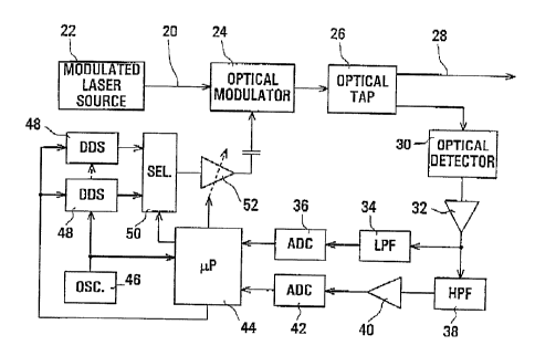
Fig, 4 illustrates one form of dither tone generator
and modulating arrangement which can be used in an embodiment
of the invention. Referring to Fig_ 4, an optical channel is
provided on an optical fiber or path 20 from a modulated laser
source 22, and is supplied via an optical mqdulator 24 and an
optical tap 26 to an ongoing optical path 28. The source 22
provides the optical channel at a desired optical wavelength
and modulated with data to be carried by the optical channel,
typically at a high bit rate of for example 2.5 Gb/s. The data
modulation can alternatively be carried out separately from the
s4urce 22, for example on the optical path 20, or using the
optical modulator 24, or on the optical path 28 after the
optical tap 26, the optical modulator 24 in the latter case
modulating an optical carrier for the optical channel. in any
event, the optical modulator 24 provides intensity modulation
of the optical channel for channel identification as described
below.
The optical tap 26=sugplies a small portion, e.g. 5%,
of the optical output of the modulator 24 to an optical
detector 30, whose electrical output is aniplified by an AGC
(automatic gain controlled) amplifier 32. An output of the
amplifier 32 is supplied via a low pass filter (LPF) 34 to an
analog-to-digital converter (ADC) 36, and via a band pass or
high pass filter (HPF) 38 and an amplifier 40 to an ADC 42.
The ADCs 36 and 42 produce digital signals which are supplied
to a digital signal processor or micrQproc,essor ( P) 44_
An qsGillator 46 provides a stable source of a
signal, for example at a frequency of 50 MHz, which is supplied
to the microprocessor 44 and to each of a plurality of direct
digital synthesizers (DDSs) or other programmable frequency
sources 48. Each DDS 48 is arranged tv produce, under
CA 02358382 2001-10-05
Oct-05-01 04:43pm From-Tropic Network T-066 P.021/034 F-364
17
programmed control of the microprocessox 44, a respective one
of the dither tones on a respective input to a selector 50. An
output of the selector 50 is coupled via a controlled gain
amplifier 52 and a capacitive coupling to a control input of
the optical modulator 24. The selector 50 and the gain of the
amplifier 52 are controlled by the microprocessor 44.
In operation, each DDS 4$ is arrzinged to prQduce
continuQusly a respective one of the dither tones to be used
for identification of the respective optical channel; for
example the dither tones fia and flb for the optical channel XI
as described above can be produced each by a respective one of
two DDSs 48 at the source of this optical channel. The
selector 50 is controlled by the microprocessor 44 to
alternately select these dither tones with the periodicity t as
described above, whereby these tones are modulated onto the
optical ohannel by the optidal modulator 24. In the case of
more than two dither tones used for channel ideritification,
there is a correspondingly increa$ed number of DDSs 48 and
select4r inputs, and the $electQr Sq is controlled by the
microprocessor 44 to select the respective dither tones in a
cyclically repeating periodic sequence.
The LPF 34 and ADC 36 provide a DC feedback path to
the microprocessor 44, and the HPF 34, amplifier 40, and ADC 42
provide a feedback path to the microprocessor 44 for the
frequency band of the dither tones, in aocordance with which
the microprocessox 44 controls the gain of the amplifier 52 to
maintain a desired constant depth of modulation by the optical
modulator 24. For example, the modulation depth may be about
4%. The use of a constant modulation depth for channel
identification facilitates determining optical power levels in
the wDM network in known manner.
CA 02358382 2001-10-05
Oct-05-01 04:44pm From-Tropic Network T-066 P.022/034 F-364
18
Although Fig. 4 represents an arrangement for only
one optical channel, it can be appxeciated that the same
arrangement can be provided for each optical channel, and that
parts of these respective arxangements may be common for
multiple optical channels. For example, it can be appreciated
that the ADCs 36 and 42 and the microprocessor 44 can be
multiplexed for operatioz7 for a plurality of optical channels,
the oscillator 46 can be used in comlt-on for all of the optical
channels, and only as many DDSs 48 are required as the number
of dither tones used for identifying the respective optical
channels.
In this respect, it is Qbserved that a particularly
convenient arrangement can be provided by ;providing all of the
components of Fig. 4, except the modulated laser source 22, for
each of a plurality of qptical channels which are initially
multiplexed by an optical multiplexer (similar to the
multiplexer 10 of Fig. 1) at the inputs of this multlpleXer.
This facilitates implementation of the arrangement of Fig. 4
with the multiplexed operation as described above for the
plurality of optical channels, while enabling the optical
channels to be supplied from arbitrary modulated laser sources
such as the source 22. More generally, it can be appreciated
that the dither tones can be applied to any optical channel
anywhere between its source and its multiplexing with one or
more other optical channels.
Fig. 5 illustrates a corresponding dither tone
detection arrangement, which may be used at any desired point
in the optical WDM netwQrk for identifying an optical channel
on an optzcal fiber or path 60 by detecting the dither tones.
Referring to Fig. 5, an optical tap 62 supplies a
small portion, e_g_ 5%, of an optical signal on the path 60 to
CA 02358382 2001-10-05
Oct-05-01 04:44pm From-Tropic Network T-066 P.023/034 F-364
].9
an optical detector 64, and supplies most of the optical signal
power to an ongoing optical path 66. An electrical output of
the aptical detector 64 is amplified by a controlled gain
amplifier 68, an output of which is supplied via a band pass
filter (BPF) 70 and an amplifier 72 to an ADC 74. The BPF 70
has a pass band including the dither tone frequerlcy range_ The
ADC 74 produces a digital signal which represents detected
dither tones and is supplied via a FzFO (first-in, first-out
store) 76 to a digital sigTaa.l processor or microprocessor 78.
The microprocessor 78, which has an associated memory 80,
contr4ls the gaill of the amplifier 68 in accordance with the
power of the optical signal on the path 60.
The microprocessor 78 operates in known manner to
perform FFT processing of the digital signals provided by the
ADC 74, using the memory 80 for this FFT processing, in
respective FFT periods T to detect any dither tone modulation
of the optical signal on the optical path 60, with the FTFO 76
ensuring that data is not lost during FFT processing by the
micrqprocessor 78. As discussed alav4e, this determines tha
respective dither tones, and hence the optical channel
identification; in one FFT operation in many instances of
typical optical signal power levels. For ensuring detection of
dither tones for relatively low power optical channels even in
the presence of one or more relatively high power optical
channels on the path 60, without increasing the FFT period T,
cQherent averaging of the FFT results is carried out over a
pluxality, possibly a large number, of successive FFT periods T
as described above.
As indicated above, there is no requirement for
synchroniza.tion between, for example, the operation of the
selector 50 in the dither tone generation arrangement of Fig. 4
CA 02358382 2001-10-05
Oct-05-01 04:44pm From-Tropic Network T-066 P.024/034 F-364
and the FTT periods of the microprocessor 78 in the detection
arrangement of Fig. 5. The continuous ger.ieration of each
dither tone eftsures that, regardless of the particular timing
of the selection of this dither tone by a selector such as the
5 selector 50, and regardless of the particular relati-ve timing
of the FFT periods T used in a detection arrangement, the
coherent averaging over a plurality of such FFT pexiods will
gradually result in accumulated results properly representing
any dither tones which are present. As indicated above, such
10 coherent averaging comprises an accumulation of the FFT
frequency bin results, or s.mplitudes in accordance with their
respective phase differences for successive FFT periods, these
phase differences being determined by the microprocessor 78 of
the detection arrangement from the dither tone frequencies and
15 the kilown period t.
As indicated above, it is conceivable to replace the
alternating dither tones, as described above for identification
of each optical channel, by some other combination, such as a
s mmatipn,, of these dither tones, for example by replacing the
20 selector 50 of Fig. 4 by a signal combiner or summer. However,
as also indicated above, this is not preferred because it
results in relatively incrcased modulation depth of each
optical channel, with corresponding eye closure for detection
of the high speed data signal carried by the optical channel.
2n addition, although the description ab~ve .relates
to an aptiGal wDM network in which optiaa.1 channels are
identified by having thei,r intensity modulated with a
combination of a plurality of dither tones,, it can be
appreciated that similar principles can be applied to
identifying and detecting multiple channels in networks and
CA 02358382 2001-10-05
Oct-05-01 04:45pm From-Tropic Network T-066 P.025/034 F-364
21
systems using othex tXpes of communications media and
modulation methods.
Thus although particulsj~ embvdimernts of the invention
are described above, it can be appreciated that these and
numerous other modifications, variations, and adaptations may
be made without departing from the scope of the invention as
defined in the claims.