Note: Descriptions are shown in the official language in which they were submitted.
CA 02358444 2001-05-09
WO 00/28199 PCT/AU99/00988
1
TWO-STROKE ENGINE
This invention relates to engines.
This invention has particular application to methods of
and apparatus for converting standard four-stroke engines into
efficient two-stroke engines. However this invention is not
limited to converting engines and may be applied to the
original production of an efficient two-stroke engine.
There are prior disclosures of two-stroke engines which
utilise power cylinders charged from a pumping chamber to
provide increases in efficiency. However inherent in such
proposals is the high cost of re-tooling for an all new engine
design. Furthermore it is considered that many of these earlier
proposals may not meet the stringent emission standards now
required of most internal combustion engines. For example, it
is very desirable to reduce emissions of oxides of nitrogen
(NOx) and particulates including soot. Efficiency in terms of
such emission reductions can be more important than fuel
efficiency or achieving power gains.
The existing engine industry is large, mature, stable and
conservative. The barriers to entry for even modest changes
to engine design are formidable. Engine buyers are committed
to existing engines and engine design. They are tooled up with
expensive plant and equipment for conventional engines and
are more likely to accept technological advances of an
incremental nature, as opposed to radical departures.
This invention in one aspect aims to provide methods of
and apparatus for converting standard four stroke engines into
two-stroke engines which may operate efficiently in terms of
selected or all exhaust emissions, fuel efficiency and power
output from the converted engine. This invention also aims to
provide engines which are useful and which have commercial
appeal to both manufacturers and users.
CA 02358444 2001-05-09
WO 00/28199 PCT/AU99/00988
2
With the foregoing in view this invention in one aspect
resides broadly in a method of converting a four-stroke reciprocating
piston engine into a two-stroke engine including:-
providing a reciprocating positive displacement pump
having a respective pumping chamber for groups of at least
two cylinders of the engine, each pumping chamber having a
displacement swept by its pumping piston which is greater than
the swept cylinder displacement of each cylinder of the engine;
securing the pump to a mounting on the engine adjacent
the cylinders whereby the outlet from the pump is located
closely adjacent the inlets of the engine;
arranging the crank pins for each group of cylinders at
angular spacings of 360 divided by the number of cylinders in
the group.
providing step-up drive means for driving the pump from
the engine, the step-up being in the ratio of the number of
cylinders in each group of cylinders of the engine per pumping
chamber;
providing relatively short feed passages through transfer
manifolding interconnecting the outlet from each pumping
chamber to the inlets of the group of cylinders to be fed
thereby, and
timing the connection between the engine and the pump
and the operation of the inlet and exhaust valves of the engine
such that:
the or each pumping piston leads alternate ones of the
power pistons fed thereby to their respective Top Dead Centre
(TDC) positions;
the inlet valve to each power cylinder to be fed opens
before Bottom Dead Centre (BDC) and closes before TDC, and
the outlet valve from the fed power cylinder opens before
BDC and closes before TDC.
CA 02358444 2001-05-09
WO 00/28199 PCT/AU99/00988
3
Preferably:-
the or each pumping piston leads alternate ones of the
fed power pistons to Top Dead Centre (TDC) position by 80 to
160 of crankshaft rotation;
the inlet valve to the power cylinder to be fed opens in
the range 50 to 00 before BDC;
the inlet valve to the power cylinder to be fed closes in
the range 70 to 160 before TDC of crankshaft rotation;
the outlet valve from the fed power cylinder opens in the
range 1100 to 40 before BDC, and
the outlet valve from the fed power cylinder closes in the
range 1000 to 180 before TDC of crankshaft rotation.
In the above ranges the timings closer to BDC would be
more suitable for engines which operate at relatively low
operating speeds and particularly large engines. High speed
engines would advantageously operate at the other end of the
range.
For a typical two litre automotive diesel engine converted
or operating to this cycle and optimised to operate at a
synchronous speed of 1500 RPM for driving a 240V alternator
for example, the typical timings would be:
the pumping piston leads the power piston to top dead
centre by 120 ;
the inlet valve to the power cylinder to be fed opens at
40 before bottom dead centre and closes at 110 before top
dead centre;
the outlet valve from the fed power cylinder opens at 70
before bottom dead centre and closes at 140 before top dead
centre.
CA 02358444 2001-05-09
WO 00/28199 PCT/AU99/00988
4
For a typical two litre automotive diesel engine converted
or operating to this cycle and optimised for high speed, typical
timings would be:
the pumping piston leads the power piston to top dead
centre by 135 ;
the inlet valve to the power cylinder to be fed opens at
45 before bottom dead centre and closes at 1150 before top
dead centre;
the outlet valve from the fed power cylinder opens at 85
before bottom dead centre and closes at 155 before top dead
centre.
Step-up ratios of two to one for the driveshaft relative to
the crankshaft are preferred for high speed engines in order
that effective transfer of air from pump to power cylinder may
be achieved. Step-up ratios of more than two to one are
preferably limited to relatively slow speed and medium speed
engines.
Suitably the swept volume of the pumping chamber is
less than 1.6 times greater than each respective power
cylinder. For example in applications requiring modest power
gain the pumping chamber swept volume may be up to 30%
greater than the swept volume of each respective power
cylinder. In applications for high power gains the swept
volume of the pumping chamber may be up to 60% greater than
the swept volume of each respective power cylinder.
Preferably for greater emission improvements the swept
volume of the pumping chamber may be 60% greater than the
swept volume of each respective power cylinder swept volume.
Furthermore the pump components are required to
operate under much lower pressures and temperatures than
the power components and this invention enables the
components to be optimised by having the relatively robust
CA 02358444 2001-05-09
WO 00/28199 PCT/AU99/00988
components of the converted engine perform work with each
revolution while utilising less robust components for pumping
and thus providing advantages in reduction of power
consumption and an associated reduction in friction loads.
5 Preferably the transfer manifold or pump head is provided
with a discharge valve which may be driven but which is
suitably a reed valve or like pressure sensitive valve which
prevents back flow of gases from the transfer manifold to the
pump cylinder during the scavenging-intake phase of the power
cylinder. More preferably the discharge valve is located
closely adjacent the outlet from the pumping chamber
minimising the re-expansion volume and thus improving the
volumetric efficiency of the pumping chamber.
The provision of the discharge valve may trap a charge of
pressurised fresh gas downstream of the discharge valve such
that at initial opening of the inlet valve and before closing of
the exhaust valve a positive flow of fresh gas is injected from
the inlet manifold to enhance scavenging of the exhaust gases.
This provision can also be utilised to inhibit the back flow of
spent gases from the power cylinder via the transfer port and
transfer manifold into the pump cylinder.
The transfer manifold from the pump to the group of
cylinders may include a single upstream branch connected to
the pump and communicating with a plurality of downstream
branches with the cylinders of the group. In such an
application a single discharge valve, such as a reed valve, may
be utilised in the upstream branch for simultaneous
communication with all downstream branches.
However it is preferred that the discharge valve be of a
type which may be controlled to communicate in a sequential
manner with alternate ones of the downstream branches.
This will minimise the effective volume of the passage between
CA 02358444 2001-05-09
WO 00/28199 PCT/AU99/00988
6
the pump and the respective cylinders for more efficient gas
transfer. Preferably the discharge valve is a timed rotating
drum valve which is disposed as close as possible to the pump
piston crown at top dead centre and which provides sequential
communication with the downstream branches.
Deflector means may be provided in the inlet tract or
valve shrouding or the like may be provided to induce loop type
scavenging of spent exhaust gases.
It is also preferred that a reed valve or other valve means
be arranged in the inlet tract to the or each pumping chamber
to assist in enhancing volumetric efficiency of the pumping
chambers.
In order to provide the required crankshaft/driveshaft
timing the group of cylinders being fed by the one pump
cylinder must have their associated crank pins at angular
spacings of 360 divided by the number of cylinders in the
group. Accordingly the converted engine may require
crankshaft modifications to achieve this configuration. The
camshaft will require new 'timings' to suit. The camshafts will
benefit from modified lift profiles to suit the shorter
exhaust/inlet phase this may also require other valve train
modifications, such as spring rates. Furthermore, the oil pump
may be modified to accommodate a larger oil circuit to include
the bolt on pump and to maintain pressure at a lower engine
idle.
It is preferred that for balance purposes respective pairs
of cranks, of converted engines having multiples of two
cylinders, be evenly offset from one another. That is in a
conventional four cylinder engine which has the cranks
contained in a common plane, the front and rear pairs of
cranks be offset at 90 to one another to producing a firing in
CA 02358444 2001-05-09
WO 00/28199 PCT/AU99/00988
7
the converted engine at every 900 of one revolution of the
crankshaft.
In another aspect this invention resides broadly in a two
stroke reciprocating engine having head mounted inlet and
outlet valves and an external pump for charging the cylinders,
wherein:-
the external pump is a reciprocating positive
displacement pump having a respective pumping chamber for
groups of at least two cylinders of the engine, each pumping
chamber having a displacement swept by its pumping piston
which is greater than the swept cylinder displacement of each
cylinder of the engine;
the pump is secured to a mounting on the engine
adjacent the cylinders whereby the outlet from the pump is
located closely adjacent the inlets of the engine;
the crank pins for each group of cylinders are arranged at
angular spacings of 360 divided by the number of cylinders in
the group.
step-up drive means is provided for driving the pump
from the engine, the step-up being in the ratio of the number of
cylinders in each group of cylinders of the engine per pumping
chamber;
relatively short feed passages are provided through
transfer manifolding interconnecting the outlet from each
pumping chamber to the inlets of the group of cylinders to be
fed thereby, and
the connection between the engine and the pump and the
operation of the inlet and exhaust valves of the engine are
timed such that:
the or each pumping piston leads alternate ones of the
power pistons fed thereby to their respective Top Dead Centre
(TDC) positions;
CA 02358444 2001-05-09
WO 00/28199 PCT/AU99/00988
8
the inlet valve to each power cylinder to be fed opens
before Bottom Dead Centre (BDC) and closes before TDC, and
the outlet valve from the fed power cylinder opens before
BDC and closes before TDC.
In an engine with four or more cylinders, to prevent the
exhaust pulse or phase of one cylinder from interfering with the
scavenging phase of another cylinder, separate exhaust
manifolds, or a manifold of a type which prevents interference
of the exhaust phase with the scavenging phase, is provided.
In the case of a turbocharged engine separate turbocharger
inlets are provided or a dividing scroll is provided in the
turbocharger inlet. Alternatively, separate turbochargers may
be utilised.
In order that this invention may be more readily
understood and put into practical effect, reference will now be
made to the accompanying drawings which illustrates a typical
embodiment of the present invention and wherein:-
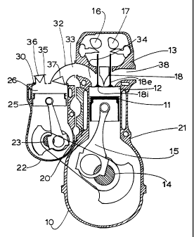
FIG. 1 is a diagrammatic end view of a conventional
multi-cylinder four stroke engine adapted to operate as a
two stroke by the apparatus of the present invention;
FIG. 2 illustrate the phases of the operating cycle; FIGS.
3 and 4 illustrate typical arrangements for port deflecting
and valve shrouding, and
Fig. 5 is a graph of Pressure V Time for the transfer
manifold.
Referring initially to Fig. 1, it will be seen that a typical
multi-cylinder four stroke engine 10 has pistons 11 arranged
for reciprocation within cylinders 12 to and from a cylinder
head assembly 13 which supports poppet valves 18 for control
of fluid to and from the respective cylinders 12.
The pistons 11 are driven through a crankshaft 14 and
are connected thereto by connecting rods 15. Overhead
CA 02358444 2001-05-09
WO 00/28199 PCT/AU99/00988
9
camshafts 16 and 17 are driven from the crankshaft in a timed
relationship therewith whereby the poppet valves 18 control the
four stroke process.
According to the present invention, such multi-cylinder
four stroke engines are readily modified for operation as a two
stroke engine by providing a mounting, and suitably in the form
of an adaptor plate 20 at one side wall of the engine block 21
which is provided with threaded apertures to support a bolt-on
reciprocating pump 22.
The pump 22 has a crank shaft 23 driven from the engine
crankshaft 14 at twice the speed of rotation thereof whereby
the piston 25 of the bolt-on pump reciprocates at twice the
cycle speed of the pistons 11 of the engine 10. The bolt-on
pump 22 provides one piston 25 and pumping chamber 26 for
each two of the cylinders 12 of the engine 10 in which the
pistons 11 reciprocate.
The bolt-on pump 22 is mounted with its cylinder head 30
mounted as close as practicable to the inlet openings through
which the air inlet manifold normally connects so that relatively
short transfer passages 32 may be arranged between the outlet
port 33 from a respective pumping chamber to a pair of inlet
ports, one of which is shown at 34 of the engine 10.
An inlet passage 35 is provided to the bolt-on pump 22
and non-return valves, suitably reed valves 36 and 37 are
arranged in the inlet passage 35 and the transfer passage 32.
Flow through the transfer passage is also controlled by the
inlet poppet valve 18i and it will be seen that the inlet
poppet valves 18i and the reed valves 37 are disposed near to
the ends of the transfer passage 32. A further valve 1 8e is
provided for each exhaust port 38 from the respective cylinder
12 in conventional manner, however the timing of the valves 18
is modified for two stroke operation.
CA 02358444 2001-05-09
WO 00/28199 PCT/AU99/00988
The inlet valve 1 8i or port 34 may require shrouding as
shown in Figs. 3 and 4 to direct the incoming air causing more
efficient scavenging and reducing short circuiting and the
cooling system may need a higher heat rejection rate, including
5 higher flow rate water pump, and larger radiator. If desired,
the original four stroke inlet port may need to become the
exhaust port and vice versa.
The bore and stroke of the bolt-on pump provides a
swept volume for each pumping chamber which is greater than
10 the swept volume of each power cylinder 12 and for high power
applications the swept volume of each pumping chamber may
be 1.6 times the swept volume of each power cylinder 12.
The pumping chamber is timed relative to the power
cylinder so that the respective pumping piston 25 reaches its
top dead centre position in advance of the piston 11 in the
power cylinder 12 into which a charge is being induced. In the
illustrated embodiment, the pumping piston 25 reaches its top
dead centre position while the power piston 11 is arranged at
about 120 before its top dead centre position in the respective
cylinder 12. The illustrated embodiment is a diesel engine
which has injectors (not illustrated) which
inject fuel directly into the combustion chamber.
In use, the bolt-on pump 22 is provided with a one way
flow reed valve 36 in its inlet passage 35 such that during the
downstroke of the piston 25 and continuing until beyond bottom
dead centre, air is induced into the respective pumping
chamber 26 above the piston 25 and then discharged therefrom
through the one-way valve in the form of the reed valve 37
located at the entrance to the transfer passage 32. A rotary
valve or a poppet valve could be used in lieu of a reed valve if
desired.
CA 02358444 2001-05-09
WO 00/28199 PCT/AU99/00988
11
The inlet valve 18i to the respective power cylinder 12
opens at about 400 before bottom dead centre of the pump 22
and closes during the upstroke of the piston 11 so that
compression occurs during movement to top dead centre when
fuel is injected and combustion occurs to provide a power
stroke as the piston 11 moves down the cylinder 12 towards its
bottom dead centre position.
The exhaust valve 1 8e then opens and exhaust gases are
discharged therethrough as the piston continues beyond the
bottom dead centre position and part way up the following
compression stroke. Prior to closure of the exhaust valve 18e,
the inlet valve 1 8i is opened and air trapped between the inlet
valve 18i and the reed valve 37 in the transfer passage 32 and
which is at a higher pressure than the residual exhaust gases
at its time of opening so that the air trapped is forced into the
cylinder 12 assisting with the scavenging of the exhaust gases.
This effect is illustrated in the graph of Fig. 5 wherein it
will be seen that subsequent to the pump 22 raising the supply
pressure, the reed valve 37 closes and traps pressurised air in
the transfer manifold 32, demonstrated by the cross-hatched
area.
The inlet valve 18i remains open so that the new charge
induced into the pump 22 is forced into the combustion
chamber for compression and repeat of the process described
above.
In the embodiment illustrated in Fig. 1, the timing
arrangements as illustrated in Fig. 2, are such that the
pumping piston 25 reaches its top dead centre position when
the respective power piston 11 is at 120 before top dead
centre in the cylinder 12. The intake valve 18i is adapted to
open at 40 prior to bottom dead centre of the piston 11 and
close at 110 before top dead centre. The exhaust valve 1 8e is
CA 02358444 2001-05-09
WO 00/28199 PCT/AU99/00988
12
adapted to open at 70 prior to bottom dead centre of the
piston 11 and close at 1400 prior to top dead centre of the
piston 11 . Diesel fuel is injected at 16 .
Furthermore the bolt-on pump has a swept capacity
which is 1.4 times the swept capacity of each of the cylinders
12 of the engine 10.
This engine can be expected to operate efficiently as a
two stroke engine producing up to 1.7 times the power of the
original four stroke engine.
Preferably for a four cylinder engine, the bolt-on pump is
a two cylinder pump having pistons 180 out of phase with
one another and the crankshaft 14 of the conventional
engine is modified by arranging the cranks of each group of
two adjacent cylinders at 180 displacement from one another
and with the two groups of cranks being displaced 90 from
one another so as to provide a firing order of 1324.
By converting a conventional four stroke engine to a two
stroke engine according to this invention the original torque
and power output per unit of engine swept volume of the
converted engine should be significantly increased. It is
considered that torque and power output increases of up to
100% may be achieved for a converted four stroke engine.
Furthermore, power-to-weight and power-to-volume ratios
are also enhanced and achieved with a weight penalty of 5%-
10% of base engine weight, and being mostly the additional
weight of the pump which performs a pumping function only
and is not subject to combustion forces and thus may be
relatively lightweight construction.
Thus it is expected that in a converted four stroke engine
output gains of 70% may be achieved with a converted engine
that is 30% lighter and 25% smaller in overall package volume
CA 02358444 2001-05-09
WO 00/28199 PCT/AU99/00988
13
than a comparable four stroke reciprocating combustion
engine.
As each cylinder of the converted engine fires twice as
often as the original the fuelling rate per combustion event may
be reduced or the air/fuel ratio is leaned. This should have the
effect of lowering the peak cycle temperature and residence
time at high temperatures. This lowers production of NOx and
the greater oxygen availability reduces production of
particulates and smoke.
Additionally, high levels of small and microscope turbulence
will be present before and during the combustion event to
assist in efficient combustion. This will result from the high
rate of mass flow of the scavenging air past the inlet valve
because the majority of incoming charge air is transferred in
less than 900 of crank rotation and because of its late
admission in the cycle which results from most air being
transferred after bottom dead centre of the power piston.
In this respect in a four stroke engine the small and
microscope turbulence generated during induction mostly
decays by the time combustion is initiated. In a converted
engine according to this invention it is considered that the
turbulence will be more intense than usual and created later in
the engine cycle than usual resulting in substantial turbulence
existing at combustion initiation.
This effect should manifest itself in significant reduction
in spark advance or diesel injection advance requirement.
It is considered that the timing advance BTDC required
for best torque in both petrol and diesel may be reduced from
about 30 to 12 injection from about 30 - to 16 - respectively.
In the diesel this may also significantly reduce the premixed
phase of combustion and a consequent reduction in the rate of
CA 02358444 2001-05-09
WO 00/28199 PCT/AU99/00988
14
pressure rise and thus a reduction in production of NOx and
noise.
It is also considered that because the scavenge air is
delivered in a rapid pulse, as the pump piston is working at
twice the cyclic rate of the engine pistons, increases in the
mean velocity of the scavenge air will increase scavenging
effectiveness. As the scavenge air is delivered relatively late
in the cycle, the fresh charge short circuiting straight to
exhaust will be minimised. Thus efficient scavenging should
occur.
A converted engine of this invention will generally run
lower cylinder pressures, but twice as many combustion
events, and the individual pressure peaks will be lower and the
individual torque pulses on the connecting rods and the
crankshaft will be lower and more numerous, reducing torque
fluctuation. Thus components such as crankshafts and
bearings, connecting rods, cylinder head gaskets and piston
ring groups which are designed to withstand normal four stroke
loadings should have a similar or longer life expectancy.
It will be seen that this invention provides a bolt-on
system for modifying engines which manufactures are set up to
manufacture and which potentially provides substantial
technical benefits while minimising the impacts on existing
production technologies and facilities, staff retraining and R&D
effort required for production. The conversion is suitably
undertaken by existing engine manufacturers or at least
partially during basic manufacture. However it can of course
be performed by others.
The conversion utilises relatively low cost, well proven
reciprocating piston componentry and is capable of being
bolted on to production 4-stroke engines with a minimum of
component and manufacturing plant and equipment changes.
CA 02358444 2001-05-09
WO 00/28199 PCT/AU99/00988
Thus should a manufacturer desire to enter a new larger kW
market or assist in compliance with emission regulations, the
manufacturer can provide a converted version of his existing
engine according to this invention for that new market.
5 The manufacturer can utilise existing R&D knowledge,
and need only make modest alterations to their production
facility. In most cases the production facility will have
sufficient capacity and flexibility to produce both the existing
and converted engines of the present invention, so the
10 production output break even point for both engines will be
greatly reduced. Staff retraining is also minimised along with
supplier sourcing problems
In addition to supplying the pump and transfer manifold
the manufacturer will be required to adapt a mounting. and
15 drive for the pump. The drive may be from the crankshaft at
the front or the rear of the engine, or from any point along the
engine crankshaft. The drive means may be of any type,
requiring only that connection be suitably timed in operation. If
desired the drive connection between the crankshaft and the
driveshaft may be of a type in which the phasing is adjustable
in use to suit the particular operating conditions. For example,
at high load and high RPM, the phasing of the driveshaft may
be advanced relative to the crankshaft such that the
scavenging efficiency may be optimised.
The engine exhaust manifold may be modified to contain
dividers or scrolls to separate the individual cylinder exhaust
pulses however cylinders out of phase may share common
exhaust manifold volume.
The exhaust ports may require additional cooling if they
do not have sufficient heat rejection ability they may be
insulated by ceramic port coatings.
CA 02358444 2001-05-09
WO 00/28199 PCT/AU99/00988
16
Suitably the area of the engine for adaptation of the
pump should contain provision for bolting or securing the pump
thereto, such as studs or threaded holes or the like fixings.
Preferably the area is a surfaced area or face for bolting and
sealable ports are provided through which an internal drive is
possible. The mounting area may also contain oil supply and
return means and cooling water supply and return means.
The provision of a single pump cylinder feeding two
power cylinders has the advantage that the pump piston is
working at twice the cycle rate of the power pistons. This
increases the mean velocity of the fresh charge being
introduced into the power cylinder which is delivered late in the
exhaust cycle thus minimising loss of fresh charge by short
circuiting straight to the open exhaust valve.
The increased flow velocity may also have the beneficial
effect of increasing turbulence of the incoming charge and at
combustion initiation. It is further considered that this will
enable stable idling speeds to be substantially reduced
providing further economies.
It will of course be realised that the above has been given only by
way of illustrative example of this invention and that all such and other
modifications and variations thereto as would be apparent to persons
skilled in the art are deemed to fall within the broad scope and ambit of this
invention as is defined in the appended claims.