Note: Descriptions are shown in the official language in which they were submitted.
CA 02358449 2001-07-16
WO 00/42946 PCT/CA00/00035
EXPANDABLE INTRAVASCULAR TUBULAR STENTS
BACKGROUND OF THE INVENTION
Following an angioplasty procedure, the restenosis rate of stented vessels has
proven
significantly lower than for unstented or otherwise treated vessels, which
treatments include
drug therapy and other surgical procedures.
The intravascular stmt functions as scaffolding for the lumen of a vessel. The
scaffolding of
the vessel walls by the stmt serves to: (a) prevent elastic recoil of the
dilated vessel wall;
(b) eliminate residual stenosis of the vessel, a common occurrence in balloon
angioplasty
procedures; (c) maintain the diameter of the stented vessel segment slightly
larger than the
native unobstructed vessel segments adjacent the stented segment; and (d) as
indicated by the
latest clinical data, lower the restenosis rate.
The conventional stmt designs suffer in varying degrees from a variety of
drawbacks
1 ~ including: (a) the inability to negotiate bends in vessels due to columnar
rigidity of the
unexpended stent; (b) the lack of structural strength, both radial and
bending, of the
unexpended stent; (c) significant foreshortening of the stmt during expansion;
(d) limited stmt
length; (e) constant expanded stmt diameter; (fJ poor crimping
characteristics; and (g) rough
surface modulation of the unexpended stent.
Although many stems are made of wire which is wound and bent into desired
configurations,
stems may also be formed using thin-walled tubes that are laser cut, or
otherwise formed to
allow the tubes to be compressed into a smaller diameter for delivery to a
desired location
within a body lumen. Such stents, commonly referred to as tubular stems,
provide advantages
in terms of increased torsional stability and hoop strength as compared to
stems formed from
wires. One disadvantage, however, is that tubular stems typically exhibit
limited longitudinal
flexibility which can limit delivery through tortuous pathways and their
deployment in cmroed
body lumens.
CA 02358449 2001-07-16
WO 00/42946 PCT/CA00/00035
2
As a result, a need exists for a stmt that provides the longitudinal
flexibility associated with
wire-wound stems in combination with the hoop strength and torsional stability
of a tubular
stmt.
A review article, Does Stent Design Influence Restenosis?, by Dr. J. Gunn
published in the
European Heart Journal July 1999 (Vol. 20, issuel4), stated that unlike
restenosis after
balloon angioplasty, the in-stmt restenosis consists predominantly of
neointimal growth rather
than the combination of neointima, recoil and downsize remodelling seen after
the balloon
angioplasty. The degree of restenosis is related to the extent of damage done
at the time of
implantation. The composition of the neointima of in-stmt restenosis is
similar to that seen
in balloon angioplasty, and includes vascular smooth muscle cells and inter-
cellular matrix.
Any subtle differences in the composition of the neointima of the in-stmt
restenosis and post
-balloon injury, for example a suggestion of more matrix relatives to cell in
the former, may
be explained by the different nature and time-course of the two injuries: stmt
struts produce
local deep trauma, and the stmt as a whole produces chronic stretch; whereas
balloon injury,
which may also be deep, is transient an tends to be focal, with unilateral
dissection rather than
circumferential stretch. There is clinical evidence that the stmt geometry
influences in-stmt
restenosis. One widespread perception is that tissue prolapse at the central
articulation of the
Palmaz-Schatz stmt (U.S. Patent No. 5,382,261 to Palmaz dated January 17,
1995) increases
in-stmt restenosis at that site. Intravascular ultrasound has also revealed
that in-stmt
restenosis within coil-stems is related to recoil, whereas in-stmt restenosis
within slotted tube
stems is related to sub-expansion. In a retrospective study of matched lesion,
the flexible
Micro StentTM from Arterial Vascular Engineering, Inc. of Santa Rosa,
California., was
associated with a higher restenosis rate than the more rigid Palmaz-Schatz
stmt. Similarly,
a coil-stmt has been shown to be associated with increased in-stmt restenosis
compared with
a slotted tube stmt in chronic total occlusions, a situation where radial
strength is probably
paramount.
In one systematic study, where the features of stmt geometry which make one
stmt superior
to another were investigated, changing the stmt configuration to reduce strut-
strut intersections
reduced the vascular injury score by 42%, thrombosis by 69% and neointimal
hyperplasia by
38%. Coating with an inert polymer did not alter vascular injury or neointimal
hyperplasia,
although thrombosis was eliminated. Uniform (modest oversize) deployment of
multiple
examples of one design of stmt in normal porcine coronary artery, with many
sections
analysed at a consistent time point, allows precise mathematical analysis of
the relationship
CA 02358449 2001-07-16
WO 00/42946 PCT/CA00/00035
3
between as many parameters of the stmt geometry as are thought useful in in-
stmt restenosis.
Using this technique, extreme strut protrusion, large inter-strut distance,
fracture ofthe internal
elastic lamina, medial compression and location near the distal ends of the
stmt have been
identified as of particular importance. There was no direct relationship found
between the
number of struts and in-stmt restenosis unless the stmt was over-deployed, in
which case
more struts were advantageous, presumably distributing the forces of stretch
more evenly and
preventing isolated strut protrusion. In the same study, there was great lumen
loss and
neointimal growth at the distal end compared with the middle of the stems,
possibly reflecting
the taper seen in a porcine artery. There was suggestion that eccentricity of
the stmt
deployment (oblateness of the cross-section) adversely affected in-stmt
restenosis. There is
clinical intravascular ultrasound-based evidence for this, too. In one study,
deviation from
the circular in a stented vessel is associated with a trend towards increased
target vessel
revascularization at long-term follow-up. In contrast to the early days of
stenting, when the
fear of a "foreign body" reaction was still present, results such as this now
point away from
a minimalist approach towards generous coverage of the wounded vessel wall,
with a high
metal/artery ratio. The concept of maximizing the metal barrier is, of course,
limited by poor
"crimpability", unacceptable profile and inflexibility. Such designs (for
example, the Jomed
covered stmt made by Jomed Implantate GmbH of Rangendingen, DE) are already
marketed,
but have not yet reached wide acceptance.
Deployment strategies are also likely to affect the long-term result of
stenting. Finite element
analysis has revealed that low balloon compliance and the lowest possible
balloon pressure to
achieve adequate deployment are important variables. Balloon -(and stmt)-
artery ratio (BAR)
are also contributory. In his early studies, Schwartz ( J Am Coll Cardol
1992;19:267-274)
used a BAR of 1.5:1, and produced dramatic injury with a high experimental
animal mortality
rate. Thomas (Jlnvas Cardiol 1997;9:453-460) , however, using a BAR of 1.1: l,
experienced
100% patency and minimal neointima. In trying to draw any conclusion from the
data
available about the "ideal" stmt, a pattern is starting to emerge. Whilst
preserving the
desirable characteristics of low profile, trackability, conformability and
visibility, a stmt
should have many, closely spaced struts giving good, well-distributed radial
strength. The
inter-strut connections, whilst allowing for even balloon expansion and access
to
side-branches, should form a close meshwork which prevents large spaces from
opening up
between the struts, or from one strut protruding radially beyond its
neighbours. The forces for
expansion should be distributed evenly so that the stmt expands symmetrically,
without
CA 02358449 2001-07-16
WO 00/42946 PCT/CA00/00035
4
eccentrity. Attention should be paid to the design of the ends of the stmt, so
that a smooth
transition to normal vessel is created, and distal oversizing is avoided. The
design should
preclude the development of large defects in metal coverage. Sizing of the
stmt relative to the
normal "reference" segment should not be over-zealous, especially where a long
stmt is used.
The diameters of some preferred stems, when in the compressed state for
delivery to a desired
location within a body lumen is typically from about two to about three times
less than the
diameter of the stems when in their expanded state. For example, typical stems
may have a
compressed external diameter of about 1 millimeter to about 3 millimeters for
delivery and an
expanded external diameter in a body lumen of about 3 millimeters to about 15
millimeters
when released from compression in a large arterial vessel.
The metal surface coverage as a function of stmt diameter is calculated by
dividing the total
vessel contact metal surface area of the stmt structure by the surface area of
the vessel at any
given stent/vessel diameter. There is inverse relationship between the metal
surface coverage
and the stent expansion (the more expansion of the stmt, the less metal
surface coverage).
The two most important features of the coronary stmt are basic to its use:
flexibility is required
only during insertion and until deployment of the stmt at the target lesion.
Rigidity is required
to supply long term support to the vessel wall, but only from the moment of
deployment and
on.
In a description of the Iris stmt (which is a slotted tube stmt made of 316L
stainless steel by
Uni-Cath Inc. of Saddle Brook, New Jersey, U.S.A.) by Albert Tashji published
in the
Handbook of Coronary Stents, second edition,1998, chapter24 (see also U. S.
Patent Number
5,911,754, issued June 15, 1999), the expansion data observed is shown in
Table 1.
STENT DIAMETER LENGTH SHORTENING METAL COVERAGE
mm (inches (mm (%) %)
1 0.04 16.9 -- 55.4
2.5 0.098 16.1 4.7 21.9
3 0.118 16 5.3 18.6
3.5 0.138 15.1 10.7 17
4 0.157 14 17.2 16.2
Table 1
CA 02358449 2001-07-16
WO 00/42946 PCT/CA00/00035
The NIR stmt by SCIMED MEDTRONICS (SciMed Life Systems, Inc. of Maple Grove,
MN,
U.S.A. and Medtronics, Inc. of Minneapolis, MN, U.S.A.) is a mufti-cellular
slotted tube
design made of 316L stainless steel. The mufti-cellular design comes in two
types to cover
different vessel diameters. The 7-cell circumflex unexpended stmt will expand
by different
5 size balloons to cover vessel diameters that range from 2.Smm to 3.Smm. The
metal to artery
percentage ratio for the 7-cell will range from 24% at 2.Smm to 14% at 3.Smm
expansion and
the stmt foreshortening ranges from 7% at 3.Smm to 14% at 4.Omm expansion. In
order to
prevent further reduction of the metal to artery percentage ratio and
foreshortening of the stmt
at expansion higher than 3.Smm, a second stmt is provided where the external
diameter of the
circumflex unexpended stmt is increased to 9-cell in order to expand up to
Smm. The metal
to artery percentage ratio for the 9-cell will range from 14% at 3.Omm to 11%
at S.Omm
expansion and the stmt foreshortening ranges from 7% at 3.Smm to 14% at S.Omm
expansion
(PMA application # P980001 , published by the FDA in August 11, 1998). The
drawback of
the increase of the external diameter of the unexpended stmt will effect the
flexibility, because
there is inverse relationship between the external diameter and the
flexibility of the
unexpended stmt.
SUMMARY OF THE INVENTION
Accordingly, one object of the invention is to provide a flexible stmt which
can be easily
delivered through meandering and narrow arteries or other body lumens.
Another object of the invention is to provide the stmt as stated above, which
can substantially
prevent shortening of the entire length of the stmt when it is expanded. It is
further obj ection
of the present invention to provide a stmt which does not substantially change
in length or at
least does not reduce in length as the stmt diameter expands during balloon
expansion.
A further obj ect of the present invention is to provide a stmt with a low
profile when crimped
over a delivery balloon of the stmt assembly.
A further object of the present invention is to provide a stmt with generous
coverage of the
wounded vessel wall, with a high metal/artery ratio. It is further objection
of the present
invention to provide a stmt with a closely spaced struts giving good, well-
distributed radial
strength.
16:05 FAa 613 234 3563 MacRse & Co.
' 06-03-2001_ - _ - - - - - _ _ - ,_", _ _ - _ - . CA 000000035
" CA 02358449 2001-07-16
6
Another object of the invention is to provide the stoont with a compressed
state or uncxpand~ed
diameter for deliveryto adesired locationwithia a bodyl>imenwhich allow a
gradual increase
up to five times the initial diameter of the stmt upon expansion. It is a
ftutlur object of the
t invention to provide a ewutmlled expansion of the stmt to avoid ovetstzing
of the stmt
relative to the normal "refaa~ce" segment
Accordingly there is provided in one aspect of this invention an iatravascular
tubular stoat
expandable bvtwoea a first, constricted state and a second state of greater
expanded diameter;
the stmt coaaprisiag is its constricted state:
a plurality of radiahy expandable rings each formed of a plurality of
circum'ferentially
extendable elona~s, each cireurnf~tially axtaadable element co~aaprisin8:
at least one first functional unit having a bendable joist from which a pair
of
arms extend so as to form thezebetween an elongate opening disposed in a first
direction; and
a plurality of second functional omits each of whichhaving a bendable joint
fra~m
which a pair of arms extend so as to fear therebctween as elongate opening
disposed
in a scwad ditedion;
the first direction being substantially papa~icularto the second direction;
and
each pair of adjacent radiadly expandable rings being cotu~ected to each other
at at least
one location.
In accordance with another aspect of the invention, there is provided an
intravaseular tubular
steal expandable between a first, constricted stare and a second state of
greater Gxpaaded
diameter; the stmt comprising in its constricted state:
a plurality of radially expandable rings each formal of a plurality of
circumfaacnially
extendable elements, each circumfereatially extendable element comprising at
least one
functional wait having a bendable j oiat from which a pair of arms acGaad so
as to form an
elongate opening therebetween;
each expandable ring being disposed at as obli~ angle with respect to the
longitudinal
axis of the slant, and
each pair of adj scent radislly expandable rings being connected to each other
at at least
one location.
AMENDED SHEET
EMPFANGSZEIT 6,MAR. 22;02 Hu~uRUCKSZE1T ~ MaR ~~~n~
CA 02358449 2001-07-16
WO 00/42946 PCT/CA00/00035
7
In general, the design geometry of the subject stems is such that
substantially no shortening
of the stent occurs throughout expansion and over the viable working range of
the stmt. These
and other objects and advantages of the present invention are described in the
following
description and illustrated by way of drawings.
BRIEF DESCRIPTION OF THE DRAWINGS
Fig. 1 A is a schematic drawing illustrating a tubular stmt in its unexpended,
pre-
deployment state; and Fig. 1B is a schematic drawing similar to that of Fig.
A, but showing
the stmt in a radially expanded state;
Figs. 2A to 2C are schematic drawings showing a flattened portion of the
cylindrical
contour of the various tubular stems;
Figs. 3A through 3I are schematic drawings showing various stmt elements for
describing their mechanics during expansion;
Fig. 4A is a schematic showing a flattened portion of the cylindrical contour
of a prior
art stmt, while Fig. 4B is a schematic of a flattened portion of a stmt in
accordance with the
present invention; and Fig. 4C is an illustration of the stmt portion show in
Fig. 4B but in its
expanded state.
Figs. 5 to 1 S are schematic drawings showing alternate embodiments of the
stmt
according to the present invention as a flattened portion thereof;
Fig. 16A is a magnified plan view of a dissected and laid flat stmt prototype
made in
accordance with the present invention; Fig. 16B is a greatly enlarged detail
section of Fig.
16A; and Fig. 16C is a schematic showing a flattened portion of the stmt of
Fig. 16A but
shown in its expanded state; and
Figs. 17 to 19 are schematic drawings showing further stmt embodiments made in
accordance with the teachings of the invention.
DETAILED DESCRIPTION OF THE INVENTION
FIG. 1 A illustrates schematically a simple form of a stmt 10 shown in its
constricted state, i.e.
prior to the deployment and expansion. In general, the stmt 10 comprises a
plurality of
interconnected radially expandable rings 12 arranged coaxially so as to form a
generally
tubular structure having a longitudinal axis 14. Each pair of adjacent rings
12 is
CA 02358449 2001-07-16
WO 00/42946 PCT/CA00/00035
8
interconnected by at least one interconnection member 15. The stmt of the
present invention
is operable with two or more such rings 12, the number of which is generally
dependent on
specific structure of the rings and how they are interconnected as well as the
desired length of
the stmt. Each ring 12 comprises a series of expandable elements 16 connected
together in a
circular contour. As shown schematically in Fig. 1 B, in response to the
radially outwardly
directed expansion force of a pressurized balloon inserted through the ring
12, each expansion
element 16 expands along the generally increasing circumferential contour of
the stmt 10'.
Figs. 2A, 2B and 2C show, for explanatory purposes, specific examples of
portions of stems
10A, l OB and l OC, laid flat for illustrative purposes. Stems 10A, l OB and l
OC comprise a
plurality of coaxially-arranged annular rings 12. Each ring 12 consists of a
series of connected
elements 16- which are circumferentially expandable. Adjacent pairs of rings
12 are
interconnected by interconnecting elements 15 which can be generally linear as
shown or can
themselves be expandable or contractible longitudinally with respect to the
axis of the stmt
in response to the expansion of the rings 12. In this regard, attention is
directed to Applicant's
copending International Application No. PCT/CA99/00632 filed July 12, 1999 and
entitled
"Expandable Endovascular Medical Tubular Stent", the entirety of which is
incorporated
herein by reference, which contains illustrations of a variety of different
arrangements for the
elements that constitute the stmt.
In general, the aforementioned stems 10A, lOB and lOC and, in particular, the
extendable
elements 16, can be considered to comprise one or more "functional units" each
of which,
roughly speaking, is an element that doubles-back on itself so as to form a
pair of "arms"
which are attached at one end and separated at their other thus resulting in a
"U", "V" or "C"
shape, for example. In the exemplary stems 1 OA,1 OB and 1 OC shown in Figs.
2A, 2B and 2C,
these functional units are U-shaped and are oriented such that their "arms" or
their "openings"
are disposed either parallel with or transverse to the stmt axis 14. Figs. 3A
and 3C illustrate
such functional units 20A and 20B, respectively. Fig. 3A shows a functional
unit 20A of
length L, having a pair of generally parallel arms 22,24 connected by a
deformable or bendable
joint 26. The arms 22,24 are spaced apart a circumferential distance C, by an
opening 28.
Opening 28 as well as arms 22,24 are disposed generally parallel with the
longitudinal axis 14
of the stmt. In general, many prior art stems utilize such parallelly-oriented
functional units
or variations thereof in their construction, including Applicant's prior U.S.
Patent No.
5,755,776, issued May 26, 1998 and entitled "Permanent Expandable Intraluminal
Tubular
Stent", which is also incorporated herein by reference.
CA 02358449 2001-07-16
WO 00/42946 PCT/CA00/00035
9
Fig. 3B demonstrates the changes to the functional unit 20A' during radial
expansion of the
stmt. In general, initial deformation takes place in the bendable joint 26 and
both the arm
members 22;24 move diagonally away from each other in the opposite (i.e.
circumferential)
direction which results in an increase of the circumferential distance C,'
which results in an
overall increase in the circumference of the stmt 10 during expansion. At the
same time, the
length L of the functional unit 20A will be reduced to a length L,' which, in
turn, results in
overall foreshortening of the stmt 10.
In order to avoid the foreshortening of the functional unit 20A,20A', a change
in the
orientation is needed as shown in the functional unit 20B in Fig. 3 C in which
the arm members
22,24 are disposed generally perpendicular to the longitudinal axis 14 of the
stmt 10 and
connected by bendable joint 26 arranged generally parallel to the longitudinal
axis 14. In this
case, the axial length of the functional unit 20B is shown as Lz while its
circumferential length
is shown as C2. If the arm members 22,24 are caused to move diagonally away
from each
other, this will result (see Fig. 3D) in an increase of the length LZ of the
functional unit 20B
to LZ' which, in turn, will result in overall increase in the length of the
stmt 10. At the same
time, there will be a decrease in the circumferential length CZ of the
functional unit 20B to CZ'
which will result in a reduction of the circumference of the stmt 10 and this
reduction is at
odds with the desired capability for expansion.
To reach an optimum state between Figs. 3A and 3C, there is provided in Fig.
3E a diagonally-
oriented functional unit 20C in which the arm members 22,24 have a diagonal
orientation with
respect to the longitudinal axis 14 of the stmt 10. The arms 22,24 are
connected by a bendable
joint 26 also arranged diagonal to the longitudinal axis 14 of the stmt 10.
The functional unit
20C has a length L3 and the ends of the arms 22,24 are separated a
circumferential distance C3.
Upon radial expansion (as shown in Fig. 3F), arm members 22,24 of the
functional unit 20C'
move diagonally away from each other in the opposite direction which results
in increase of
the circumferential distance C3' which, in turn, results in overall increase
in the circumference
of the stmt 10 during expansion. At the same time, the length L3' of the
functional unit 20C'
will be at least be maintained with respect to initial length L3 or non-
significantly reduced
which will result in practically no foreshortening of the stmt 10 during
expansion.
Another alternative to prevent foreshortening of the functional unit is shown
in Fig. 3G in
which the functional unit 20D having a length L4 has its two arm members 22,24
angled
towards one another each at an angle a from parallelity with the stmt axis 14
so that the
CA 02358449 2001-07-16
WO 00/42946 PCT/CA00/00035
opening 28 is narrower at the ends of the arms 22,24 distal the bendable joint
26 than at their
proximal ends. This arrangement is termed herein as "over-parallel". The
advantage to this
over-parallel arrangement is that where the ends distal the bendable joint are
spaced an initial
circumferential distance C4, circumferential expansion initially opens the
arms 22,24 through
5 to parallelity as shown in Fig. 3H whereat the ends of the distal arms
22,24are spaced apart a
greater distance C4' while the length of the functional unit 20D' expands
slightly to L4'.
Continued radial expansion causes further widening of the circumferential
distance to C4"
(termed "under-parallel") as shown in Fig. 3I, resulting in an overall
increase in the
circumference of the stmt 10. However, as the arms 22,24 diverge from
parallel, the overall
10 length L4" of the functional unit 20D"will start to reduce from L4'. When
the angle a"= a,
length L4" will equal the initial length L4 and while there has been a
circumferential expansion
to C4", no overall shortening of the functional unit 20D has resulted. Of
course, further radial
expansion will start to foreshorten the functional unit 20D" as compared with
its original
length. Of importance, however, is that in comparing the functional units 20A
and 20D of
Figs. 3A and 3G, respectively, for a given amount of circumferential
expansion, the axial
shortening of the former will necessarily be greater than that of the latter.
Alternately stated,
for a given reduction in length of one of these functional units, a greater
circumferential
expansion can be achieved by the functional unit 20D of Fig. 3G than the
functional unit 20A
of Fig. 3A. Accordingly, these advantageous principles can be incorporated
into the design of
stents to achieve the desired minimization or elimination of axial reduction
upon
radial/circumferential expansion.
Figs. 4B and 4C illustrate the principle of the over-parallel functional unit
20D of Fig. 3G as
applied to the substantially rectilinear stmt design 40 as shown in Fig. 4A,
which is derived
from Applicant's aforementioned U.S. Patent No. 5,755,776. Stent 40 comprises
a plurality
of circular rings 12 arranged coaxially with respect to stmt axis 14. Each
ring 12 comprises
a plurality of circumferentially expandable elements 16 arranged in a
generally serpentine or
square wave-form pattern about the cylindrical contour of the stmt. The
arrangement of
circumferentially expandable elements 16 in one ring 12 is such that the
adjacent ring 12 is the
mirror opposite in the axial direction. Thus, the openings 28 of the
expandable elements 16
of one ring 12 oppose the openings 28 of the expandable elements 16 of an
adjacent ring 12,
whereas the "joints" 26 of the expandable elements 16 are disposed immediately
adjacent the
joints 26 of the adjacent ring 12. By interconnecting adjacent pairs of rings
12 by at least one
interconnecting member 15 per pair from the "bottom" 42 of an expandable
element 16 to the
CA 02358449 2001-07-16
WO 00/42946 PCT/CA00/00035
11
bottom 42 of an adjacent expandable element 16, the stmt 40 resists reduction
in length upon
radial expansion as explained in Applicant's aforementioned U.S. Patent No.
5,755,776. In
the stmt 50 shown in Fig. 4B, the joints 26 between the pairs of arms 22,24
are rounded and
the arms 22,24, which are generally linear, are angled toward one another so
as to form an
expandable element 16 with a convergent opening 28 which is the same as the
over-parallel
functional unit 20D of Fig. 3G. The expandable element 16 alternatingly
repeats itself so as
to form a serpentine or sinusoidal ring 12. Stated alternately, the arm 22 for
one expandable
element 16 is shared as one arm 22 of the circumferentially adjacent
expandable element 16
as shown in Fig. 4B. Interconnecting members 15 connects the bottom 42 of one
expandable
element 16 to an opposed expandable element 16 so as to function in the same
manner as the
interconnecting member 15 of the stmt 40 of Fig. 4A as aforesaid. Upon radial
expansion of
the stmt 50 as shown in Fig. 4C, the diverging of the arms 22,24 initially
causes each ring to
lengthen in the axial direction of the stmt SOand, only once the arms 22,24
are past parallel,
do the rings 12 start to shorten. Thus, the propensity for shortening upon
radial expansion of
the stmt 50 of Fig. 4B is even further reduced as compared with the
arrangement of Fig. 4A
in accordance with the previously discussion with respect to functional unit
20D of Fig. 3G.
Variations of the stmt 50 of Fig. 4B are shown in Figs. 5 and 6 as stems 60,70
in their
compressed (i.e. unexpanded), pre-deployment state. In Fig. 5, the ring
interconnecting
member 62 essentially takes the place of an adj acent pair of expandable
elements 16' as shown
in stippled lines. As with the arrangement shown in Fig. 4, interconnecting
member 62 serves
to reduce the longitudinal reduction of the stmt 60. The presence of the over-
parallel
functional units 20D serve to further reduce the amount of foreshortening. In
order to increase
axial flexibility, the stent 70 of Fig. 6 is provided with a relatively short
interconnection
member 64s between adjacent rings 12. Enhanced axial flexibility is important
in the
undeployed stmt to enable the stmt to be delivered to a desired location via a
tortuous vessel.
The stents 50,60,70 shown in Figs. 4B,5, and 6 comprise a plurality of the
over-parallel
functional units 20D disposed generally parallel with respect to the
longitudinal axis 14 of the
respective stmt (i.e. the openings 28 are aligned generally parallel as shown
in Fig. 3G).
However, Applicant has found as explained in his aforementioned International
Application
No. PCT/CA99/00632, that by orienting at least some of the roughly linear
components of the
circumferentially expandable elements 16 in the circumferential direction,
such as is shown
in Figs. 2A-2C, self compensation of the longitudinal shortening of the stmt
occurs due to the
longitudinal expansion of each ring 12 coupled with the reduction in distance
between adj acent
CA 02358449 2001-07-16
WO 00/42946 PCT/CA00/00035
12
rings. By orienting at least some over-parallel functional units in the
circumferential direction,
even further radial expansion is possible while still maintaining the self
compensating feature
of the stmt, thus resulting in a greater expansion range with little or no
change in the length
of the stmt over the working range.
In this regard, there is provided in Fig. 7 one embodiment of the invention
which includes a
plurality of rings 12 each comprised of a series of circumferentially
expandable serpentine
elements 16. Each expandable element 16 is comprised of a plurality of over-
parallel
functional units 20E oriented generally circumferentially or perpendicular to
the longitudinal
axis 14 of the stmt 80. Adjacent rings 12 are interconnected at selective
locations 82 whereat
the bendable joint 26 of one over-parallel functional unit 20E is integrally
formed, fused or
otherwise attached to the bendable joint 26 of an adjacent over-parallel
functional unit 20E.
In other words, the external apexes of adjacent bendable joints 26 are
attached. With this
stmt 80, each expandable element 16 is connected to the next in the series by
way of a further
over-parallel functional unit 20F oriented generally parallel to the axis 14.
Fig. 8 shows a stmt 90 which is a variation of the stmt 80 embodiment of Fig.
7 having
substantially identical rings 12 comprised of a series of expandable elements
16, each being
a horizontal mirror image to the next in the series. The rings 12 themselves
are vertical mirror
images of the adjacent ring 12. However, the rings 12 in this embodiment are
interconnected
in the same manner as the stmt 50 of Fig. 4B, that being an interconnecting
member 1 S which
extends from the bottom of one axially aligned, over-parallel functional units
20F to the
bottom of an opposed over-parallel functional unit 20F.
The stmt 100 shown in Fig. 9 is similar to the stmt 80 of Fig. 7 except that
the arms 22A,24A
of the circumferentially aligned over-parallel functional units 20E which are
on the outermost
sides of each expandable element 16 are circumferentially aligned. Between
circumferentially
adjacent expandable elements 16, an axially-aligned functional unit 20A, such
as shown in Fig.
3A is provided.
The stmt 110 shown in Fig. 10 comprises a plurality of rings 12, each
identical to its adjacent
ring 12. While as with the Fig. 7 and Fig. 8 embodiments, adjacent bendable
joints 26 are
interconnected by member 15, due to the geometry, the bottom of one axially-
aligned over-
parallel functional unit 20F is attached by member 15 to the apex of an
adjacent axially-
aligned over-parallel functional unit 20F'.
CA 02358449 2001-07-16
WO 00/42946 PCT/CA00/00035
13
The interconnection of the adjacent rings 12 can take on various forms as
already shown in
Figs. 7 to 10 and as shown in Figs. 11 to 15. In Fig. 11, selective adjacent
portions 120 of
circumferentially expandable elements 16 of adj acent rings 12 may be
integrally formed, fused
or otherwise attached to form the connection. In Fig. 12, an interconnecting
element 122
extends between a portion of one expandable element 16 of one ring 12 and a
portion of
another expandable element 16' in an adjacent ring 12'. In this case, the
expandable element
16 is not axially adjacent the expandable element 16'. The interconnecting
member need not
be linear and may take a variety of different shapes to promote better axial
flexibility of the
stmt, maintaining the axial length of the stmt, and/or to provide additional
vessel wall support
and, hence, greater metal coverage. As shown in Fig. 12, the interconnecting
member 122 is
serpentine or N-shaped which is geared toward promoting separation between
rings 12,12'
during expansion. In Fig. 13, the interconnecting member 124 is shown as
triple-S-shaped
which tends to increase the metal content, increase the radial strength and
serves to fill the
larger gaps for more complete support. In Fig. 14, the interconnecting member
126 is disposed
between portions of adjacent expandable elements 16 of adjacent rings. In this
case,
interconnecting member 126 is shown as U-shaped but any one of a variety of
shapes may be
employed. Fig. 15 illustrates more complex interconnecting mechanisms 128,130.
Interconnecting mechanism 128 comprises a first interconnecting member 128A
disposed
between portions of adjacent expandable elements 16 of adjacent rings 12,12'
and a second
interconnecting member 128B disposed between portions of adjacent expandable
elements
16 of adjacent rings 12,12'. The interconnecting members 128A,128B are
integrally formed,
fused or otherwise attached to each other. The cloverleaf design of the
interconnecting
members 128A,128B permits some local axial and circumferential expansion.
Interconnecting mechanism 130 comprises a first interconnecting member 130A
disposed
between non-adjacent portions expandable elements 16 of adjacent rings 12',12
and a second
interconnecting member 130B disposed between non-adjacent portions of adjacent
expandable
elements 16 of adjacent rings 12',12. Both the interconnecting members
130A,130B are N-
shaped with their central leg portions crossingly attached. The
interconnecting mechanisms
128,130 serve to increase the metal coverage, which will give more radial
support and reduce
the gaps between the struts/members, and can be designed to limit the radial
expansion of the
stmt so as to reduce the risk of stmt rupture by overinflation.
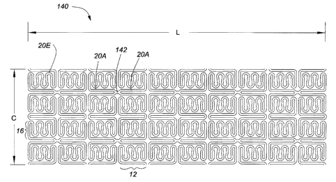
Fig. 16A shows a complete portion of a stent 140 (as laid flat) in accordance
with a prototype
of the present invention which is similar to the stmt portion 100 of Fig. 9
except that the
CA 02358449 2001-07-16
WO 00/42946 PCT/CA00/00035
14
expandable element 16 includes an additional circumferentially-oriented, over-
parallel
functional unit 20E. In addition, adjacent rings 12 are interconnected by a
relatively short
interconnecting member 142 to facilitate axial flexing. As can be seen, the
stmt 140 provides
substantial metal coverage when in its unexpanded state shown in Fig. 16A. The
length L
=15.851mm and the distance C, which is the circumference is 4.393mm which
results in a
tubular stmt of approximately 1.37mm diameter. Fig. 16B illustrates an
enlarged section of
the stmt 140 of Fig. 16A. For reference purposes, Table 2 sets out the length
L and radius R
dimensions (in mm) as measured:
Li LZ L3 La Ls L6 L~ R, Rz R3 Ra Rs R6 R~ Rs
0.8460.5630.3980.070.080.080.080.140.140.090.1650.050.060.1310.05
Table 2
The thickness of the material, i.e the stmt's tubular wall thickness is on the
order of about
0.05-0.2mm.
Fig. 16C shows a portion of the stmt 140 in its expanded form as 140'. The
expandable
elements 16' have started to move diagonally and the axially-oriented
functional units 20A'
have expanded circumferentially to an "under-parallel" disposition. The rings
12' are
prevented from separation by interconnecting members 142'. The expansion
causes a tensile
force component to be exerted along the expandable element 16', causing the
individual
functional units 20E'expand from their originally over-parallel disposition to
parallel as shown
in Fig. 16C and with sufficient expansion, to an under-parallel disposition.
Table 3 sets out the results of radial expansion testing the stent 140.
STENT DIAMETER LENGTH SHORTENING METAL
COVERAGE
(mm) (inches) (mm) (%) (%)
1.37 0.054 16 -- 52
3 0.118 16 0 24
3.5 0.138 16 0 20
4 0.157 16 0 17
Table 3
CA 02358449 2001-07-16
WO 00/42946 PCT/CA00/00035
As can be seen from Table 3, the length of the stmt 140 remains the same over
the range from
its nominal, unexpanded diameter of 1.37mm to 4mm. These results can be
compared with
the results of Uni-Cath, Inc.'s Iris stmt as shown in Table 1, which show stmt
length reduction
as expansion increases. In addition, the stmt 140 retains acceptable metal
coverage over the
5 expansion range.
The self compensating principle as described above with respect to the
diagonally-oriented
functional element 20C of Fig. 3E, can also be combined with the
aforementioned over-
parallel concept for axially- or circumferentially-oriented functional
elements 20D,20E and
arranged to optimize axially flexibility for ease of deployment without
significant detriment
10 to strength of the expanded stmt after deployment. To illustrate the
combination of these
principles, there is shown in Fig. 17 a stmt 150 comprising a plurality of
similar rings 152.
Each ring 152 consists of an alternating series of over-parallel functional
elements 20G which
are arranged diagonally with respect to the longitudinal axis 14 of the stmt
150. Each ring 152
forms a separate oblique cylinder and is not part of a "helical winding", and
accordingly, the
15 end rings 152 are not as prone to splaying as would be the case with a free
end portion of a
helical winding.
As with the stent 50 of Fig. 4B, adjacent rings 152 are interconnected with an
interconnecting
member 154 between opposed bendable joints 156. The interconnecting members
can be
attached in an number of ways, such as for example, bottom-to-bottom as shown,
apex-to-apex
as shown in Fig. 16A, or apex-to-bottom as shown in Fig. 10. Similarly, to
increase the
flexibility as aforesaid, the length of the connecting member 164 between
adjacent rings 162
can be reduced as aforesaid and as illustrated in Fig. 18.
The diagonally-oriented functional unit 20C concept can also be employed in a
stmt without
use of the over-parallel feature of Fig. 3G to substantially the same
advantage. By way of
example, stmt 170 of Fig. 19 is constructed of a plurality of obliquely
disposed rings 172.
Each ring 172 consists of a series of circumferentially expandable elements 16
in this case
connected to the next expandable element in the series by a diagonally-
disposed functional unit
20C. Each expandable element comprises one or more diagonally-oriented
functional units
20C' which in this case are disposed generally at right angles to the
diagonally-disposed
functional unit 20C. Selected apexes of adjacent bendable joints 176 of
adjacent rings 172
may be attached at 174 to form the ring interconnections or the
interconnecting can be
CA 02358449 2001-07-16
WO 00/42946 PCT/CA00/00035
16
accomplished in any of the manners discussed in this application or in
Applicant's
aforementioned International Application No. PCT/CA99/00632.
The stems described herein are preferably fabricated from biocompatible, low
memory, more
plastic than elastic material to permit the stmt to be expanded and deformed,
yet sufficiently
rigid to permit the stmt to retain its expanded and deformed configuration
with an enlarged
diameter and also to resist radial collapse.
Typically, stems in accordance with the teachings herein may be expanded up to
about four
times their original constricted diameters yet still have desirable properties
of good axial
flexibility in the constricted state and resistance to radial collapse and
comprehensive wall
support in the expanded state. Accordingly, stems may be provided for example
in nominal
diameters d of about lmm, l.Smm, and 2mm which, depending on the specific
structure, may
be expanded to 4mm, 6mm or 8mm, respectively, which should enable a minimum
number
of stems to be employed in most situations. It should be borne in mind that
the stems of the
present invention are operable over their entire range because they deform
substantially
continuously under application of an radially outwardly directed force. Upon
removal of the
force, deformation halts and the stmt remains sufficiently rigid to withstand
the radial force
of the wall which it supports.
Suitable materials for the fabrication of the tubular stmt would include
silver, tantalum,
stainless steel (316 L), gold, titanium, NiTi alloy or any suitable plastic
materials such as
thermoplastic polymers. Any medically-suitable metal which is capable of
yielding plastically
under the typical forces of a balloon catheter could also be employed.
Alternatively, the stmt
may be made of a radioactive material or irradiated with a radioactive
isotope. The radioactive
isotope may be a beta particle emitting radioisotope. By using a stmt made of
the radioactive
material, cancer cells in and around the stmt can be deactivated or killed.
Alternatively, the
stmt can be coated with materials that prevent cell overgrowth. The stmt may
be coated with
an anticoagulating medication substance, such as heparin, and/or a
bioabsorbable material.
Accordingly, when the stmt is used in a blood vessel, blood clotting can be
prevented. Also,
the stmt may have pores, indentations or a roughened surface capable of
absorbing or retaining
a drug therein/thereon for slowly releasing the same over time. Thus, when the
stmt with a
drug is implanted in the body lumen, the drug can slowly released in the body
lumen. To
enhance visibility of the stmt when viewed by various different medical
imaging devices, the
end rings can be formed from a radio-opaque material, such as gold, silver or
platinum, which
CA 02358449 2001-07-16
WO 00/42946 PCT/CA00/00035
17
allows both ends of the stmt to be clearly visible through a medical imaging
device during or
after implantation of the stmt within a body lumen of the patient.
The stmt is preferably formed by laser cutting technology wherein the pattern
is cut into a
cylindrical section of the appropriate material. Other suitable methods may be
used, for
example, the stmt can be formed by an etching technique. Namely, a pattern of
the rings and
the interconnecting members are coated on a cylindrical metal member, which is
etched in an
acid solution. Then, un-coated portions are removed.
The thickness of the material, i.e the stmt's tubular wall thickness is on the
order of about
0.05-0.2mm. The cross-sectional configuration of the material can be varied,
although it will
likely depend upon the manner in which the stmt is manufactured. For, example,
using laser
cutting on a piece of tubular material, the resulting members which are
disposed in the
circumferential direction will have roughly rectangular cross-sections while
the members
generally parallel to the longitudinal axis will likely have a slightly
trapezoidal cross-section
if the axis of the laser intersects the axis of the tubular material. A more
rectangular cross-
section would be obtainable with an appropriate offset of the laser's axis.
Having described this invention with regard to specific embodiments, it is to
be understood
that the invention has been described with respect to a limited number of
embodiments. It will
be appreciated that many variations, modifications and other applications of
the invention may
be made. Accordingly, the invention is therefore to be limited only by the
scope of the
appended claims.