Language selection

Search

Patent 2358484 Summary

Third-party information liability

Some of the information on this Web page has been provided by external sources. The Government of Canada is not responsible for the accuracy, reliability or currency of the information supplied by external sources. Users wishing to rely upon this information should consult directly with the source of the information. Content provided by external sources is not subject to official languages, privacy and accessibility requirements.

Claims and Abstract availability

Any discrepancies in the text and image of the Claims and Abstract are due to differing posting times. Text of the Claims and Abstract are posted:

  • At the time the application is open to public inspection;
  • At the time of issue of the patent (grant).
(12) Patent Application: (11) CA 2358484
(54) English Title: TRUCK TRAILER DRAG REDUCER
(54) French Title: REDUCTEUR DE TRAINEE AERODYNAMIQUE POUR ENSEMBLE ROUTIER
Status: Dead
Bibliographic Data
Abstracts

English Abstract


The invention comprises an inflatable bag mounted on each of the rear trailer
doors of a standard tractor-trailer unit. The optimum aerodynamic shape of the
bags with
stable flat external surfaces for air to pass over is created by a series of
internal cords
extending horizontally in a radial array from the medial edge of the base of
each bag to
its corresponding lateral surface, and vertically form the top to the bottom
surfaces of
each bag.


Claims

Note: Claims are shown in the official language in which they were submitted.


Claims:
1. An inflatable drag reducer adapted to be mounted on the rear doors of a
standard
transport trailer, said drag reducer comprising an enclosed bag mounted on
each
of the two trailer doors, said bag having a base surface adjacent to said
trailer
door, said bag having a medial surface adjacent the to medial surface of the
other
of the two said bags, said bag having lateral, upper, and lower surfaces over
which air passes during forward motion of said trawler, said bag containing an
array of internal inelastic cords extending horizontally from the medial edge
of
said base surface to insert into said lateral surface at equally spaced
points, said
bag containing a second array of internal inelastic cards extending vertically
from
said upper surface at equally spaced points to insert into said lower surface
at
equally spaced points, such that upon inflation of said drag reducer the two
said
bags together assume a pyramidal shape with said lateral, upper and lower
surfaces being substantially planar.
2. An inflatable drag reducer as recited in Claim 1 wherein a flexible tubular
member connects the inside of one of said two bags to the inside of the other
of
said two bags, such that when the air pressure in one bag is greater that the
air
pressure in the other bag, then air shall freely pass from the higher pressure
bag to
the lower pressure bag.

5


3. An inflatable drag reducer as recited in Claim 1 wherein said bag has a
zipper in
one of its surfaces, such that under typical operating conditions
approximately
half of the available static head of air pressure is lost through said zipper.
4. An inflatable drag reducer as recited in Claim 1 wherein an elastic cord is
mounted in a circular orientation onto said medial surfaces of each said bag,
such
that when said bags are only partly inflated, said elastic cord draws the bags
medially toward one other.

6

Description

Note: Descriptions are shown in the official language in which they were submitted.


CA 02358484 2001-09-19
Background of the Invention: The invention relates to add-on aerodynamic air
deflectors for the rear surface of a transport trailer. Inflatable drag
reducers have been
described (e. g. McDonald ( 1977) U. S Patent No. 4,006,932, Ryan { 1998) U.
S. Patent
No. 5,823,610), and are more practical than rigid versions (e.g. Lechner
(1994) U.S.
Patent No. 5,375,903, Switlik (1996) U.S. Patent No. 5,498,059, Boivin (2001)
U.S
Patent No. 6,257,654 B 1), because inflatables are light-weight and
collapsible to a very
thin state so as not to interfere with complete trailer door opening which is
important
because there is limited room to maneuver at most loading docks. However,
given that
the standard long-haul trailer in North America is a double door
configuration, this
requires that the drag reducer have two separate halves meeting medially along
a planar
surface when inflated. The external surfaces over which the airstream passes
should also
be planar for minimum turbulence creation and maximum drag reduction.
Inflatables
naturally tend towards a spherical shape without an internal means of
controlling the
position of the surface. The present invention describes a novel configuration
of internal
1

CA 02358484 2001-09-19
cords that allows the two bags to meet neatly along a common. plane, while
having
grossly flat external surfaces that are held firmly in place even in heavy
crosswinds.
To achieve auto-inflation the present invention employs a flexible air-scoop
extending
above the roofline from each bag to capture air pressure from the over-passing
air stream.
Similar such means have been used for inflation purposes in prior art (e.g.
McDonald
(1977) U.S. Patent No. 4,006,932, Needy (1979) U.S. Patent :loo. 4,142,755,
Lechner
(1994) U.S. Patent No. 5,375,903).
To achieve bag stability and avoid surface flailing during inflation and
deflation, an
elastic cord oriented in a circular fashion on the medial surface of each bag
is employed
as disclosed in Andrus (1993) U.S. Patent No. 5,236,347. The present
disclosure further
teaches that the placement of such an elastic cord for a double; bag
configuration is best
on the medial surface of each bag thereby drawing the bags together and away
from
traffic during conditions of partial inflation.
2

CA 02358484 2001-09-19
summary of the Invention: The invention solves the problem of creating an
aerodynamically optimal shape with flat surfaces from a soft inflatable
material, as well
as the problem of the inherent lateral instability of a double bag
configuration. The novel
aspect disclosed herein is a network of internal cords consisting of a
radially oriented
array of horizontal cords that stabilize and flatten the lateral surfaces of
the bags, and a
parallel array of vertical cords that flatten the upper and lower surfaces.
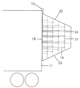
Brief description of the drawings: Figure I is a side view of a trailer with
the invention
mounted. Figure 2 is a face-on view showing the internal cordls. Figure 3 is a
top view
showing the 5 columns of horizontal cords splaying out radially, and the I O
vertical cards
per bag end-on. Figure 4 shows the medial surface of ane half' of the
invention with the
elastic recoil system exposed.
Detailed description of the preferred embodiment: Each h,~lf of the invention
is a
fully enclosed bag 10 mounted permanently onto each of the o-ear doors I I of
the trailer.
A flexible rubber air-scoop I Z feeds air into each bag to provide inflation
pressure with
trailer motion. A circular series of outside patches 13 on the medial side I4
of each bag
I O pauses an elastic cord 15 that functions to draw the bags 1 ~0 together by
contracting
when inflation is only partial, thereby maintaining stability and preventing
lateral flailing
of the bags. An array of horizontal inelastic cards I6 originate from the
medial edge I7
of the base 18 and splay out to insert at equally spaced points on the inner
surface of the
3

CA 02358484 2001-09-19
lateral side 19 and trailing surface 20. There are twenty-seven horizontal
cords 16 per bag
10, twenty-four on the lateral side 19 and three on the trailing surface 20.
An array of
vertical inelastic cords 21 connects the upper surface 22 and lower surface 23
of each bag
10, and intersects with the horizontal cords 16. The horizontal cords 16 and
the vertical
cords 2I are attached to inside patches 24 that are heat sealed to the inside
surface of the
bags 10. A rubber tube 25 that easily disconnects in its middle feeds air from
one bag to
the other in the event of partial air scoop l2 failure or a significant
surface hole in one
bag so as to maintain relatively equal bag pressure and thereby symmetry of
drag reducer
shape. Each bag has a zipper 2~ which can be undane to allow rapid deflation
at the
loading dock. Air leakage through the closed zippers 2fi during operation also
serves to
bleed unnecessary pressure from the bags so that the seams and attachment
points are not
unduly loaded. At 60 mph airspeed, the available static head of air pressure
is about 2.5
inches of water or 0.1 psi. half of which is lost through the closed zippers
2b leaving
about O.OS psi. 'The bag's surface tension will overcome the tension of the
elastic cord 1~
and allow full inflation as iow as 0.025 psi. At 0.05 psi (typical highway
operating
conditions), each of the inelastic cords is loaded with about 7 pounds
tension.
4

Representative Drawing
A single figure which represents the drawing illustrating the invention.
Administrative Status

For a clearer understanding of the status of the application/patent presented on this page, the site Disclaimer , as well as the definitions for Patent , Administrative Status , Maintenance Fee  and Payment History  should be consulted.

Administrative Status

Title Date
Forecasted Issue Date Unavailable
(22) Filed 2001-09-19
(41) Open to Public Inspection 2003-03-19
Dead Application 2006-09-19

Abandonment History

Abandonment Date Reason Reinstatement Date
2005-09-19 FAILURE TO PAY APPLICATION MAINTENANCE FEE

Payment History

Fee Type Anniversary Year Due Date Amount Paid Paid Date
Application Fee $150.00 2001-09-19
Maintenance Fee - Application - New Act 2 2003-09-19 $50.00 2003-09-08
Maintenance Fee - Application - New Act 3 2004-09-20 $50.00 2004-08-09
Owners on Record

Note: Records showing the ownership history in alphabetical order.

Current Owners on Record
ANDRUS, PAUL G.
Past Owners on Record
None
Past Owners that do not appear in the "Owners on Record" listing will appear in other documentation within the application.
Documents

To view selected files, please enter reCAPTCHA code :


To view images, click a link in the Document Description column. To download the documents, select one or more checkboxes in the first column and then click the "Download Selected in PDF format (Zip Archive)" or the "Download Selected as Single PDF" button.

List of published and non-published patent-specific documents on the CPD .

If you have any difficulty accessing content, you can call the Client Service Centre at 1-866-997-1936 or send them an e-mail at CIPO Client Service Centre.


Document
Description 
Date
(yyyy-mm-dd) 
Number of pages   Size of Image (KB) 
Representative Drawing 2002-06-17 1 7
Cover Page 2003-02-21 1 30
Abstract 2001-09-19 1 16
Description 2001-09-19 4 176
Claims 2001-09-19 2 68
Drawings 2001-09-19 4 69
Correspondence 2001-10-19 1 9
Assignment 2001-09-19 2 133
Fees 2003-09-08 1 132
Fees 2004-08-09 1 59