Note: Descriptions are shown in the official language in which they were submitted.
WO 00/40977 CA 02358606 2001-07-06 PCT/US99/30962
REVENUE METER HAVING PRECISION TIME CLOCK
Cross Reference to Related Application
Cross reference is made to United States Patent Application Docket No.
99P7406US, filed January 8, 1999, which is assigned to the assignee of the
present
invention.
Field of the Invention
This invention relates to electricity meters such as used by commercial,
industrial, or residential customers of power utility companies and, more
particularly, to a revenue accuracy meter having various operational
capabilities
such as power quality measurement and/or energy management.
Background of the Invention
Utility power distribution generally starts with generation of the power by
a power generation facility, i.e., power generator or power plant. The power
generator supplies power through step-up subtransmission transformers to
transmission lines. To reduce power transportation losses, the step-up
transformers increase the voltage and reduce the current. The actual
transmission
line voltage conventionally depends on the distance between the
subtransmission
transformers and the users or customers. Distribution substation transformers
reduce the voltage from transmission line level generally to a range of about
2-35
kilo-volts ("kV"). The primary power distribution system delivers power to
WO 00/40977 CA 02358606 2001-07-06
PCT/US99/30962
distribution transformers that reduce the voltage still further, i.e., about
120 V to
600 V .
For background purposes, and future reference herein, an example of a
power utility distribution system as described above and understood by those
skilled in the art is illustrated in FIGS. lA and 1B of the drawings. Power
utility
companies, and suppliers thereto, have developed systems to analyze and manage
power generated and power to be delivered to the transmission lines in the
primary
power distribution system, e.g., primarily through supervisory control and
data
acquisition ("SCADA"). These primary power distribution analyzing systems,
however, are complex, expensive, and fail to adequately analyze power that is
delivered to the industrial, commercial, or residential customer sites through
the
secondary power distribution system.
Also, various systems and methods of metering power which are known to
those skilled in the art are used by commercial, industrial, and residential
customers of power utility companies. These power metering systems, however,
generally only measure the amount of power used by the customer and record the
usage for reading at a later time by the utility power company supplying the
power
to the customer. A revenue accuracy meter is an example of such a metering
system conventionally positioned at a customer site to receive and measure the
amount of power consumed by the customer during predetermined time periods
during a day.
Conventionally, electric power is delivered to industrial, commercial, and
residential customers by local or regional utility companies through the
secondary
WO 00/40977 CA 02358606 2001-07-06
PCT/US99/30962
power distribution system to revenue accuracy type electricity meters as an
alternating current ("AC") voltage that approximates a sine wave over a time
period and normally flows through customer premises as an AC current that also
approximates a sine wave over a time period. The term "alternating waveform"
generally describes any symmetrical waveform, including square, sawtooth,
triangular, and sinusoidal waves, whose polarity varies regularly with time.
The
term "AC" (i.e., alternating current), however, almost always means that the
current is produced from the application of a sinusoidal voltage, i.e., AC
voltage.
In an AC power distribution system, the expected frequency of voltage or
current, e.g., 50 Hertz ("Hz"), 60 Hz, or 400 Hz, is conventionally referred
to as
the "fundamental" frequency, regardless of the actual spectral amplitude peak.
Integer multiples of this fundamental frequency are usually referred to as
harmonic
frequencies, and spectral amplitude peaks at frequencies below the fundamental
are often referred to as "sub-harmonics," regardless of their ratio
relationship to
the fundamental.
Various distribution system and environmental factors, however, can
distort the voltage waveform of the fundamental frequency, i.e., harmonic
distortion, and can further cause spikes, surges, or sags, and other
disturbances
such as transients, time voltage variations, voltage imbalances, voltage
fluctuations and power frequency variations. Such events are often referred to
in
the art and will be referred to herein as power quality disturbances, or
simply
disturbances. Power quality disturbances can greatly affect the quality of
power
received by the power customer at its facility or residence.
WO 00/40977 CA 02358606 2001-07-06 PCT/US99/30962
These revenue accuracy metering systems have been developed to provide
improved techniques for accurately measuring the amount of power used by the
customer so that the customer is charged an appropriate amount and so that the
utility company receives appropriate compensation for the power delivered and
used by the customer. Examples of such metering systems may be seen in U.S.
Pat. No. 5,300,924 by McEachern et al. titled "Harmonic Measuring Instrument
For AC Power Systems With A Time-Based Threshold Means" and U.S. Pat. No.
5,307,009 by McEachern et al. titled "Harmonic-Adjusted Watt-Hour Meter."
These conventional revenue accuracy type metering systems, however,
have failed to provide information about the quality of the power received by
a
power customer at a particular customer site. Power quality information may
include the frequency and duration of power quality disturbances in the power
delivered to the customer site. As utility companies become more and more
deregulated, these companies will likely be competing more aggressively for
power customers, particularly heavy power users, and therefore information
regarding the quality of the power received by the power customer is likely to
be
important.
For example, one competitive advantage that some utility companies may
have over their competitors could be that their customers experience
relatively few
power quality disturbances. Similarly, one company may promote the fact that
it
has fewer times during a month that power surges reach the customer causing
potential computer systems outages at the customer site. Another company may
promote that it has fewer times during a month when the voltage level
delivered to
4
WO 00/40977 CA 02358606 2001-07-06 PCT/U599/30962
the customer is not within predetermined ranges which may be detrimental to
electromagnetic devices such as motors or relays. Previous systems for
measuring
quality of power in general, however, are expensive, are bulky, require
special set
up and are not integrated into or with a revenue accuracy meter. Without a
revenue accuracy metering system that measures the quality of the power
supplied
to and received by the customer, however, comparisons of the quality of power
provided by different suppliers cannot readily be made.
One solution to the above described problems is proposed by U.S. Patent
No. 5,627,759 to Bearden et al. (hereinafter the "Bearden patent"), which is
assigned to the assignee of the present invention and incorporated herein by
reference. The Bearden patent describes a revenue accurate meter that is also
operable to, among other things, detect power quality events, such as a power
surge or sag, and then report the detection of the power quality event to a
utility or
supplier.
One of the useful features of the meter disclosed in the Bearden patent is
waveform capture. The meter of the Bearden patent is operable to obtain
waveform information regarding the voltage and/or current waveform at about
the
time a power quality event is detected. Such a feature is advantageous because
the
captured waveform may be analyzed to help determine potential causes of the
event, the severity of the event, or other pertinent data.
One use of meters that have the waveform capture capabilities of the
Bearden patent is to analyze the waveforms of several such meters after a
power
quality event to determine the performance of a certain portion of the network
at
CA 02358606 2001-07-06
WO 00/40977 PCT/US99/30962
the time of the power quality event. For example, if a power swell occurs over
a
portion of the power distribution system, then the utility may obtain captured
waveforms from various meters on that portion of the network. The utility may
then obtain information on how the power swell propagated through the network,
as well as other information, by comparing the waveforms from the various
meters.
One difficulty of performing analysis on the captured waveforms of several
meters is temporally aligning the captured waveforms. In particular, to
benefit
from comparing the waveforms from several meters after a power quality event,
it
is important to temporally align or synchronize the captured waveforms.
However, commonly used electronic clocks in electronic meters are not highly
synchronized to each other, or in fact, to any external equipment. In the
past,
clock circuits within revenue meters have been calibrated periodically using
the
line voltage signal, which oscillates at 60 Hz. While such a practice
increases the
accuracy of the meter clock circuits, it cannot provide several dispersed
meters
with sufficiently accurate synchronization to produce reliable comparative
waveform analysis.
What is needed, therefore, is a power measurement device which is
coupled with a revenue accurate meter having a mechanism for synchronizing its
internal clock with the clocks of one or more like meters and/or utility
equipment.
Summary of the Invention
The present invention addresses the above needs, as well as others, by
WO 00/40977 CA 02358606 2001-07-06
PCT/US99/30962
providing a source of externally-generated precision time standard information
within a revenue accurate meter. The time standard information, may, for
example, be obtained from a global position satellite (GPS) generated time
standard, a WWV time standard, or an IRIG-type time standard. A meter having
such a source of externally-generated precision time standard information
could
then have its internal clock highly synchronized with other equipment,
regardless
of the location of such equipment.
An exemplary apparatus according to the present invention includes an
electrical energy meter having a voltage digitizing circuit, a current
digitizing
circuit, a metering circuit, a clock circuit, and a source of externally-
generated
time standard information. The voltage digitizing circuit is operable to
obtain
analog line voltage information and generated digital line voltage information
therefrom. Similarly, the current digitizing circuit is operable to obtain
analog line
current information and generate digital line current information therefrom.
The
metering circuit is operable to receive the digital line voltage information
and the
digital line current information and generate metering information therefrom.
The
clock circuit is operable to generate calendar/clock information, said clock
circuit
having a calibration input for receiving precision time calibration
information.
The source of externally-generated time standard information is operably
coupled
to provide precision time calibration information to the calibration input of
the
clock circuit.
The exemplary apparatus described above may further optionally include
waveform capture functionality. Such a device could then capture waveforms and
CA 02358606 2001-07-06
WO 00/40977 PCT/L1S99/30962
associate clock/calendar information with the captured waveform, wherein the
clock/calendar information is calibrated to the externally generated time
standard.
If several such devices are incorporated into a power distribution network,
the
waveforms captured by several such devices would be highly synchronized to
each
other, thereby allowing analysis of the distribution network performance in
the
event of a power quality event.
The above features and advantages, as well as others, will become more
readily apparent to those of ordinary skill in the art by reference to the
following
detailed description and accompanying drawings.
Brief Description of the Drawings
FIGS. IA and 1B schematically illustrate an environmental view of a
revenue accuracy meter having power quality measurement according to the
present invention;
FIGS. 2A and 2B schematically illustrate a revenue accuracy meter having
power quality measurement arranged in communication with a power generator
and a power customer according to the present invention;
FIG. 3 schematically illustrates a revenue accuracy meter having power
quality measurement arranged in communication with various data
communication links according to the present invention;
FIG. 4 illustrates a revenue accuracy meter having power quality
measurement according to the present invention;
FIGS. SA and SB schematically illustrate a flow chart of a digital signal
WO 00/40977 CA 02358606 2001-07-06 PCT/US99l30962
processor circuit of a revenue accuracy meter having power quality measurement
according to the present invention;
FIG. 6 schematically illustrates a power quality measurement circuit of a
revenue accuracy meter according to the present invention;
FIGS. 7A, 7B, and 7C illustrates the operations of a power quality circuit
within the revenue accuracy meter of Fig. 3 in accordance with the present
invention;
FIG. 8 schematically illustrates a revenue accuracy meter having power
quality measurement and energy management according to a second embodiment
of the present invention; and
FIG. 9 schematically illustrates an apparatus for providing control
parameters to the revenue accuracy meter of FIGS. 3 and 4 in accordance with
the
presentinvention.
Detailed Description
The present invention will now be described more fully hereinafter with
reference to the accompanying drawings in which preferred embodiments of the
invention are shown. This invention may, however, be embodied in many
different forms and should not be construed as limited to the illustrated
embodiments set forth herein; rather, these embodiments are provided so that
this
disclosure will be thorough and complete and will fully convey the scope of
the
invention to those skilled in the art. Like numbers refer to like elements
throughout.
WO 00/40977 CA 02358606 2001-07-06 PCT/US99/30962
As illustrated in the schematic environmental view of FIGS. lA and 1B,
utility power distribution 20 generally starts with generation of the power by
a
power generation facility 21, i.e., power generator or power plant. The power
generator 21 supplies power through step-up subtransmission transformers 21 b
to
transmission stations 23. To reduce power transportation losses, the step-up
transformers 21 b increase the voltage and reduce the current. The actual
transmission line voltage conventionally depends on the distance between the
subtransmission transformers 21 b and the users or customers, i.e.,
commercial,
industrial, or residential 37, 38. Distribution substation transformers 25,
26, 27
reduce the voltage from transmission line level generally to a range of about
2-35
kilo-volts ("kV"). The primary power distribution system 31 delivers power to
distribution transformers 28, 28a that reduce the voltage still further, i.e.,
about
120 V to 600 V.
Conventionally, power utility companies and suppliers have developed
systems to analyze and manage power generated and power to be delivered to the
transmission lines in the primary power distribution system 31, e.g.,
primarily
through supervisory control and data acquisition ("SCADA") at a remote
operations center 22 such as illustrated. These operation centers 22 generally
communicate with the generation facilities 21 and the substations 24, 25
through
conventional data communication terminals 21a, 24a, 25a. Because problems
currently arise in the secondary power distribution system 36, i.e., from the
distribution substation to the customers, with respect to analyzing power that
is
l0
WO 00/40977 CA 02358606 2001-07-06 PCT/US99/30962
delivered to the industrial, commercial, or residential customer sites through
the
secondary power distribution system 36, a revenue accuracy meter 40, or a
plurality of revenue accuracy meters 40 is provided having power quality
measurement according to the present invention and preferably is positioned as
illustrated (FIGS. lA-1B) in the secondary power distribution system 36 to
provide a remote terminal or node in the overall system 20 for troubleshooting
or
diagnosing problems, identifying emergency situations, and systematically
analyzing information fram specific customer sites.
Due to the deregulation of the power delivery industry and the consequent
brokering of power at the transmission level, it is also advantageous to
implement
revenue accurate meters 40 having power quality measurement according to the
present invention within the transmission system 31 and/or generation system
21.
FIGS. 2A, 2B, 3, and 4 schematically illustrate a revenue accuracy meter
40 having power quality measurement arranged in communication with a power
generator 80 such as a utility power company and a power customer 60 according
to the present invention. A revenue accuracy meter 40 according to the present
invention is an electricity meter or an alternating current static watt-hour
meter
used for billing functions, i.e., billing meter. These revenue power or
electricity
meters preferably are solid state meters that at least meet American National
Standards Institute ("ANSI") 12.16, International Electrotechnical Commission
("IEC") 687/1036 standard, similar improved or revised standards, or the like,
as
understood by those skilled in the art. As illustrated, the revenue accuracy
meter
40 for measuring the amount and quality of electrical power received by a
power
WO 00/40977 CA 02358606 2001-07-06 PCT/US99/30962
customer 60 preferably has a housing 40a and a communications interface which
preferably includes a plurality of data communication ports 41, 42, 43, 44
positioned in the housing 40a (see FIGS. 3 and 4A). The housing 40a is
configured as is well known in the art to connect the meter 40 to the power
lines
through, for example, a meter socket.
Although four data communication ports 41, 42, 43, 44 are illustrated, a
revenue accuracy meter 40 according to the present invention preferably has at
least two data communications ports. At least one of the plurality of data
communication ports 41, 42, 43, 44 is arranged for data communications with a
power customer 60, e.g., a power customer port 41, and at least one of the
plurality
of data communication ports 41, 42, 43, 44 is arranged for data communications
with a power generator, e.g., power generator ports 42, 43, 44.
The particular embodiment of the ports 41, 42, 43, 44 illustrated, however,
advantageously provides real time data communications with a plurality of the
various groups or departments of a utility company 80 such as marketing 82,
operations 83, engineering 84, and/or billingifinance 85 (FIG. 2B). For
example,
power quality data such as that discussed below in connection with Figs. 6,
7A,
7B, and 7C may be utilized by the customer service or the marketing group 82
receiving data from a revenue accuracy meter 40 according to the present
invention by monitoring power outage, sags/surges, and excessive harmonics.
This information can then be relayed, i.e., by sequential calls, to a head
office, key
account representatives, and/or customers 60. Such power quality data may be
utilized by operations 83 to monitor voltage/current, KWIKVAR, disturbances,
12
WO 00/40977 CA 02358606 2001-07-06
PCT/US99/30962
and/or harmonics received by customers 60 through the meter 40 and to monitor
transformers, i.e., temperature, capacitors, and other control functions in
the power
distribution system 20.
The engineering group or department, for example, may utilize the meter
40 and the data received therefrom for monitoring total harmonic distortion,
for
captured waveform analysis, for spectral analysis, as well as studying and
analyzing outages and sags/surges from a diagnostic approach. The billing or
finance group 85, in turn, may conduct load or rate research based upon
information provided from the meter 40 about power quality and power usage. As
understood by those skilled in the art, the billing group 85 of the power
generator
80, for example, can conduct TOU metering, real-time pricing, transformer
loss,
compensation, load profile, meter installation integrity, meter wiring
verification,
load curtailment, and/or various other functions. Also, these various groups
of the
power generator 80 can also responsively interact with the substation
controller 86
such as in mufti-drop meter applications or to communicate with remote
terminal
units ("RTUs"), printers, or the like. Further, the power generator 80 can
provide
various auxiliary inputs to the meter 40 such as transformer oil temperature
data,
feeder subloads, redundant metering data, status alarms, pressure data, and/or
other information as desired.
The customer, on the other hand, can receive on-line data such as
engineering units, energy cost, subload data, alternate utility data, and
other totals
or specific information as needed. Preferably the meter 40 also has customer
programmed relay control with security, utility alarming, demand prediction,
and
13
CA 02358606 2001-07-06
WO 00/40977 PCT/US99/30962
energy management capabilities. Additionally, as also illustrated in FIGS. 2A
and
8A, a revenue accuracy meter 40 according to the present invention further has
an
energy management controller 90 electrically connected to the second receiver
and
the second transmitter for controlling power usage responsive to predetermined
command signals received from the power customer through the power customer
port of the communications interface. Likewise, the customer may provide
auxiliary inputs 62 to the meter 40 such as alarms, status, production
parameters,
non-electrical utility data, load curtailment data, subload data, as well as
other data
as desired. The meter 40 may also be monitored or utilized by the customer at
a
customer central station 61 as illustrated. The data communication ports also
provide inter or intra-customer communication, i.e., customer to utility or
other
customer and communication within customer facility or locations.
Either separate from the energy management controller 90 or in
conjunction therewith, a meter 40 according to the invention preferably
further has
an access restricter, not shown, coupled in electrical communication with the
power generator port for providing restricted access between the power
customer
port and the power generator port. This security access preferably is resident
in
one of the controllers of the meter 40. This access restriction means or
access
restricter preferably is software programmed as understood by those skilled in
the
art so that access is provided to either the power customer or the power
generator
by a command signal representative of a user password or a data access key.
This,
in turn, provides a wall for security between meter functions used by a
customer
60 and meter functions used by a power generator or other third party 80.
14
WO 00/40977 CA 02358606 2001-07-06
PCT/US99/30962
Although, as understood by those skilled in the art, the communication
interface of a revenue accuracy meter 40 may include any means for
communicating data to and from the meter 40, such as using a probing device,
an
optical device, or a remote device for interfacing with the meter 40, the
communications interface of a revenue accuracy meter 40 preferably includes
one
or more transceivers, e.g., universal asynchronous receiver/transmitter
("UART"),
positioned within the housing 40a of the meter 40 and arranged to receive and
transmit data signals through the data communication ports 41, 42, 43, 44.
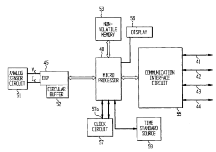
Referring now to Fig. 3 in particular, the exemplary embodiment of the
meter 40 includes an analog sensor circuit 51, a digital signal processing
circuit
45, a circular buffer 52, a microprocessor 48, a non-volatile memory 53, a
time
standard source 54, a communication interface circuit 55, a display 56, a
clock
circuit 57 and the ports 41, 42, 43 and 44.
The analog sensor circuit 51 is a circuit that connects to the utility power
lines and is operable to generate signals including analog line voltage
information
and analog line current information for each of the phases in a polyphase
power
system. In the exemplary embodiment described herein, the analog sensor
circuit
51 is operable to obtain analog line voltage information, VA, VB and VC, and
analog line current information, IA, IB and IC for three phases of a three
phase
electrical system. To this end, the analog sensor circuit may suitably include
voltage divider circuits, current shunts, current transformers, embedded
coils,
and/or other well known voltage and current multiple outputs sensing
technology.
The digital signal processing ("DSP") circuit 45 and the microprocessor 48
CA 02358606 2001-07-06
WO 00/40977 PCT/US99/30962
together comprise a metering circuit that is operable to receive line voltage
and
line current information from the analog sensor circuit 51 and generate
metering
information therefrom. In particular, the DSP circuit 45, in addition to a
DSP,
includes one or more analog to digital signal converters that receive the
analog
line voltage information and analog line current information and generate
digital
line voltage information and digital line current information therefrom. The
DSP
circuit 45 and microprocessor 48 are furthermore suitably programmed to
receive
the digital line current information and digital line voltage information from
the
analog to digital converters and generate metering information therefrom. The
metering information includes watts, VAR and VA quantities representative of
energy consumed by the customer. Further detail regarding the operation of the
metering circuit is described below in connection with FIGS. SA and SB.
The DSP circuit 45 and the microprocessor 48 also together comprise a
power quality circuit operable to capture waveforms in accordance with the
present invention. Further detail regarding the operation of the power quality
circuit is described below in connection with FIGs. 6, 7A, 7B, and 7C.
It will be noted that the architecture of the metering circuit and power
quality circuit describe above is given by way of example only. Those of
ordinary
skill in the art may readily devise alternative architectures that incorporate
the
principles of the metering circuit and power quality circuit described herein.
For
example, the use of a combination of a DSP circuit and a microprocessor as the
metering circuit and power quality circuit is given by way of example only. A
single processor may suitably be used for either or both of such circuits.
Such a
16
WO 00/40977 CA 02358606 2001-07-06 PCT/US99/30962
single processor may require relatively high processing speeds to accomplish
revenue quality metering and therefore may not be as cost effective as the
architecture discussed herein. Alternatively, those of ordinary skill in the
art may
employ metering circuits and/or power quality circuits according to the
present
invention that incorporate three or more processors, or that incorporate
different
types of controllers and processors. Such architectures would provide at least
some of the advantages of the present invention.
The power quality circuit of the meter 40 further includes the circular
buffer 52. The circular buffer 52 is a circuitous memory structure within at
least a
portion of a memory device, preferably RAM. The circuitous memory structure
stores digital line voltage and/or digital line current values in the sequence
in
which they are received. Once the circular buffer 52 is full, each new value
entered replaces the oldest value in the buffer. In the present invention, the
circular buffer 52 may suitably be an allocated portion of the internal RAM of
the
DSP circuit 45. However, the circular buffer 52 may alternatively comprise an
external RAM or even RAM that is internally or externally coupled to the
microprocessor 48.
Returning to the exemplary embodiment of the meter 40 illustrated in Fig.
3, the non-volatile memory 53 may suitably be a flash memory non-volatile RAM,
EEPROM, or other non-volatile memory. Non-volatile RAM and flash memory
are preferable because the footprint of such memories per unit of memory is
significantly smaller than the footprint of EEPROM. However, EEPROM can be
advantageous when battery back-up or other back up power sources are
17
WO 00/40977 CA 02358606 2001-07-06 PCT/US99/30962
impractical or unreliable. Preferably, the non-volatile memory 53 has 4 to 8
megabytes of memory.
The time standard source 54 is a source of externally-generated precision
time standard information. For example, the time standard source 54 may
suitably
be a GPS receiver operable to obtain precision time standard information via
satellite. Alternatively, the time standard source may be an IRIG or WWV time
standard receiver. An example of a time standard source that may be
incorporated
into the meter 40 is the model GPS-PCI card available from TrueTime, Inc.
The clock circuit 57 is a circuit well-known in the art that is operable to
generate clock/calendar information in an ongoing manner. In general, the
clock
circuit 57 may suitably include a crystal oscillator circuit and appropriate
logic
gates and counters for generating clock/calendar information based on the
crystal
oscillator circuit. Such circuits are well known. The clock circuit 57 is
coupled to
the microprocessor to provide the clock/calendar information thereto. The
clock
circuit 57 also has a calibration input 57a that is operably connected,
through the
microprocessor 48, to receive the externally generated precision time
information
from the time standard source 54. The clock circuit 57 is operable to adjust
its
clocklcalendar information based on the received externally generated
precision
time information. In accordance with the exemplary embodiment described
herein, the time standard source 54 provides precision time information in the
form of pulse, i.e. one pulse per second. Thus, the clock circuit 67 is
"recalibrated" each time it receives a pulse.
It will be noted that in some clock circuits, the calibration input may
1s
WO 00/40977 CA 02358606 2001-07-06
PCT/US99/30962
suitably be the connection through which clock/calendar information is
provided
to the microprocessor 48. Moreover, it will be understood that the clock
circuit 57
may be integrally formed with the microprocessor 48.
The display 56 is an LCD or other display circuit operable to display data
provided by the microprocessor 48. The display 56 and/or the microprocessor 48
includes any necessary drivers for converting the microprocessor data into
signals
that cause the LCD or other display medium to display the information
contained
in the data. Such circuits are well known.
The communication interface circuit 55 cooperates with the
communication ports 41, 42, 43, and 44 to effectuate communication between the
meter 40, through the microprocessor 48, and external devices, including
remotely
located external devices. To this end, the communication interface circuit 55
may
include one or more additional processors that assist in providing such
communications.
The ports 41, 42, 43 and 44 preferably include an RS-232 interface port
and/or a 20 milliampere ("mA") current loop, an optical port, and two of
either an
internal modem, a direct interface, a protocol converter, or an RS-485 port.
The
internal modem is arranged for communicating with utility customer or power
customer auxiliary inputs and outputs. The direct interface ("I/F") is
arranged to
connect to an external modem which may provide either additional or
duplicative
data to the processors 45, 48. The protocol converter and the RS-485 port are
likewise arranged to provide data communication to the operations center 22
(see
FIG. 1) as well as the local area network ("LAN") of the utility company or
19
WO 00/40977 CA 02358606 2001-07-06 PCT/US99/30962
industrial consumer. The optical port preferably is arranged for data
communication through a power generator port to laptop computers or the like.
The current loop provides secure data communication and, preferably, is
arranged
for data communication with the auxiliary inputs 81, 85 from the utility 80,
such
as an encoder, printer, RTU, various software or hardware tools, personal
computer, remote data display, or the like. The external modem and the LAN are
connected in electrical communication with the desired group 82, 83, 84, 86 of
the
utility or power generator 80 as illustrated.
The elements of the meter 40 described above of FIG. 3 are
advantageously configured to reside within a single housing that is operable
to be
mounted on select ones of standard meter sockets, as illustrated in Fig. 4.
FIGS. SA and SB show in further detail the operation of the metering
circuit and the power quality circuit of the meter 40 of FIG. 3. In
particular, the
DSP circuit 45 portion of the metering circuit and power quality circuit is
shown
in detail in FIGs. SA and SB. In general, the DSP circuit 45 receives the
analog
line voltage information and analog line current information and performs the
preliminary metering calculations as well as preliminary power quality
determinations as described herebelow. With respect to metering calculations,
the
DSP circuit 45 samples and processes the analog line voltage and current
signals
using high computational speeds and generates interim values such as
accumulated watts, VA, and VAR values. By way of example, the DSP circuit 45
samples each line voltage and line current signal 32 times per second. This
sampling rate, combined with the use of 20 bit resolution samples, allows the
WO 00!40977 CA 02358606 2001-07-06 PCT/US99/30962
meter 40 to perform revenue accurate metering measurements.
The microprocessor 48 periodically retrieves the accumulated interim
values and uses them to generate standard meter energy pulses. The
microprocessor 48 also accumulates various energy consumption values in
compliance with metering standards. The microprocessor 48 further operates to
cause display of certain metering values and/or communication of metering
values
to the consumer or the utility.
The DSP circuit 45 further employs the sampled or digitized line voltage
signals, and in some cases the digitized line current samples, to determine
the
presence of undesired variations in the electrical signal representative of
power
received by a power customer 60 across electrical power lines or the like such
as
spikes, surges, sags, harmonic distortion, and/or other disturbances. The
variation
determining means preferably is a variation determiner, or other power quality
circuit 200, as illustrated coupled in electrical communication with the
receiver for
determining frequency, i.e., time periods or time occurrences, and duration of
undesired variations in the received voltage signal during a plurality of
predetermined time periods. These undesired signal variations are preferably
minimum or maximum threshold variations and/or timing frequency variations of
the supplied signal. The operation of the power quality circuit is discussed
in
further detail in connection with FIG. 6.
Once an undesired signal variation is detected, information is passed to the
microprocessor 48 which controls the communication and/or storage of
information regarding the variation, including waveform capture in accordance
21
CA 02358606 2001-07-06
WO 00/40977 PCT/US99/30962
with the present invention, as described below in connection with FIGS. 7A, 7B
and 7C.
As best illustrated in FIGS. SA and SB, the DSP circuit 45 receives analog
line voltage information VX and analog line current information IX which is
representative of the power received by a power customer on one phase of a
polyphase system. In a three phase system, the DSP circuit 45 receives the
line
current information and line voltage information of each phase in sequential
manner. To this end, the analog line current and analog line voltage
information is
multiplexed so that only one line voltage VX and only one line current IX is
received at any particular instant. It will be noted that in the alternative,
the circuit
shown in FIG. SA may suitably be duplicated for each of the phases of the
system.
In any event, the sample and digitize circuit 111, which is preferably an
A/D converter, converts IA to a digital line current signal. Likewise, the
sample
and digitize circuit 101, which is also preferably an A/D converter, converts
VA to
a digital line voltage signal. Time compensators 102, 112 then compensate for
time skew in sampling due to multiplexing a single analog-to-digital
converter.
The time compensators 102, 112 may suitably be short FIR or smoothing filters
with non-symmetrical coefficients to get the proper time skew with a
reasonably
flat frequency response.
Alternatively, time compensators 102, 112 may be omitted if
simultaneously sampling A/D converters are used. In such a case, measurement
alignment is achieved through synchronization of the A/D converters.
In any event, the compensated digital signals then are respectively received
22
WO 00/40977 CA 02358606 2001-07-06 PCT/US99/30962
by low pass filters 103, 113. The digital line current signal passes through a
fixed
high pass filter 114 and the digital line voltage signal passes through an
adjustable
high pass filter 104. A calibration factor 115, 135 is then respectively
applied to
the filtered signals. After calibration, the digital line current signal and
the digital
line voltage signal is applied to the power quality circuit 200 of the meter
40
according to the present invention. As understood by those skilled in the art,
the
power quality circuit 200 preferably is in the form of software andlor
hardware
resident within or in electrical communication with the DSP circuit 45 and the
microprocessor 48 of the present invention. Figs. 6, 7A, 7B, and 7C illustrate
the
operations of the power quality circuit 200 in further detail.
Once the power quality circuit 200 receives the digital line current and
digital line voltage information, the meter calculations are then preferably
continued by initiating the start customer load detectors 125, 145. As
understood
by those skilled in the metering art, these detectors 125, 145 preferably
assure that
relatively very small signals, i.e., due to leakage current, register as zero
usage.
The signal then passes through delay adjustments 126, 146 to lower the
sampling
rate, e.g., through decimation. The delay adjustments preferably allow the
normal
power measurement process to run at a slower rate and therefore use less of
the
resources of the microprocessor 48 or DSP circuit 45. The signal passes to a
system configuration block 147 to allow for special meter types such as a 2-
1/2
wye meter.
As illustrated in FIG. 5B, the signal further passes through a filtering
configuration 162 preferably such as illustrated. The current signal
preferably is
23
WO 00/40977 CA 02358606 2001-07-06 PCT/US99/30962
applied to a low pass filter 103A. This filter 103A produces a phase shift
that
approaches 90 degrees lag as the frequency of the amplitude signal increases.
This
filter 103A also produces an amplitude response that decreases with frequency,
which is compensated by the two FIR filters 103B and 104A as illustrated. The
output of the voltage FIR filter 104A is then applied to a low pass filter
104B.
Because the VAR measurement preferably may require a 90 degree lag of voltage
relative to current, as understood by those skilled in the art, and the
current is
lagged by 90 degrees already, an additional lag of 180 degrees is needed in
the
voltage. A signal inversion by an inverter 104D preferably supplies this lag.
The
output of multiplier 129 thus provides VARs with errors due to 103A only
approaching 90 degrees. Multiplier 128 produces an error correction signal of
the
correct level and phase to correct the errors when summed in summer block 148.
The scalers 103C, 104C, and 104E preferably adjust signal levels so that
watts and VARs have the same scale factors in the system 162. The outputs of
multipliers 151, 154, 161, and 192 are therefore amperes squared, watts, volts
squared, and neutral amps squared as measured by conventional metering.
Multipliers 172, 175 and 182 preferably have their input 60 Hertz fundamental
removed by filters 171 and 181 so that their outputs are the harmonic amperes
squared, harmonic watts, and harmonic volts squared. As illustrated by FIG.
SB,
multiplier 192 also has as its input the output of a 3-phase current summer
191.
These values or quantities are then integrated in accumulators 152, 155, 163,
165,
173, 176, 183, 193, 197 and copied into buffers 153, 156, 164, 166, 174, 177,
184,
194, 198. In addition, the harmonic amperes for the three phases are summed
and
24
WO 00/40977 CA 02358606 2001-07-06 PCT/US99/30962
multiplied (Blocks 195, 196) to generate harmonic neutral current squared. The
original signal prior to the filter is also checked at block 158. The zero
cross signal
from block 158 causes the accumulator copies 153, 156, 164, 166, 174, 177,
184,
194, 198 to have an integer number of cycles such as for stable short term
readings.
The microprocessor 48 then periodically retrieves the values from the
buffers 153, 156, 164, 166, 174, 177, 184, 194 and 198 and generates the
metering
quantities therefrom . In particular, the microprocessor 48 accumulates watts,
VAs, VARs and performs other energy-related calculations known in the art.
Once the values have been retrieved from the buffers, the buffers 153, 156,
164,
166, 174, 177, 184, 194, and 198 are cleared.
FIG. 6 illustrates a power quality circuit 200 of the invention illustrated in
the form of a variation determiner. The power quality circuit 200 at its input
receives per phase digital line voltage information (andlor digital line
current
information) in the form of digital samples. It will be noted that the power
quality
circuit 200 segregates
each phase such that each of the below operations is performed individually
for
each phase.
The digital samples are provided to both the circular buffer 52 and the
scaler 210 of the variation determiner. In particular, each digital line
voltage
sample is provided to the circular buffer 52 prior to further processing
within the
variation determiner. The circular buffer 52 stores the most recent NN
samples,
WO 00/40977 CA 02358606 2001-07-06 PCT/US99/30962
where NN is a predetermined number, typically defined by an operator and
programmed into the meter. Further detail regarding the programming of values
into the meter 40 is discussed below in connection with FIG. 9. The circular
buffer 52 therefore, at any time, contains digital line voltage information
representative of the line voltage waveform for the most recent MM cycles,
where
MM = NNl(samples per cycle).
In an alternative embodiment, a data compression function may be
introduced at the input of the circular buffer 52. The data compression
function
could be any suitable data compression algorithm and would reduce the amount
of
samples required to represent the waveform shape. The use of such a data
compression function would thereby conserve memory space, albeit at the cost
of
processing power.
In any event, the scaler 210, which also receives the digital line voltage
information, provides the scaled digital line voltage signal to a summation
device
111. The scaler 210 preferably scales the size of the signal to assure against
math
overflows. The scaler 210 also preferably squares the signal so as to make the
meter responsive to root mean square ("RMS") voltage. The scaled signal is
then
summed at the summation device 211. A voltage cycle time determiner 212 is
coupled in electrical communication with the scaler and/or squarer 210, i.e.,
through the summation device 21 l, for determining voltage cycle time. Half
cycle
timing 213 and waiting 214 periods are preferably for synchronizing or zeroing
the
sum 215 of the timing of the system 200. Accumulation preferably occurs for
one-half cycle, passes the result to an FIR filter 216, then clears the
accumulator,
26
WO 00/40977 CA 02358606 2001-07-06 PCT/US99/30962
i.e., S =0.
The multiple tap FIR filter 216, i.e., preferably includes 1-6 taps, and is
coupled in electrical communication with the cycle time determiner 212 for
smoothing and/or filtering the voltage squared signal. The number 216a and the
coefficients 216b for the taps are input into the FIR signal smoothing device
216.
It will also be understood that the electrical signals as illustrated in FIGS.
6-7C of
the power quality circuit 200 are illustrative for the voltage signals, but
under
appropriate current signal characterization parameters may also include the
current
signals.
The output of the FIR signal smoothing device 216 is then provided to a
voltage handler 230. The voltage handler 230 is the block that compares the
resultant value with expected values to determine if a line voltage variation
is
present. More importantly, the voltage handler 230 determines whether a
detected
line voltage variation exceeds one or more variation thresholds and causes
waveform capture in accordance with the present invention. In addition, once
such a variation is detected, the voltage handler 230 subsequently determines
when the variation reduces to a point where it no longer exceeds one or more
thresholds and causes further waveform capture in accordance with the present
invention. To this end, the voltage handler 230 in the exemplary embodiment
described herein operates as described below in connection with FIGS. 7A, 7B,
and 7C.
The flow diagram illustrated in FIGS. 7A, 7B, and 7C illustrate the steps of
the variation detection and waveform capture operations of the exemplary
27
WO 00140977 CA 02358606 2001-07-06 PCT/US99/30962
embodiment of the present invention. It is noted that the most of the
operation of
the voltage handler 230 as illustrated in FIGS. 7A, 7B, and 7C is preferably
carried
out in the DSP circuit 45, which is designed to readily handle calculations at
the
sample rate required for the revenue accurate metering circuit operation.
However, because the operations of the voltage handler 230 in the present
embodiment require the voltage measure for an entire half cycle, the
operations are
suitably slow enough to be carried out by the microprocessor 48 if desired. In
some cases, it may be preferable to have a combination of the DSP circuit 45
and
the microprocessor 48 carry out the operations of the voltage handler 230.
In any event, referring to FIG. 7A, the voltage handler 230 first receives
the voltage magnitude information, represented herein as the value VOLT, from
the FIR smoothing circuit 216 (step 305). The voltage handler 230 then
determines whether the variation of VOLT from an expected value exceeds a
first
variation threshold (step 310). If so, then the voltage handler 230 proceeds
to step
320. If not, however, then the voltage handler 230 proceeds to step 315.
In particular, in step 310, the voltage handler 230 compares VOLT to a set
point level, which may be a high set point level or a low set point level. The
high
set point level represents a voltage magnitude level (in the same units as
VOLT)
above which a potential waveform capture event is identified. Typically, the
high
set point level corresponds to a voltage level that, if maintained for several
half
cycles, indicates a power quality event. Likewise, a low set point level
represents
a voltage magnitude level below which a potential waveform capture event (i.e.
power quality event) is identified. Thus, for example, if the nominal or
expected
28
CA 02358606 2001-07-06
WO 00/40977 PCT/US99/30962
line voltage level is 120 volts, then a low set point level may be set to
correspond
to a detected line voltage of 90 volts. Set point levels may either be preset
or
programmed into the meter 40 by the programming device 600 discussed below in
connection with FIG. 9.
In the preferred embodiment discussed herein, the programming device
600 may be used to set multiple points both for high set points and low set
points.
The second set point may suitably identify a sub-event within a power quality
event, such as a further voltage sag, that occurs within a power quality event
identified by the first set point. Accordingly, it can be seen that several
layers of
set points, both below the expected line voltage level and above the expected
line
voltage level may be employed.
In any event, if the variation of VOLT exceeds the first variation threshold
(or in other words, VOLT is greater than a first high set point or less than a
first
low set point), then an index of consecutive variations N is incremented (step
320). If, however, the variation of VOLT does not exceed the first variation
threshold, then the index N is reset to zero (step 315) and the voltage
handler 230
returns to step 305 and proceeds accordingly with the next value received from
the
FIR smoothing filter 216.
Referring again to step 320, after the index N is incremented, the voltage
handler 230 determines whether N exceeds a predetermined variation duration
value (step 325). The variation duration value represents a minimum number of
half cycles that the variation of VOLT must exceed the first variation
threshold to
trigger the waveform capture. The predetermined value is set such that a
spurious
29
WO 00/40977 CA 02358606 2001-07-06 pCT/US99/30962
transient that is insignificant from a power quality standpoint will not
trigger a
waveform capture and other power quality event recording and reporting
functions. To this end, the predetermined valve may be 2, 4, or 6 half cycles.
The
predetermined value may suitably be set by an operator.
It will be noted that other techniques for distinguishing between spurious
variations and real power quality events may be used. For example, FIGS. 7A,
7B, and 7C of U.S. Patent No. 5,627,759 illustrate in further detail such a
technique that may be incorporated into the meter 40 described herein.
In any event, if the voltage handler 230 determines that N does not exceed
the predetermined variation duration value, then the voltage handler returns
to step
305 to receive the next voltage magnitude value and proceed accordingly.
If, however, N exceeds the predetermined variation duration value, then the
voltage handler resets N (step 330) and records the time and date of the power
quality event (step 335). In particular, the time and date information
provided by
the clock circuit 57 is written immediately to a buffer signifying the
detection of a
waveform capture event.
The voltage handler 230 also retrieves the circular buffer contents. The
circular buffer contents include the previous MM cycles worth of historical
waveform sample data. The voltage handler 230 then forms a power quality event
record. The power quality event record may suitably be a time value series
data
structure that includes the circular buffer contents and the time and date
information.
The voltage handler 230 then writes the record to a memory and/or
CA 02358606 2001-07-06
WO 00/40977 PCT/US99/30962
communicates the record to the utility customer or the utility generator or
supplier
(step 345). In particular, the voltage handler 230 may cause the record to be
stored
in either a memory that is inherent to either the DSP circuit 45 or the
microprocessor 48, or an external memory, not shown. Such a memory may
suitably be a random access memory or a sequentially accessed memory.
However, it is preferable that at least some power quality event records be
written
to the non-volatile memory in order to preserve the data upon loss of power to
the
meter.
Thus, each time the line voltage magnitude exceeds the first variation
threshold for N half cycles, the buffer contents are recorded, or in other
word, the
line voltage (or line current) waveform is captured, by generation of the
power
quality event data record.
It is noted that it is also preferable to obtain data representative of
several
waveform cycles that occur after the power quality event is first detected in
step
335. To this end, the voltage handler 230 may execute a subprocess in which
the
requisite number of additional line voltage samples are provided to the power
quality event data record. The number of line voltage samples to be recorded
after
detection of a variation that exceeds the first variation threshold also is
programmed into the meter 40 by an operator.
It will thus be noted that the waveform that is captured after detection of
the variation exceeding the first variation threshold may consist of: digital
line
voltage information corresponding to a predetermined amount of time before and
up to the detection; digital line voltage information corresponding to the
time of
31
CA 02358606 2001-07-06
WO 00/40977 PCT/US99/30962
the detection to a predetermined amount of time after the detection; or
digital line
voltage information corresponding to a predetermined time before to a
predetermined time after the detection. In this manner, the waveform
information
directly surrounding the time a power quality event occurs is captured for
subsequent analysis.
The use of a precision time standard clock provides a further advantage of
allowing several meters having the capability of the meter 40 to record power
quality event data having time stamps that are completely synchronized. For
example, if a power quality event occurs and is detected by four meters in a
several mile radius, then the waveforms captured at those four meters may be
analyzed to determined how the power quality event affected the power network.
Because each of the four meters employs a precision time standard clock, the
captured waveform data from each meter can be corresponded exactly to
waveforms from the other meters. Such information allows analysis of how a
particular problem propagated through the network as well as other valuable
power network analysis information.
In any event, after step 345, the voltage handler proceeds to step 350 of
FIG. 7B. The portion of the flow diagram in FIGS. 7B and 7C illustrate an
example of how end-of event and sub-event waveform capture according to the
present invention may be carried out. It is noted that when the voltage
handler 230
executes step 350, the meter 40 has already detected and indeed is currently
within
a power quality event as defined by the first variation threshold.
At step 350, the voltage handler 230 again awaits and receives the voltage
32
WO 00/40977 CA 02358606 2001-07-06 PCT/US99/30962
magnitude information, VOLT, from the FIR smoothing circuit 216. The voltage
handler 230 then determines whether the variation of VOLT from an expected
value is less than the first variation threshold (step 355). If so, then the
voltage
handler 230 proceeds to step 365. If not, however, then the voltage handler
230
proceeds to step 360. If the variation is less than the first variation
threshold, then
it may indicate that the present power quality event is ending and the line
voltage
is returning to within normal parameters.
Specifically, if the variation is less than the first variation threshold,
then a
second variation duration index L is reset to zero (step 360). The second
variation
duration index L is discussed in further detail below in connection with steps
410
to 420. The voltage handler 230 then increments the variation reduction
duration
index M (step 370). The voltage handler 230 then determines whether the index
M is less than a predetermined variation reduction duration value. In
particular,
similar to the detection of the first variation in steps 310 to 325, the
voltage
handler 230 only records a reduction in the variation of the line voltage from
the
first variation threshold if there are a predetermined number of half cycles
in
which the variation is below the first variation threshold.
If M does not exceed the variation reduction duration value, then the
voltage handler 230 returns to step 350 to await further line voltage
information.
If, however, M exceeds the variation reduction duration value, then the
voltage
handler 230 performs the waveform capture operations described below in
connection with steps 380 through 395. Accordingly, the meter 40 of the
present
invention performs waveform capture not only at the beginning of a power
quality
33
CA 02358606 2001-07-06
WO 00/40977 PCT/US99/30962
event, such as that detected in the operation of steps 330 through 345, but
also at
the end of a power quality event. To this end, the meter 40 performs waveform
capture both when a variation of the line voltage exceeds a variation
threshold and
when the variation of the line voltage is reduced below the variation
threshold.
In step 380, the voltage handler 230 resets M. The voltage handler 230
then records the time and date of the power quality event (step 385). In
particular,
the time and date information provided by the clock circuit 57 is written
immediately to a buffer signifying the detection of a waveform capture event.
The voltage handler 230 also retrieves the circular buffer contents (step
390). In particular, as discussed above, the circular buffer contents include
the
previous MM cycles worth of waveform sample data. The voltage handler 230
generates a power quality event record comprising the circular buffer contents
and
the time and date information.
The voltage handler 230 then writes the record to a memory and/or
communicates the record to the utility customer or the utility generator or
supplier
(step 395). As discussed above, it is often preferable to obtain several
cycles of
waveform sample data after the power quality event is identified in step 335.
To
this end, the voltage handler 230 may execute a subprocess in which the
requisite
number of additional line voltage samples are provided to the power quality
event
data record.
After step 395, the voltage handler 230 has determined that the line voltage
magnitude has returned to within normal parameters. The voltage handler 230
than returns to step 305 of Fig. 7A and proceeds accordingly. Referring again
to
34
WO 00/40977 CA 02358606 2001-07-06
PCT/US99/30962
step 355, if it is determined that the variation of the present measure of
VOLT is
not below the first variation threshold, then the voltage handler 230 executes
a
sequence of operations that determine whether the variation of VOLT exceeds a
second variation threshold, which could indicate a sub-event within the
presently
detected power quality event.
In particular, if in step 355 it is determined that the variation of VOLT is
not below the first variation threshold, then the variation reduction duration
index
Mis reset to zero (step 360). The voltage handler 230 then determines whether
the variation of VOLT from a value representative of the expected line voltage
exceeds the second variation threshold (step 405).
In particular, the second variation threshold corresponds to a second
predetermined set point level that is in the same direction as the first set
point
level. In other words, if the first variation threshold that was exceeded was
a
variation of the line voltage below the expected voltage level, then the
second
variation threshold is a variation of the line voltage further below the
expected
voltage level. Conversely, if the first variation threshold that was exceeded
was a
variation of the line voltage above the expected voltage level, then the
second
variation is a variation of the line voltage further above the expected line
voltage
level.
If the variation is not greater than the second variation threshold, then the
second variation duration counter L is reset to zero (step 415) and the
voltage
handler 230 returns to await further values of VOLT at step 350.
If, however, the variation is greater than the second variation threshold,
WO 00140977 CA 02358606 2001-07-06 PCT/US99/30962
then the voltage handler 230 increments the second variation duration index L
(step 410). After the counter L is incremented, the voltage handler 230
determines
whether L exceeds a predetermined second variation duration value (step 420).
The second variation duration value represents a minimum number of half cycles
that the variation of VOLT must exceed the second variation threshold to
trigger
the waveform capture, which provides similar protections from spurious voltage
anomalies as those discussed above in connection with step 325.
If the voltage handler 230 determines that L does not exceed the
predetermined second variation duration value, then the voltage handler
returns to
step 350 to receive the next voltage magnitude value and proceed accordingly.
If, however, L exceeds the second variation duration value, then the
voltage handler resets L (step 425) and obtains the time and date information
corresponding to the detection (step 430). The voltage handler 230 also
retrieves
the circular buffer contents (step 435). The voltage handler 230 then
generates a
power quality event record comprising the circular buffer contents, the time
and
date information, and a predetermined number of post detection line voltage
samples. The voltage handler 230 then writes the record to a memory andlor
communicates the record to the utility customer or the utility generator or
supplier
(step 440).
Thus, once power quality event has been detected in steps 305 to 325, the
meter 40 of the present invention monitors for a second level of variation of
the
line voltage (or line current) from an expected value. Such a second level of
variation may be preprogrammed as a second set point into the meter 40 by an
36
CA 02358606 2001-07-06
WO 00/40977 PCT/US99/30962
operator as discussed below in connection with FIG. 9. As discussed above, the
meter 40 then captures the waveform of the line voltage at the time
surrounding
the detection of the second level of variation. Such information provides
further,
in depth information relating to a power quality event. Power providers,
generators, and consumers may use such information to learn about how and why
the event occurred, and what effect it may have had on the power consumer's
equipment.
An exemplary use of the captured waveform data for two or more such
nested levels of variation within a disturbance event is to plot the data in
order to
measure customer equipment response to the disturbance as compared to standard
power quality tolerance curves. One such power quality disturbance curve is
the
Computer Business Equipment Manufacturing Association (CBEMA) curve,
which is provided in LE.E.E. standard 446.
Once the second variation power quality event record has been generated
and stored and/or communicated in step 440, the voltage handler 230 then
monitors the line voltage to detect when the variation is reduced to less than
the
second variation threshold (or first variation threshold). To this end, the
voltage
handler 230 executes the flow diagram illustrated in FIG. 7C, beginning with
step
445. It is noted that in accordance with the flow diagram illustrated in FIG.
7C,
the voltage handler 230 will cause waveform capture if the variation of VOLT
falls below the second variation threshold and not the first variation
threshold for a
predetermined number of half cycles. However, the voltage handler 230 also
monitors whether the variation of VOLT from the expected value falls below the
37
CA 02358606 2001-07-06
WO 00/40977 PCT/US99/30962
first variation threshold.
In step 445, the voltage handler 230 receives a voltage magnitude
information value, VOLT, from the FIR smoothing circuit 216. The voltage
handler 230 then determines whether the variation of VOLT from an expected
value is less than the second variation threshold (step 450). If so, then the
voltage
handler 230 proceeds to step 455. If not, however, then the voltage handler
230
proceeds to step 460. In step 460, an index J, which represents the number of
consecutive values of VOLT that varied from the expected value in an amount
less
than the second variation threshold, is reset to zero. After step 460, the
voltage
handler returns to step 445 to await the next value of VOLT.
In step 455, which is executed when the variation of VOLT does fall below
the second variation threshold, the index J is incremented.
The voltage handler 230 then determines whether the variation of VOLT
from an expected value is less than the first variation threshold (step 465).
If so,
then the voltage handler 230 increments the counter M (step 470) and then
proceeds to step 480. If not, however, then the voltage handler 230 resets the
value of M (step 475) and then proceeds to step 480. Steps 465 through 475
begin
accumulation of the index M in the event that the line voltage returns to a
value
that is less than the first variation threshold before the value of J reaches
the
second variation reduction duration value. In other words, before the value of
J is
sufficient to signify that the sub-event represented by the second variation
threshold is over, the line voltage may have returned to within its normal
parameters. In such a case, the steps 465 through 475 begin incrementing the
38
CA 02358606 2001-07-06
WO 00/40977 PCT/US99/30962
counter Mfor use when the voltage handler 230 returns to the flow diagram in
FIG. 7B, as discussed further below.
The voltage handler 230 then determines whether J exceeds the second
variation reduction duration value (step 480). In particular, similar to the
detection of the first variation in steps 310 to 325, the voltage handler 230
only
records a reduction in the variation of the line voltage from the second
variation
threshold if there are a predetermined number of half cycles in which the
variation
is below the second variation threshold.
If J does not exceed the second variation reduction duration value, then the
voltage handler 230 returns to step 445 to await further line voltage
information.
If, however, M exceeds the second variation reduction duration value, then the
voltage handler 230 performs the waveform capture operations described below
in
connection with steps 485 through 500. Accordingly, the meter 40 of the
present
invention performs waveform capture not only at the beginning and end of a
power quality event, such as described above in connection with steps 330
through
395, but also at the beginning and end of a power quality sub-event within a
power
quality event. To this end, the meter 40 performs waveform capture both when a
variation of the line voltage exceeds each of two variation thresholds and
when the
variation of the line voltage is reduced below one or both of those variation
thresholds.
In step 485, the voltage handler 230 resets J. The voltage handler 230 then
records the time and date of the power quality event (step 490). In
particular, the
time and date information provided by the clock circuit 57 is written
immediately
39
WO 00/40977 CA 02358606 2001-07-06 pCT/US99/30962
to a buffer signifying the detection of the waveform capture event.
The voltage handler 230 also retrieves the circular buffer contents (step
495). The voltage handler 230 generates a power quality event record
comprising
the circular buffer contents, the time and date information, and a
predetermined
number of post detection line voltage samples.
The voltage handler 230 then writes the record to a memory and/or
communicates the record to the utility customer or the utility generator or
supplier
(step 500). After step 500, the voltage handler returns to step 375 of FIG. 7B
and
proceeds accordingly to determine whether the value of VOLT has varied from
the
expected value less than the amount of the first variation threshold for
enough
cycles to indicate that the entire power quality event is over.
It will be appreciated that the use of two nested variation thresholds, as
discussed above in connection with Figs. 7A, 7B and 7C, is given by way of
example only. Those of ordinary skill in the art may readily modify the
embodiment described herein to accommodate three or more nested variation
thresholds corresponding to three or more user-defined set points.
As discussed above, the power quality event data records generated by the
voltage handler 230 are provided to memory within the meter or to data
communication ports 41-44 as the measuring by the meter 40 continues. This
signal variation information provided by the voltage handler 230 of the meter
40
which reflects the quality of power not only provides competitive information
for
utility companies and customers thereof, but also provides troubleshooting
information for utility companies and customers in areas of power distribution
WO 00/40977 CA 02358606 2001-07-06 PCT/US99/30962
such as through a secondary distribution system.
The meter 40 of the present invention may further include circuitry for
performing energy management functions. FIG. 8A shows a functional block
diagram of an energy management controller 90 that may be incorporated into
the
meter 40 of FIG. 3.
In general, the revenue accuracy meter 40 receives a signal from a
temperature controller or HVAC controller from a customer 60 into a transducer
91. A signal is responsively converted to an electrical signal by the
transducer 91
and compared to temperature, or other energy system data, to desired
predetermined settings 92. This data is then analyzed by an energy analyzer 95
preferably to analytical calculate optimum desired settings based on power
cost or
billing data 94 and/or to perform various load curtailment functions. The
analyzer
95 then responsively communicates to a power customer's energy system to
adjust
temperature or other energy system settings 93 as illustrated. Blocks 92, 94
and
95 may suitably be carried out by the microprocessor 48.
Because the revenue accuracy meter 40 preferably includes a power quality
circuit 200, the energy management controller 90 of the meter 40 can
advantageous include real time information to the power customer 60 about the
quality of power received and how this affects the customer's energy usage and
control capabilities. Additionally, this information can then be used to
adjust
billing calculations or projected energy usage costs related to the quantity
of
power used and/or the quality of the power supplied from the power generator
80.
It will also be understood by those skilled in the art that such a meter 40
according
41
WO 00!40977 CA 02358606 2001-07-06 PCT/US99/30962
to the invention may also include information related to a third party or same
party
power generator such as a large industrial company, i.e., cogeneration.
The energy management controller 90 also preferably provides centralized
data retrieval and management from the energy analyzer 95 responsive to
predetermined command signals from a customer 60. These functional
capabilities preferably include spreadsheet interface, basic reporting, record-
keeping, overall system control, enhanced user interfaces, and other real-time
access to energy utilization data for statistical manipulation and graphic
presentation to the customer 60. These manipulation capabilities preferably
are
software driven with computer programs resident in a microprocessor or memory
in communication therewith, and preferably include kilowatt load curves for
day,
week, and month, kilowatt duration curves, kVA/kQ load curves, power factor
curves, energy worksheets, demand worksheets, excessive reactive worksheets,
fuel recovery, contract minimum demand, rate worksheets, billing dates table,
demand history table, season demand multiplier table, and predictive
monitoring.
The communication is preferably through a modem or other data communication
interface, i.e., data communication ports 41-44, with the customer 60 as
understood by those skilled in the art.
Also, according to the present invention as described above and as further
illustrated in FIGS. 1-8, methods of measuring the quality of power received
by a
power customer 60 are provided. The method of the present invention preferably
includes determining frequency and duration of undesired variations in an
electrical signal representative of power received by a power customer 60
across
42
WO 00/40977 CA 02358606 2001-07-06 PCT/US99/30962
electrical power lines during a plurality of predetermined time periods and
communicating a signal representative of the undesired power variations to a
power generator 80. The method preferably further includes measuring power
usage of a power customer 60 responsive to an electrical signal representative
of a
customer load and communicating a signal representative of the amount of power
used responsive to a command signal received from a power generator 80 or
other
entity.
Another method of measuring the quality of power supplied across
electrical power lines by a power generator 80 is further provided by the
present
invention. The method preferably includes receiving an analog signal
representative of voltage received across electrical power lines and
converting the
received analog signal to a digital signal representative of the voltage. The
frequency and duration of undesired variations in the digital voltage signal
during
a plurality of predetermined time periods are then determined. The data
representative of these undesired variations are then stored and signals
representative of the frequency and duration variations are transmitted to a
power
generator 80 responsive to a predetermined command signal received from the
power generator 80. The step of determining frequency and duration of
undesired
variations preferably includes comparing a voltage signal to a predetermined
voltage threshold value and determining a time period that the voltage signal
is
above or below the predetermined voltage threshold value. Further, the methods
preferably also includes measuring power usage of a power customer responsive
to
an electrical signal representative of a customer load, and communicating a
signal
43
WO 00/40977 CA 02358606 2001-07-06 PCT/US99/30962
representative of the amount of power used responsive to a command signal
received from a power generator. The power usage also may then be controlled
responsive to predetermined command signals received from a power customer.
By providing power quality and power usage measurement, as well as
other beneficial functions such as energy management control 90, in a revenue
accuracy meter, the meter 40, and associated methods, of the present invention
provides a compact and relatively inexpensive solution to problems associated
with prior devices and systems. Additionally, the data communications
capabilities of a revenue accuracy meter 40 of the invention enhances a power
generator's capability to monitor power quality situations at specific
customer
sites, i.e., including problems in the secondary power distribution system 36,
remote from the power generating stations 21 or SCADA control facilities 22.
These problems, for example, may include harmonic distortion, surges, sags, or
other disturbances that greatly affect the quality of power received by the
power
customer 60 at its industrial/commercial facility 41 or residence 42.
Fig. 9 shows a block diagram of a control programmer 600 for use in
connection with the meter 40. In particular, the control programmer 600 is a
device that may be used to program control parameters into the meter 40. The
control programmer 600 may be a stand alone, portable programmer or laptop
computer that communicates through the optical port in the meter 40, or may be
a
remote computer
that communicates through one or more of the other communication ports 41, 42,
44
WO 00/40977 CA 02358606 2001-07-06 PCT/US99/30962
43, or 44.
The control programmer 600 includes a user interface 605 operable to
receive control parameters for the meter 40, including information identifying
a
first variation threshold and the second variation threshold. To this end, the
user
interface 605 may suitably include a keypad or keyboard input device and a
display for feedback.
The control parameters may further include metering calibration values,
user defined configurations of reports obtained by the meter 40, and onJoff
controls for various meter features. The first and second variation thresholds
may
suitably be provided as first and second set points above the expected line
voltage
and first and second set points below the expected line voltage. Other power
quality related parameters may include the number of waveform cycles before
and
after an event which are to be captured (timing parameters), the first and
second
variation duration values, the first and second variation reduction values,
the
number of events stored in non-volatile memory as opposed to volatile memory.
Still other control parameters may define whether, when, how and where to
automatically communicate power quality event records. Such parameters may be
used to provide differing quantities of power quality event records to
different
external locations using different communication methodologies. Accordingly,
the meter 40 is preferably configured to provide flexible captured waveform
communication capabilities in addition to the above described advantages.
Coupled to or integral with the user interface 605 is a programming device
610. The programming device 610 is a device that is configured to provide
WO 00/40977 CA 02358606 2001-07-06 PCT/US99/30962
information to the electrical meter 40. In particular, the programming device
610
is operable to communicate the control parameters identified above to the
electrical energy meter 40. To this end, the programming device 610 may
suitably
convert the control parameters in the form obtained by the user interface 605
to a
table of parameter values in a form that is utilized by the meter 40.
The programming device 610 then communicates the control parameters
through one of the communication ports 41, 42, 43, and 44. The table of
parameter values may suitably be stored in the meter 40 in the non-volatile
memory 53. The microprocessor 48 and/or DSP circuit 45 may then download
and/or retrieve the parameters as necessary.
In the drawings and specification, there have been disclosed typical
preferred embodiments of a revenue accuracy meter 40, and associated methods,
according to the invention and, although specific terms are employed, they are
used in a descriptive sense only and not for purposes of limitation. The
invention
has been described in considerable detail with specific reference to these
various
illustrated embodiments. It will be apparent, however, that various
modifications
and changes can be made within the spirit and scope of the invention as
described
in the foregoing specification and as defined in the appended claims.
For example, while the above-described embodiments show a power
quality meter in which multiple set points for waveform capture are
preprogrammed into the meter 40, waveform capture may also be, or
alternatively
be, triggered through receipt of an externally-generated trigger signal, such
as one
received through one of the communication ports 41, 42, 43, 44.
46
WO 00/40977 CA 02358606 2001-07-06 pCT/US99/30962
Moreover, it is noted that the source of externally-generated time standard
information could alternatively be a communication receiver that is coupled to
a
time standard source within another meter. For example, if several meters are
located on a local area network, it is possible to have only one meter that
includes
a GPS, WWV OR IRIG receiver and to have that meter communicate the calendar
clock information to the other meters on the LAN periodically to calibrate all
the
clocks.
Finally, while the exemplary embodiment described above focuses
primarily on handling detected line voltage variations, it may be advantageous
in
some circumstances to provide the waveform capture features of the present
invention in connection with other line energy variations, such as line
current
variations.
47