Note: Descriptions are shown in the official language in which they were submitted.
CA 02358683 2001-07-12
WO 00/46594 PCT/US00/02680
METHODS, DEVICES AND SYSTEMS FOR CHARACTERIZING PROTEINS
CROSS-REFERENCE TO RELATED APPLICATIONS
This application is a continuation-in-part of U.S. Patent Application No.
09/243,149, filed February 2, 1999, the full disclosure of which is hereby
incorporated herein
by reference in its entirety for all purposes.
BACKGROUND OF THE INVENTION
The characterization of biological compounds is an inherent necessity of any
endeavor that seeks to understand life, the processes that sustain life, and
the events and
elements that affect those processes. Typically, the understanding of life's
processes, and
1 S efforts at their control, focuses first at the basic building blocks of
life, namely the
macromolecular compounds and complexes that differentiate living organisms
from mere
lifeless primordial ooze. Of particular interest in the understanding and
control of life
processes are the nucleic acids and the proteins they encode.
In the case of proteins, many characterization methods have remained largely
unchanged for decades. For example, current protein characterization methods
typically rely,
at least in part, upon sodium dodecylsulfate polyacrylamide gel
electrophoresis, or SDS-
PAGE, to characterize proteins by their relative molecular weights. These
methods employ a
slab or sheet of cross-linked polyacrylamide. Proteins to be separated and
characterized are
mixed with a detergent buffer (SDS) and are placed at one edge of the slab,
typically in a
well. An electric field is applied across the slab, drawing the highly charged
detergent
micelle containing the proteins through the gel. Larger proteins move through
the slab gel
more slowly than the smaller proteins, thereby separating out from the greater
micelle. After
the separation, the gel is contacted with a stain, typically "coomassie blue"
or a silver
complexing agent, which binds to the different proteins in the gel. In the
case of coomassie
blue stained gels, the slab gel must be destained to remove the excess stain.
These processes
result in a ladder of different proteins in the slab gel, separated by size.
Silver staining
methods are similarly time consuming, and generally yield qualitatively,
although non-
quantitatively stained gels. Improvements to these processes have produced
smaller gels that
are faster to run, gels that are purchased "ready-to-use," and alternate
staining processes.
CA 02358683 2001-07-12
WO 00/46594 PCT/US00/02680
However, the basic SDS-PAGE process has remained largely unchanged as a method
of
protein characterization.
A number of attempts have been made to apply advances made in other areas
to protein characterization. For example, capillary electrophoresis methods,
which have
proven successful in the analysis of nucleic acids have been attempted in the
characterization
of proteins. While these methods have proven capable at separating proteins,
differences in
available labeling chemistries, as well as fundamental structural and chemical
differences
between proteins and nucleic acids have created substantial barners to the
wide spread use of
CE methods in protein characterization. In particular, detection of separated
proteins
traveling through a capillary has typically required the covalent attachment
of a labeling
group to all of the proteins, using relatively complex chemistry. Further, the
presence of SDS
in protein separations, which ensures size based separations, creates further
difficulties in
both labeling and separation within capillary systems.
It would be desirable to provide methods, devices, systems and kits for
characterizing proteins and polypeptides, which would have enhanced
throughput, sensitivity
and lower space, time and reagent requirements. The present invention meets
these and a
variety of other needs.
SUMMARY OF THE INVENTION
In one aspect, the present invention provides methods of performing an
analytical operation on a fluid first sample material. The methods typically
comprise
providing a microfluidic device that has a body having at least a first
channel disposed
therein. The first channel comprises first and second channel segments, where
the first
channel segment comprises a first fluid environment compatible with the
performance of a
first operation. The first sample material is flowed through the first channel
segment to
perform the first operation. It is then flowed from the first channel segment
into the second
channel segment. A first diluent is flowed into the second channel segment,
whereby the
diluent produces a second fluid environment within the second channel segment,
the second
environment being more compatible than the first environment with the second
operation.
In a related aspect, the invention provides devices for performing analytical
operations on sample materials. The devices generally comprise a body
structure having a
first channel segment disposed within an interior portion of the body, the
first channel
segment containing a first environment. The device also includes a second
channel segment
disposed in the body and fluidly connected to the first channel segment. At
least a first
2
CA 02358683 2001-07-12
WO 00/46594 PCT/US00/02680
diluent source is also provided fluidly coupled to the second channel segment.
The devices
also typically include a flow controller operably coupled to the first diluent
source for
delivering the first diluent into the second channel segment to provide a
second environment
within the second channel segment.
S In another aspect, the present invention provides a method of characterizing
a
polypeptide, comprising providing a first capillary channel having a
separation buffer
disposed within. The separation buffer comprises a polymer matrix, a buffering
agent, a
detergent, and a lipophilic dye. The polypeptide is introduced into one end of
the capillary
channel. An electric field is applied across a length of the capillary channel
which transports
polypeptides of different sizes through the polymer matrix at different rates.
The polypeptide
is then detected as it passes a point along the length of the capillary
channel.
Another aspect of the present invention is a device for separating
polypeptides.
The device is comprised of a body structure having at least a first capillary
channel
containing separation buffer within. The separation buffer is comprised of a
polymer matrix,
a buffering agent, a detergent, and a lipophilic dye capable of binding to the
polypeptide or
polypeptides. A port disposed in the body structure is in fluid communication
with the first
capillary channel in order to introduce polypeptides into the first capillary
channel.
A further aspect of the present invention is a kit for use in characterizing a
polypeptide. The kit is comprised of a microfluidic device hat comprises the
elements of the
devices described above. The separation buffer is comprised of a polymer
matrix, a buffering
agent, and a lipophilic dye. Each packaging contains the body structure, the
separation
buffer, and the lipophilic dye.
Another aspect of the present invention is a system for characterizing a
polypeptide. The system includes a body structure having at least a first
capillary channel
containing a separation buffer disposed therein. The separation buffer is
comprised of a
polymer matrix, a buffering agent, a detergent, and a lipophilic dye. An
electrical power
source is operably coupled to opposite ends of the first capillary channel in
order to apply an
electric field across a length of the capillary channel. A detector is
disposed in sensory
communication with the capillary channel at a first point to detect the
polypeptide as it passes
the first point.
BRIEF DESCRIPTION OF THE FIGURES
Figure 1 illustrates a microfluidic device for use in conjunction with the
present invention.
CA 02358683 2001-07-12
WO 00/46594 PCT/US00/02680
Figure 2 illustrates an overall system for use in characterizing polypeptides
according to the present invention.
Figure 3 illustrates a plot of fluorescence intensity versus detergent
concentration for determining the critical micellar concentration of the
detergent in the given
buffer.
Figure 4 illustrates a chromatogram of a protein separation performed in a
microfluidic device using the methods of the invention. The chromatogram is
displayed as an
emulated gel, showing 12 separate separations, each as a separate lane of the
emulated gel.
Figure 5 is a plot of the log of the molecular weight of the standard
proteins,
separated as shown in Figure 4, versus migration time.
Figure 6 is a chromatogram of molecular weight standards showing the
detergent-dye front peak.
Figure 7 is a schematic illustration of a microfluidic device for performing a
post separation treatment in accordance with the methods described herein.
Figure 8 (A-D) shows plots of separation data illustrating the effects of post
separation dilution.
DETAILED DESCRIPTION OF THE INVENTION
I. Methods, Devices and Reagents
A. Generally
The present invention provides methods, devices, systems and kits for use in
characterizing polypeptides, proteins and fragments thereof (collectively
referred to herein as
"polypeptides"). The methods, devices, systems and kits of the invention are
particularly
useful in characterizing polypeptides by their molecular weight through
electrophoretic
migration of the polypeptides through a polymer separation matrix that is
contained within a
capillary channel, also referred to in general terms as "capillary
electrophoresis."
As noted previously, attempts have been made to separate proteins and
polypeptides using capillary electrophoresis methods. Because capillary
electrophoresis uses
a closed system, e.g., a capillary, labeling of the proteins has typically
been carried out prior
to the separation. This has generally taken the form of covalent attachment.
of labeling
groups to all of the proteins in the mixture to be separated. Once separated,
the label upon
each protein can then be detected. Covalent labeling techniques often involve
complex
chemistries, and at the very least, require additional steps in advance of
separating the
proteins. Additionally, labels are generally relatively large structures which
may adversely
4
CA 02358683 2001-07-12
WO 00/46594 PCT/US00/02680
affect the determination of a protein's molecular weight. While some have
attempted to use
non-covalent, associative dyes, such attempts have generally provided less
than acceptable
results.
In accordance with at least a first aspect of the present invention, however,
methods are provided for characterizing and/or separating proteins by
capillary
electrophoretic methods, which are rapid, reproducible, and do not involve
complex sample
preparation steps prior to performing the separation. In particular, the
methods of the present
invention provide a first capillary channel that includes a separation buffer
disposed therein,
where the separation buffer includes a polymer matrix, a buffering agent, a
detergent and a
lipophilic dye. In accordance with preferred aspects of the invention, the
detergent and
buffering agent are present within the separation buffer at concentrations
that are at or below
the critical micelle concentration ("CMC"). By maintaining the detergent and
buffer
concentrations at or below the CMC, adverse effects, such as dye binding to
detergent
micelles can be minimized. Without being bound to a particular theory of
operation, it is
believed that dye binding to detergent micelles within a capillary system in
previously
described systems, has resulted in substantial background signal and has
yielded signal
irregularities during a separation, e.g., bumps and dips in a signal baseline.
The methods of
the present invention, on the other hand, carefully control the various
components of the
system to avoid or at least minimize these adverse effects. In particularly
preferred aspects,
the buffer and detergent are provided at a level at or below the CMC at least
at the point at
which the separated components of the operation are to be detected, thereby
avoiding the dye
binding to the micelles that gives higher background signals. This can be a
result of the
overall system being maintained and/or run at levels below the CMC, e.g.,
buffer and
detergent concentrations, or it can be a result of an in situ treatment of the
sample, buffer,
detergent fluids, e.g., dilution, reagent addition or other solution
modification, which reduces
the separation buffer in the detected portion of the system to a level below
the CMC.
In practice, the protein or polypeptide sample that is to be analyzed and or
characterized, is typically pretreated to denature the protein and provide
adequate coating of
the protein by the detergent, as well as provide adequate labeling of the
coated proteins in the
sample.
The protein or polypeptide that is to be characterized (or mixture of
polypeptides that are to be separated) are then introduced into the capillary
channel, typically
at one end of a channel segment. By applying an electric field across the
length of the
capillary channel, polypeptides of different size will migrate through the
polymer solution at
CA 02358683 2001-07-12
WO 00/46594 PCT/US00/02680
different rates. The polypeptides, which are coated in detergent that has a
substantial charge
associated with it, will migrate in one direction through the capillary
channel. Polypeptides
of different molecular weights, however, will migrate through the polymer
solution at
different rates, and will be separated out. While traveling through the
separation buffer in the
channel, the polypeptides will pick up the lipophilic dye that is present
within the separation
buffer, as well as bringing any associated dye which was optionally included
with the sample,
e.g., during sample pretreatment, dilution or the like.
In the context of the separation, once separated from each other, the
polypeptides, which at this point have a level of an associative lipophilic
dye associated with
them, can be detected by virtue of that dye, at a point in the capillary
channel downstream of
the point at which they were introduced.
B. Sample Pretreatment
As noted above, prior to their characterization, protein or polypeptide
containing samples are typically pretreated with an appropriate detergent
containing buffer.
In particularly preferred aspects, the polypeptide sample mixture is
pretreated in a buffer that
comprises the same buffering agent as the separation buffer and the same
detergent that is
used in the separation buffer, in order to ensure denaturation of the protein
prior to its
separation. Denaturation of the protein ensures a linear molecule during
separation, so that
the separation profile of a protein is more closely related to its molecular
weight, regardless
of whether the native protein is globular, linear, filamentous, or has some
other conformation.
Pretreatment is typically carned out in the presence of detergent at a
concentration that is
greater than the protein concentration of the sample (w/v), and preferably
greater than about
1.4 X of the protein concentration (w/v) in the sample.
In order to avoid interfering effects of detergent bound dye, it is often
desirable to perform sample pretreatment in a detergent concentration that is
less than or
approximately equal to the concentration of detergent in the running buffer,
from about 0.05
X to about 3 X, of the detergent concentration of the running buffer.
In preferred aspects, the concentration of SDS in the pretreatment buffer is
less than that used in the running buffer. Thus, the sample pretreatment is
typically carried
out in the presence of a detergent concentration of between about 0.05 % and 2
%, preferably,
between about 0.05 % and about 1 % and more preferably, less than about 0.5%.
If the
sample material is then diluted in the loaded sample, e.g., from about a 1:2
to about a 1:20
dilution, this results in a detergent level in the loaded sample of between
about 0.0025 % to
6
CA 02358683 2001-07-12
WO 00/46594 PCT/US00/02680
about 1 % detergent, preferably, from about 0.0025% to 0.5%, and again, more
preferably
less than about 0.5%.
These levels are in contrast to conventional SDS-PAGE separations where
samples are pretreated in detergent concentrations that can be upwards of 5 to
20 times that of
the separation buffer. In particular, sample pretreatment for typical SDS-PAGE
methods is
generally carned out in loading buffers that have detergent, e.g., SDS,
concentrations of 2
or greater (See, e.g., U.S. Patent No. 5,616,502) in 50 mM buffer, while the
running buffer
contains only 0.1 % detergent. Use of these relatively high detergent levels
in the loading
buffer as compared to the running buffer when used in capillary systems as
described herein
however, gives rise to a much larger interfering detergent front that tends to
co-elute with
polypeptides having molecular weights in a desirable range. For example,
Figure 6 shows a
chromatogram of a set of molecular weight standards (see Examples section,
below). In the
example shown, the peak associated with the detergent front eluted at
approximately 43
seconds, which would correspond to the elution time for proteins or
polypeptides having
molecular weights in the range of 60 to 70 kD, an important molecular weight
range in
protein analyses.
By reducing the concentration of detergent in the sample pretreatment step,
any interfering peak is also reduced. This has proven effective despite the
previously held
belief in the art that sample pretreatment required high levels of detergent,
e.g., 2% or higher.
Further, controlling the ionic strength and detergent concentration of the
sample pretreatment
and separation buffers in accordance with the parameters set forth herein,
allows one to
somewhat control the elution profile of the detergent front, e.g., causing its
elution before or
after the polypeptides that are to be characterized.
Also in preferred aspects, the detergent used in pretreatment is the same
detergent used in the separation buffer, e.g., SDS. Generally, pretreatment
conditions can be
varied depending upon the conditions of the overall separation, e.g., the
nature of the proteins
to be separated, the medium in which the samples are disposed, e.g., buffer
and salt
concentrations, and the like, as described for the separation buffers, below.
In particular,
SDS and salt concentrations may be varied, e.g., within the parameters set
forth herein, so as
to optimize for a given separation.
B. Separation Buffers
In accordance with the present invention, a separation buffer is used in
carrying out the methods described herein, which buffer comprises a polymer
matrix, a
buffering agent, a detergent and a lipophilic dye. A variety of polymer
matrices can be used
7
CA 02358683 2001-07-12
WO 00/46594 PCT/US00/02680
in accordance with the present invention, including cross-linked and/or
gellable polymers.
However, in preferred aspects, non-crosslinked polymer solutions are used as
the polymer
matrix. Non-crosslinked polymer solutions that are suitable for use in the
presently described
methods have been previously described for use in separation of nucleic acids
by capillary
electrophoresis, see e.g., U.S. Patent Nos. 5,264,101, 5,552,028, 5,567,292,
and 5,948,227,
each of which is hereby incorporated herein by reference. Such non-crosslinked
or "linear"
polymers provide advantages of ease of use over crosslinked or gelled
polymers. In
particular, such polymer solutions, because of their liquid nature, are more
easily introduced
into capillary channels and are ready to be used, whereas gelled polymers
typically require a
cross-linking reaction to occur while the polymer is within the capillary.
Generally, the most commonly utilized non-crosslinked polymer solution
comprises a polyacrylamide polymer, which preferably is a
polydimethylacrylamide polymer
solution which may be neutral, positively charged or negatively charged. In
particularly
preferred aspects, a negatively charged polydimethylacrylamide polymer is
used, e.g.,
polydimethylacrylamide-co-acrylic acid (See, e.g., U.S. Patent 5,948,227).
Surprisingly, the
use of polydimethylacrylamide polymer solutions does not result in any
smearing of the
proteins/polypeptides that are being separated in a capillary system. Without
being bound to
a particular theory of operation, it is believed that the polymer solutions
have a dual function
in the systems described herein. The first function is to provide a matrix,
which retards the
mobility of larger species moving through it relative to smaller species. The
second function
of these polymer solutions is to reduce or eliminate electroosmotic flow of
the materials
within a capillary channel. It is believed that the polymer solutions do this
by adsorbing to
the capillary surface, thereby blocking the sheath flow, which characterizes
electroosmotic
flow.
Typically, the non-crosslinked polymer is present within the separation buffer
at a concentration of between about 0.01% and about 30% (w/v). Of course
different polymer
concentrations may be used depending upon the type of separation that is to be
performed,
e.g., the nature and/or size of the polypeptides to be characterized, the size
of the capillary
channel in which the separation is being carned out, and the like. In
preferred aspects, for
separation of most polypeptides, the polymer is present in the separation
buffer at a
concentration of from about 0.01% to about 20% and more preferably, between
about 0.01%
and about 10%.
The average molecular weight of the polymer within the polymer solutions
may vary somewhat depending upon the application for which the polymer
solution is
CA 02358683 2001-07-12
WO 00/46594 PCT/US00/02680
desired. For example, applications that require higher resolution may utilize
higher
molecular weight polymer solutions, while less stringent applications can
utilize lower
molecular weight polymer solutions. Typically, the polymer solutions used in
accordance
with the present invention have an average molecular weight in the range of
from about 1 kD
S to about 6,000 kD, preferably between about 1 kD and about 1000 kD, and more
preferably,
between about 100 kD and about 1000 kD.
In addition to the percent charge and molecular weights described above, the
polymers used in accordance with the present invention are also characterized
by their
viscosity. In particular, the polymer components of the system described
herein typically
have a solution viscosity as used within the capillary channel, in the range
of from about 2 to
about 1000 centipoise, preferably, from about 2 to about 200 centipoise and
more preferably,
from about 5 to about 100 centipoise.
In addition to incorporation of a non-crosslinked polymer solution, the
separation buffers used in practicing the present invention also comprise a
buffering agent, a
detergent, and a lipophilic dye.
As noted previously, polypeptides typically vary a great deal in their
physicochemical properties, and particularly in their charge to mass ratios,
depending upon
their amino acid composition. As such, different polypeptides will generally
have different
electrophoretic mobilities under an applied electric field. As such,
electrophoretic separation
of proteins and other polypeptides typically utilizes a detergent within the
running buffer, in
order to ensure that all of the proteins/polypeptides migrate in the same
direction under the
electric field. For example, in typical protein separations, e.g., SDS-PAGE, a
detergent
(sodium dodecylsulfate or SDS) is included in the sample buffer. The
proteins/polypeptides
in the sample are coated by the detergent which to provide the various
proteins/polypeptides
with a substantial negative chaxge. The negatively charged
proteins/polypeptides then
migrate toward the cathode under an electric current. In the presence of a
sieving matrix,
however, larger proteins will move more slowly than smaller proteins, thereby
allowing for
their separation.
In accordance with certain aspects of the invention, each of the detergent,
buffering agent and dye components of the separation buffer is selected and
provided at a
concentration so as to minimize any adverse interactions among them, which
interactions can
interfere with the separation and characterization of proteins or
polypeptides, e.g., reduce
separation efficiency, signal sensitivity, production of aberrant signals, or
the like. In
particular, the buffering agent and detergent are typically provided at
concentrations which
9
CA 02358683 2001-07-12
WO 00/46594 PCT/US00/02680
optimize separation efficiencies of polypeptides, but which minimize
background signal, and
baseline signal irregularities. As noted previously, it has been observed that
dye binding to
detergent micelles produces a substantial level of background signal during
capillary
separations, as well as giving rise to various baseline irregularities, e.g.,
bumps and dips.
Accordingly, in a first aspect, polypeptide separation and/or characterization
is
accomplished by providing the buffering agent and the detergent at
concentrations which are
below the point at which the detergent begins to form excessive independent
micelles, to
which dye may bind, within the buffer solution. Typically, the concentration
at which
micelles begin to form is termed the critical micelle concentration ("CMC").
Restated, the
CMC is the highest monomeric detergent concentration obtainable and thus, the
highest
detergent potential obtainable. Helenius et al., Methods in Enzymol.
56(63):734-749 (1979).
The CMC of a detergent solution decreases with increasing size of the apolar
moiety (or hydrocarbon tail), and to a lesser extent, with the decreasing size
and polarity of
the polar groups. Helenius et al., supra. Thus, whether a detergent solution
is above or below
its CMC is determined not only by the concentration of the detergent, but also
by the
concentration of other components of the solution which can have an effect on
the CMC,
namely the buffering agent and ionic strength of the overall solution.
Accordingly, in the
methods, systems and devices of the present invention, the separation buffer
is provided with
a detergent concentration and a concentration of buffering agent, such that
the separation
buffer is maintained at or below the CMC.
A number of methods can be used to determine whether a buffer is below its
CMC. For example, Rui et al., Anal. Biochem. 152:250-255 (1986) describes the
use of a
fluorescent N-phenyl-1-naphthylamine dye to determine the CMC of detergent
solutions. In
the context of the separation buffers described herein, the detergent is
typically provided at a
concentration that is at or below the CMC for the separation buffer. In
particularly preferred
aspects, the detergent concentration is at or just below the CMC for the
buffer.
Determination of optimal concentration of detergent may be determined
experimentally. In
particular, using the lipophilic dyes described herein, one can measure the
relative micelle
concentration in a detergent solution by measuring the fluorescence of the
solution as a
function of detergent concentration. For example, Figure 3 illustrates a plot
of fluorescent
intensity of SDS solutions containing 10 ~M of a fluorescent lipophilic dye
(Syto 61,
Molecular Probes Inc.) as a function of SDS concentration. The critical
micellar
concentration is indicated by the steep increase in the fluorescent intensity,
indicated as point
A. In accordance with the present invention, therefore, where it is indicated
that the detergent
CA 02358683 2001-07-12
WO 00/46594 PCT/US00/02680
concentration is at or below the CMC, it is understood that the detergent
concentration will be
a concentration that falls either on or below the steep portion of a plot like
that shown, and
particularly, below the point on the curve indicated as point B, and
preferably, within or
below the region marked as point A.
As noted, the CMC of a detergent varies from one detergent to another, and
also varies with the ionic strength of the buffer in which the detergent is
disposed. In typical
separation operations and buffers, the detergent concentration in the
separation buffer is
provided at a concentration above about 0.01 % (w/v), but lower than about 0.5
%, while the
buffering agent is typically provided at a concentration of from about 10 mM
to about 500
mM, provided that the buffer is maintained at or below the CMC.
Detergents incorporated into the separation buffer can be selected from any of
a number of detergents that have been described for use in electrophoretic
separations.
Typically, anionic detergents are used. Alkyl sulfate and alkyl sulfonate
detergents are
generally preferred, such as sodium octadecylsulfate, sodium dodecylsulfate
(SDS) and
sodium decylsulfate. In particularly preferred aspects, the detergent
comprises SDS. In SDS
embodiments, the detergent concentration is generally maintained at
concentrations described
above. In preferred aspects, SDS concentrations in the separation buffers are
therefore
typically greater than 0.01 % to ensure adequate coating of the proteins in
the sample, but less
than about 0.5% to prevent excessive micelle formation. In preferred aspects,
the detergent
concentration is between about 0.02% and about 0.15 %, and preferably, between
about
0.03% and 0.1%.
In buffers utilizing preferred detergent concentrations, the buffering agent
is
typically selected from any of a number of different buffering agents. For
example, buffers
that are generally used in conjunction with SDS-PAGE applications are also
particularly
useful in the present invention, such as tris, tris-glycine, HEPES, CAPS, MES,
Tricine,
combinations of these, and the like. In particularly preferred aspects,
however, buffering
agents are selected that have very low ionic strengths. Use of such buffers
allows one to
increase the concentration of detergent without exceeding the CMC. Preferred
buffers of this
type include zwitterionic buffers, such as amino acids like histidine and
Tricine, which have a
relatively high buffering capacity at the relevant pH, but which have
extremely low ionic
strengths, due to their zwitterionic nature. Buffering agents that comprise
relatively large
ions having relatively low mobilities within the system are also preferred for
their apparent
ability to smooth out the signal baseline, e.g., using Tris as a counterion.
11
CA 02358683 2001-07-12
WO 00/46594 PCT/US00/02680
In the case of the preferred detergent solutions, e.g., SDS, sodium
octadecylsulfate, sodium decylsulfate, and the like, at the above-described
concentrations, the
buffering agent is typically provided at concentrations between about 10 mM
and about 200
mM, and preferably at a concentration of between about 10 mM and about 100 mM.
In
particularly preferred aspects, Tris-Tricine is used as the buffering agent at
a concentration of
between about 20 mM and about 100 mM.
With reference to the foregoing discussion, it can be seen that the most
preferred separation buffer comprises SDS at a concentration of between about
0.03 % and
about 0.1 %, and Tris-Tricine as the buffering agent, at a concentration of
between about 20
mM and about 100 mM, with each being provided such that the buffer is at or
below the
CMC, when operating under the normal operating conditions of the overall
system/method.
In addition to the foregoing components, the separation buffer also typically
comprises an associative dye or other detectable labeling group, which
associates with the
proteins and polypeptides that are to be characterized/separated. This enables
the detection of
proteins and/or polypeptides as they are traveling through the separation
buffer. As used
herein, an "associative dye" refers to a detectable labeling compound or
moiety, which
associates with a class of molecules of interest, e.g., a protein or peptide,
preferentially with
respect to other molecules in a given mixture. In the case of protein or
polypeptide
characterization, lipophilic dyes are particularly useful as protein or
polypeptide associative
dyes.
Examples of particularly preferred lipophilic dyes for use in the present
invention include fluorescent dyes, e.g., merocyanine dyes, such as those
described in U.S.
Patent No. 5,616,502, which is incorporated herein by reference. Particularly
preferred dyes
include those that are generally commercially available from Molecular Probes,
Inc. (Eugene
OR) as the Sypro RedTM, Sypro OrangeTM, and Syto 61TM dyes. Such dyes are
generally
intended for use in staining slab gels, in which one can wash away excess dye,
and eliminate
any adverse effects of SDS in the gel, e.g., through washing. However,
surprisingly, it has
been discovered by the present inventors, that these dyes are particularly
useful in SDS
capillary gel electrophoresis (SDS-CGE), giving surprising sensitivity and
with little or no
"smearing" or interference from the detergent, when the buffers are formulated
as described
herein.
Further, and more unexpected than the compatibility of the dyes with the
separation buffer, is that the incorporation of the lipophilic dye into the
separation buffer
within the capillary channel does not create excessive background signal which
would reduce
12
CA 02358683 2001-07-12
WO 00/46594 PCT/US00/02680
the sensitivity of the assay. In particular, by providing the dye within the
separation buffer
one would expect to observe a relatively high background signal from the dye
that is in the
buffer. Accordingly, one would expect to be required to include the dye within
the sample
solution, but not within the separation buffer in the channel. However, this
latter techniques
results in an extremely low signal level during separation. By including the
dye in the
separation buffer within the capillary channel, signal is maintained high
while background is
maintained surprisingly low. The lipophilic dyes used in the present invention
are generally
present within the separation buffer at concentrations between about 0.1 ~M
and 1 mM, more
preferably, between about 1 pM and about 20 ~,M.
C. Post-Separation Treatment
In contrast to the methods described above, wherein the sample is pretreated
and separated under buffer and detergent concentrations that are optimized for
the dye system
utilized, e.g., maintained below the CMC of the particular detergent, in
certain aspects, the
buffer/detergent conditions in which the sample components exist are altered
after separation
of those components and during or immediately prior to detection of those
components,
whereupon the adverse effects of detergent micelles are reduced or eliminated.
Specifically,
sample components, e.g., polypeptides are separated under optimized separation
buffer and
detergent conditions or concentrations that may be at, above or below the CMC.
Once the
sample components are separated, these conditions are altered such that the
buffer and/or
detergent concentrations at the detection point are optimized for the
detection step, for
example reducing those levels to a level below the CMC. In particular, often,
once the
detergent level and/or buffer concentrations are adjusted below the CMC, the
micelles
disperse and the adverse effects of dye binding to micelles are reduced or
eliminated.
Typically, in the case of polypeptide separations, altering the environment is
carried out by adding one or more diluents into the separated sample
components prior to
their passing the detector, such that the sample-containing separation buffer
is at or below the
CMC. This is optionally done by altering the ratio of detergent and buffering
agent to elevate
the CMC to at or above the operating concentration of detergent, and/or dilute
the detergent
level such that it falls below the CMC. Thus, the diluent may add to, maintain
or reduce the
concentration of buffering agent while typically reducing the level of
detergent, or it may
maintain the detergent concentration while reducing the concentration of
buffering agent. In
either instance, the desired goal is to eliminate detergent micelles at the
point and time of
detection. In a similar fashion, materials may be added that effectively break
up detergent
micelles, e.g., co-detergents.
13
CA 02358683 2001-07-12
WO 00/46594 PCT/US00/02680
Where post-separation treatment is used, the separation buffer composition
can span a wider range of buffer and detergent concentrations. For example,
the separation
buffer typically includes a buffering agent, e.g., as described above, at
concentrations from
about 10 to about 200 mM, and detergent concentrations of from about 0.01 to
about 1.0 %,
and typically above the CMC, e.g., above about 0.05% and preferably above
about 0.1%.
Detection of lipophilic dyes, on the other hand, is preferably carned out in
the absence of
excessive detergent micelles, which bind the dye and contribute to excessive
background
signals. Thus, dilution of the separation buffer is typically practiced to
reduce the detergent
concentration to a level below the CMC of the detergent, e.g., less than about
0.1%.
Accordingly, the dilution step preferably dilutes the separation buffer from
about 1:2 to about
1:30 prior to detection. While this also dilutes the sample components to be
detected, the
substantial reduction in background as a result of the dilution enables easy
detection at very
low levels of sample material.
In accordance with this aspect of the invention, microfluidic devices are
particularly well suited for carrying out these methods. In particular, the
inclusion of
integrated fluid channel networks permits the ready addition of diluents and
other reagents
into flowing streams of materials. Specifically, diluent channels are provided
immediately
upstream of the detection zone so as to deliver diluent into the detection
zone along with the
separated sample components. The sample components are then detected in the
absence of
interfering detergent micelles. An example of a particularly preferred channel
layout for a
microfluidic device for accomplishing this post separation treatment is shown
in Figure 7,
and described in greater detail, below. As used herein, the terms "upstream"
and
"downstream" refer to the relative positioning of the element so described
when considered in
the context of the direction of flow of the material of interest, e.g., fluid,
sample components,
etc., during normal operation of the system being described. Typically, the
phrase upstream
refers to the direction toward the sample or buffer reservoir connected to a
particular channel,
while downstream refers to the direction of the waste reservoir connected to a
particular
channel.
D. Capillary Channels and Devices
1. Generally
The present invention also provides devices and systems for use in carrying
out the above described protein characterization methods. The devices of the
present
invention typically include a supporting substrate which includes a separation
zone into
which is placed the separation buffer. A sample that is to be
separated/characterized is placed
14
CA 02358683 2001-07-12
WO 00/46594 PCT/US00/02680
at one end of the separation zone and an electric field is applied across the
separation zone,
causing the electrophoretic separation of the proteins/polypeptides within the
sample. The
separated proteins/polypeptides are then separately detected by a detection
system disposed
adjacent to and in sensory communication with the separation zone.
2. Conventional Capillary Systems
In at least a first aspect, the methods of the present invention are
applicable to
conventional capillary-based separation systems. Accordingly, in these
aspects, the
supporting substrate typically comprises a capillary tube, e.g., fused silica,
glass or polymeric
capillary tube, which includes a capillary channel disposed through it. At
least a portion of
the capillary channel in the tube comprises the separation zone of the
capillary. Separation
buffer is placed into the capillary channel by, e.g., pressure pumping,
capillary action or the
like, and the sample to be separated/characterized is injected into one end of
the capillary
channel. One end of the capillary tube is then placed into fluid contact with
a cathode
reservoir (having a cathode in contact with the reservoir) at one end and with
an anode
reservoir (having an anode in contact with the reservoir) at the other, and an
electric field is
applied through the capillary tube to electrophorese the sample material
through the capillary
tube and the contained separation buffer. As the proteins and polypeptides
travel through the
separation buffer they associate with the lipophilic dye which is then
detected toward the
cathode end of the capillary channel by the detection system.
In the case of a post separation treatment step, e.g., as described above,
additional buffer solutions are typically introduced into the flow path of the
sample
components post separation, by connecting additional flow paths or capillaries
to the main
separation capillary, such that the separated components exiting the
separation capillary are
mixed with the additional buffers or diluents. A detection chamber or
capillary is also
connected at this junction, such that all of the materials flow into the
detection zone to be
detected.
3. Microfluidic Devices
In particularly preferred aspects, the methods of the invention are carried
out
in a microfluidic device that provides a network of microscale capillary
channels disposed
within a single integrated solid substrate. In particular, the supporting
substrate typically
comprises an integrated body structure that includes a network of one or more
microscale
channels disposed therein, at least one of which is a separation channel. The
separation
buffer is placed within at least the separation channel. In preferred aspects,
the microfluidic
channel network comprises at least a first separation channel that is
intersected by at least a
CA 02358683 2001-07-12
WO 00/46594 PCT/US00/02680
first sample injection channel. The intersection of these two channels forms
what is termed
an "injection cross." In operation, the sample material is injected through
the injection
channel and across the separation channel. The portion of the material within
the intersection
is then injected into the separation channel whereupon it is separated through
the separation
buffer. A detector is disposed adjacent the separation channel to detect the
separated
proteins.
In particularly preferred aspects, the microfluidic devices used in accordance
with the present invention comprise a plurality of sample wells in fluid
communication with a
sample injection channel which, in turn, is in fluid communication with the
separation
channel. This allows he analysis of multiple different samples within a single
integrated
microfluidic device. Examples of particularly preferred microfluidic devices
for use in
accordance with the present invention are shown and described in commonly
owned U.S.
Patent Application No. 09/165,704, filed October 2, 1998, which is
incorporated herein by
reference in its entirety for all purposes. An example of such a microfluidic
device is
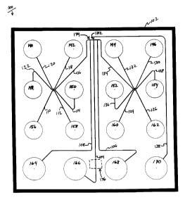
illustrated in Figure 1. As shown, the device 100, comprises a planar body
structure 102
which includes a plurality of interconnected channels disposed within its
interior, e.g.,
channels 104-138. A number of reservoirs 140-170 are also disposed in the body
structure
202 and are in fluid communication with the various channels 104-138. Samples
to be
analyzed and buffers are placed into these reservoirs for introduction into
the channels of the
device.
In operation, the separation buffer to be used in the
separation/characterization
is first placed into one reservoir, e.g., reservoir 166, and allowed to wick
into all of the
channels of the device, thereby filling these channels with the separation
buffer. Samples that
are to be separated/characterized are separately placed into reservoirs 140-
162. The
separation buffer is then placed into reservoirs 164, 168 and 170 and is
already present in
reservoir 166. Through the application of appropriate electric currents, the
first sample
material is transported or electrophoresed from its reservoir, e.g., reservoir
140, to and
through the main injection intersection 172 for channel 104, via channel 120
and 116. This is
generally accomplished by applying the current between reservoir 140 and 168.
Low level
pinching currents are typically applied at the intersection in order to
prevent diffusion of the
sample material at the intersection, e.g., by supplying a love level of
current from reservoirs
166 and 170 toward reservoir 168 (see, e.g., WO 96/04547). After a short
period of time, the
current is switched such that the material in the intersection is
electrophoresed down the main
analysis channel 104, e.g., by applying the current between reservoirs 170 and
166.
16
CA 02358683 2001-07-12
WO 00/46594 PCT/US00/02680
Typically, a slight current is applied after the injection to pull material in
channels 116 and
134 back from the intersection, to avoid leakage into the separation channel.
While the first
sample is being electrophoresed down the main channel 104, the next sample to
be analyzed
is preloaded by electrophoresing the sample material from its reservoir, e.g.,
reservoir 142,
toward preload reservoir 164 through the preload intersection 174. This allows
for only a
very short transit time to move the sample material from its preloaded
position to the
injection intersection 172. Once the first sample analysis is completed, the
second sample
material is electrophoresed across the injection intersection 172 and injected
down the main
analysis channel, as before. This process is repeated for each of the samples
loaded into the
device.
A detection zone 176 is typically provided along the main analysis channel
104, in order to provide a point at which signal may be detected from the
channel. Typically,
the devices described herein are fabricated from transparent materials. As
such, the detection
window for optically detected analyses can be located at virtually any point
along the length
of the analysis channel 104. As the separated sample passes the detection
window, the
lipophilic dye that is associated with the polypeptide fragments is detected.
The amount of
time required for each polypeptide fragment to travel through the separation
channel then
allows for the characterization of the particular polypeptide, e.g., as a
measure of its
molecular weight. In particular, the retention time of an unknown polypeptide
is compared to
the retention time of known molecular weight standards, and the approximate
molecular
weight of the unknown can be thereby determined, e.g., interpolated or
extrapolated from the
standards.
As noted previously, the post-separation treatment methods described herein
are particularly advantaged by the use of microfluidic channel systems.
Specifically,
coupling of sources of diluent to the main separation channel is a simple
matter of providing
channels connected to that channel at the appropriate location, e.g., at a
point that falls after
the separation has occurred, but before the detection zone or window. An
example of a
microfluidic channel network for accomplishing this is illustrated in Figure
7. As shown, the
microfluidic device 700 includes a body 702 that includes a channel network
disposed within
its interior portion. Typically, the device shown in Figure 7 will be
fabricated in the same
manner described above with reference to Figure 1. The channel network
includes a main
channel 704 that is in fluid communication a plurality of different sample
material reservoirs
706-722 and 728 via sample channels 706a-722a and 728a, respectively.
Preload/waste
reservoir channel/reservoirs 724/724a and 726/726a are also shown. The main
channel 704 is
17
CA 02358683 2001-07-12
WO 00/46594 PCT/US00/02680
connected to a buffer reservoir 736 and a waste reservoir 732 and includes a
detection zone
738. As shown, two diluent channels 730a and 734a are provided in
communication with
main channel 704, on opposite sides of the main channel 704, at a point
immediately
upstream (in the direction of operational flow of material) from the detection
zone, but
downstream of the major portion of the main channel 704, where the function of
that channel,
e.g., separation, occurs. Diluent channels 730a and 734a are also in
communication with
diluent sources, e.g., reservoirs 730 and 734, respectively, so as to be able
to deliver diluent
from these sources to the main channel 704.
In operation in a polypeptide separation, where one wishes to characterize a
sample, e.g., containing a polypeptide mixture, one fills the channels of the
device 700 with
the separation buffer. In the case of post separation treatment, this buffer
need not adhere to
the strictures defined above, because the concern over excessive micelle
formation is largely
lacking. Typically, in these cases, the concentration of detergent is not as
important as in the
pretreatment methods. In particular, the separation buffer can have higher
concentrations of
1 S detergent, e.g., from about 0.1 % to about 2.0%. Typically, the detergent
concentration will
be in excess of 0.1%. Filling the channel networks is typically carried out by
depositing the
separation buffer into one well, e.g., waste reservoir 732. The separation
buffer then wicks
throughout the channel network until it reaches each of the other reservoirs
706-730 and 734-
736. Optionally, slight pressure is applied to the waste reservoir 732 to
expedite filling of the
channel network. An additional quantity of buffer, e.g., separation buffer, is
placed into
buffer reservoir 736 and load/waste reservoirs 724 and 726. A diluent material
is placed into
diluent reservoirs 730 and 734.
The sample material is placed into one or more of the sample reservoirs 706-
722, and 728. Optionally, a number of different sample materials are placed
into different
reservoirs. The device is then placed into a controller/detector apparatus,
e.g., a 2100
Bioanalyzer from Agilent Technologies, which directs movement of the sample
materials
through the channels of the device, e.g., by controlled electrokinetic
methods, as described in
U.S. Patent No. 5,976,336, which is incorporated herein by reference in its
entirety for all
purposes. A sample placed into, e.g., reservoir 706 is moved along sample
channel 706a until
it crosses channel 704, and flowed toward load waste reservoir 726 via channel
726a. The
portion of the sample material at the intersection of the sample loading
channel 706a and the
main channel 704 is then injected into the separation channel 704, and moved
therethrough.
Under an applied electric field, this portion of the sample that is moving
through the
separation buffer separates into its constituent elements as it moves along
the channel 704.
18
CA 02358683 2001-07-12
WO 00/46594 PCT/US00/02680
As it travels, the sample components, and in some cases the detergent
micelles, pick up the
lipophilic dye that is present in the separation buffer. Diluent buffering
agents containing a
lower concentration or no detergent is introduced in a continuous fashion into
channel 704
via channels 730a and 734a. This diluent dilutes the separation buffer to a
point that is below
the CMC for the detergent, resulting in an elimination of excess detergent
micelles. The
diluted sample constituents bearing the lipophilic dye are then detected at
the detection
window 738. In some cases, fluidic dilution is accomplished through the actual
introduction
of fluid through the side channels. However, in preferred aspects, side
channels 730a and
734a typically contain the same separation matrix present throughout the
channel network.
As such, dilution is earned out by the electrophoretic introduction of the
ionic species from
the buffering solution are introduced electrophoretically into the separation
channel, to
effectively dilute the species in the separation channel. In alternative
aspects, the side
channels 730a and 734a are provided free of any matrices, e.g., they can
support pressure
based or electroosmotic flow, and bulk fluid is introduced into the main
channel 704, to dilute
the separated sample components. As noted, the rate at which diluent is added
to the channel
is selected to reduce the detergent concentration in the channel at the
detection point to a
level below about the CMC for the detergent under the particular conditions.
Typically, this
comprises from about a 1:2 to about a 1:30 dilution of the detergent. Thus, in
the case where
the separation buffer includes, e.g., 2 % SDS in a 30 mM Tris Tricine buffer,
it is generally
desirable to dilute the detergent level to below about 0.1% and preferably to
about 0.05%
SDS. Thus, the dilution is from about 2 to 3 fold to about 4 fold. Of course,
as noted
previously, the CMC of a particular detergent can vary depending upon the
nature and
concentration of the buffer.
Although described primarily in terms of diluting a polypeptide separation
buffer to a point that is below the CMC of the detergent in that buffer, it
will be appreciated
that the post-separation treatment methods described herein are more broadly
applicable.
Specifically, such methods can be used in a variety of analytical operations
where a
subsequent operation in a chain of analytical method steps requires a
different environment
from the immediately preceding step or operation, which environment can be
sufficiently
altered by the addition of reagents, buffers, or diluents, for that subsequent
operation. The
above-described methods illustrate an example where the environment that is
optimized for
separation of polypeptides may not be optimally compatible with the optimized
detection
environment. Thus, in accordance with the broadest understanding of this
aspect of the
invention, the term "diluent refers to an added element, e.g., fluid,
buffering agent, etc., that
19
CA 02358683 2001-07-12
WO 00/46594 PCT/US00/02680
alters the environment into which it is introduced. Alteration of an
environment in this sense
includes changing physical properties of the environment, e.g., the presence
of detergent
micelles, reducing the viscosity of a solution, but also includes changing the
chemical
envirornnent, e.g., titrating a buffer to yield a change in he pH of a
solution, e.g., to yield a
operable environment for a pH sensitive dye or other labeling species, varying
a salt
concentration of a solution to affect a change in
hydrophobicity/hydrophilicity or to affect
ionic interactions within the solution.
Similarly, labeling species may be added following an initial operation, where
such labeling species might affect the previous operation. One example of such
labeling
includes, for example, addition of labeled antibodies to specific proteins,
thereby allowing the
system to function as a chip-based western blotting system. Specifically,
following protein
separation, a labeled antibody is added to the separated proteins just prior
to detection, to
preferentially associate with a protein bearing a recognized epitope. The
protein is then
detected by virtue of its size, and its ability to be recognized by a selected
antibody.
D. Overall Systems
The devices and reagents of the present invention are typically used in
conjunction with an overall analytical system that controls and monitors the
operation and
analyses that are being carried out within the microfluidic devices and
utilizing the reagents
described herein. In particular, the overall systems typically include, in
addition to a
microfluidic device or capillary system, an electrical controller operably
coupled to the
microfluidic device or capillary element, and a detector disposed within
sensory
communication of the separation zone or channel of the device.
An example of a system according to the present invention is shown in Figure
2. As shown, the system 200 includes microfluidic device 100, which comprises
a channel
network disposed within its interior portion, where the channel network
connects a plurality
of reservoirs or sample/reagent wells. An electrical controller 202 is
operably coupled to the
microfluidic device 100 via a plurality of electrodes 204-234 which are placed
into contact
with the fluids in reservoirs of the microfluidic device 100. The electrical
controller 202
applies an appropriate electric field across the length of the separation
channel of the device
to drive the electrophoresis of the sample materials, and consequent
separation of the proteins
and polypeptides of the invention. In the case of microfluidic devices that
include
intersecting channel networks, e.g., as shown, the electrical controller also
applies electrical
currents for moving the different materials through the various channels and
for injecting
those materials into other channels. Electrical controllers that provide
selectable current
CA 02358683 2001-07-12
WO 00/46594 PCT/US00/02680
levels through the channels of the device to control material movement are
particularly
preferred for use in the present invention. Examples of such "current
controllers" are
described in detail in U.S. Patent No. 5,800,690, which is incorporated herein
by reference.
The overall system 200 also includes a detector 204 that is disposed in
sensory
communication with the separation channel portion of the channel network in
the
microfluidic device 100. As used herein, the phrase "in sensory communication"
refers to a
detector that is positioned to receive a particular signal from a channel
within a microfluidic
device. For example, in the case of microfluidic devices that are used to
perform operations
that produce optical signals, e.g., chromophoric, fluorescent or
chemiluminescent signals, the
detector is positioned adjacent to a translucent portion of the device such
that optical
elements within the detector receive these optical signals from the
appropriate portion of the
microfluidic device. Electrochemical detectors, on the other hand, in order to
be in sensory
communication, typically include electrochemical sensors, e.g., electrodes,
disposed within
the appropriate channels) of the device, so as to be able to sense
electrochemical signals that
are produced r otherwise exist within that channel. Similarly, detectors for
sensing
temperature will be in thermal communication with the channels of the device,
so as to sense
temperature or relative changes therein. In preferred aspects, optical
detectors are employed
in the systems of the present invention, and more preferably, optical
detectors that are
configured for the detection of fluorescent signals. As such, these detectors
typically include
a light source and an optical train for directing an activation light at the
separation channel, a.s
well as an optical train and light sensor, for collecting, transmitting and
quantifying an
amount of fluorescence emitted from the separation channel. In general, a
single optical train
is utilized for transmission of both the activation light and the fluorescent
emission, relying
upon differences in wavelengths of the two types of energy to distinguish
them. Generally,
optical sensors incorporated into the optical detectors of the present
invention are selected
from these that are well known in the art, such as photomultiplier tubes (PMT)
photodiodes,
and the like. In particularly preferred aspects, an Agilent 2100 Bioanalyzer
is used as the
controller/detector system (Agilent Technologies).
The systems described herein also typically include a processor or computer
206 operably coupled to the electrical controller, for instructing the
operation of the electrical
controller in accordance with user instructions or preprogrammed operating
parameters. The
computer is also typically operably coupled to the detector for receiving and
analyzing data
that the detector receives from the microfluidic device. Accordingly, the
computer typically
includes appropriate programming for directing the operation of the electrical
controller to
21
CA 02358683 2001-07-12
WO 00/46594 PCT/US00/02680
apply electric fields to inject each of a potential plurality of samples into
the separation
channel. Typically, the computer also is operably coupled to the detector so
as to receive the
data from the detector and to record the signals received by the detector.
Processor or
computer 206 rnay be any of a variety of different types of processors.
Typically, the
computer/processor is a IBM PC or PC compatible computer, incorporating an
microprocessor from, e.g., Intel or Advanced Microdevices, e.g., PentiumTM or
K6TM, or a
MacIntoshTM, ImacTM or compatible computer.
In the case of the polypeptide characterization methods of the present
invention, the computer or processor is typically programmed to receive signal
data from the
detector, and to identify the signal peaks that correspond to a separated
protein passing the
detector. Typically, one or more internal standard proteins may be run along
with the sample
material. In such cases, the computer is typically programmed to identify the
standards) e.g.,
by its location in the overall separation, either first or last, and to
determine the molecular
weights of the unknown polypeptides in the sample by extrapolation or
interpolation from the
1 S standard(s). A particularly useful computer software program for use in
accordance with the
present invention is described for use with separation methods, in Provisional
Patent
Application No. 60/068,980, filed December 30, 1997, and incorporated herein
by reference.
In the case of those embodiments run on an Agilent 2100 Bioanalyzer, the
computer typically
includes software programming similar to that offered used to run these
systems for nucleic
acid analysis.
E. Kits
The present invention also provides kits for use in carrying out the described
methods. Generally, such kits include a capillary or microfluidic device as
described herein.
The kits also typically include the various components of the separation
buffer, e.g., the non-
crosslinked polymer sieving matrix, detergent, buffering agent and the
lipophilic dye. These
components may be present in the kit as separate volumes of preformulated
buffer
components, which may or may not be pre-measured, or they may be provided as
volumes of
combined preformulated reagents up to and including a single combination of
all of the
reagents, whereby a user can simply place the separation buffer directly into
the microfluidic
device. In addition to the buffer components, kits according to the present
invention also
optionally include other useful reagents, such as molecular weight standards,
as well as tools
for use with the devices and systems, e.g., instruments which aid in
introducing buffers,
samples or other reagents into the channels of a microfluidic device.
22
CA 02358683 2001-07-12
WO 00/46594 PCT/US00/02680
In the kit form, the reagents, device and instructions detailing the use
thereof
are typically provided in a single packaging unit, e.g., box or pouch, and
sold together.
Provision of the reagents and devices as a kit provides the user with ready-to-
use, less
expensive systems where the reagents are provided in more convenient volumes,
and have all
been optimally formulated for the desired applications, e.g., separation of
high molecular
weight vs. low molecular weight proteins.
The present invention is further illustrated with reference to the following
examples which demonstrate certain aspects of the invention without limiting
the scope of
that invention.
EXAMPLES
All experiments were performed in a twelve sample microfluidic device
having a single separation channel and the channel geometry illustrated in
Figure 1. Control
and detection were performed using a multichannel, twelve electrode electrical
controller/detector having a single point laser fluorescence detector located
along the single
separation channel.
Example 1: Separation of Polwentides Using SubCMC Separation Buffer
Fluorescence data received from the separation channel was recorded by a
computer (PC with Intel Pentium~ microprocessor). The data was displayed in
both a linear
plot of fluorescence vs. time as well as in an emulated gel format generated
by Caliper
Technologies Corp. proprietary software.
A 0.5 M solution of Tris-Tricine buffer was prepared by dissolving Tricine in
deionized water at a 0.5 M concentration, and adjusting the pH to 7.5 with 1 M
Tris. The
resulting buffer was then filtered through a 0.22 ~m syringe filter. The
sieving or separation
buffer was prepared at 3% polydimethylacrylamide-coacrylic acid in 12.5 mM
Tris-Tricine
buffer with 0.9 % (w/v) sodium dodecyl sulfate (SDS), and 10 ~.M Syto 60 dye
(Molecular
Probes, Eugene OR). The separation buffer was then filtered through a Costar
Spin-XTM 0.22
~m cellulose acetate centrifuge filter.
Samples were pretreated in denaturation buffer prior to placement into the
reservoirs of the device. The denaturation buffer was 0.75% SDS (w/v) and 1% 2-
mercaptoethanol (v/v)(BME) in 250 mM Tris-Tricine buffer. The samples were
mixed 1:1
with denaturation buffer (e.g., 20 ~1 sample and 20 ~l buffer) in a 0.5 ml
microfuge tube and
heated to 100°C for 10 minutes. The heated samples were then
centrifuged and vortexed.
23
CA 02358683 2001-07-12
WO 00/46594 PCT/US00/02680
Prior to loading the samples into the wells of the microfluidic device, they
were diluted 1:10
with deionized water, e.g., 1 ~,1 sample/buffer and 9 ~,l water). The prepared
samples
therefore had a detergent concentration of 0.0375% SDS.
To prepare the microfluidic device, 7.5 ~l of separation buffer was pipetted
into well 166 of a clean, dry device, and pressurized with a syringe to force
the separation
buffer into all of the channels of the device. 7.5 ~,l of separation buffer
was then pipetted into
each of wells 164, 168 and 170. 0.5 ~,l of the diluted samples were then
separately pipetted
into each of wells 140-162. In the example shown in Figure 4, standards of
known molecular
weight were used. The standards included ovalbumin (45 kD), bovine carbonic
anhydrase
(29 kD), soybean trypsin inhibitor (21.5 kD) and a-lactalbumin (14.4kD).
With reference to Figure 1, wells 142 and 146 contained only buffer, and were
used as blanks. A standard protein solution containing 100 ~g/ml of each of
the four protein
standards was placed into each of wells 150 and 154, while a solution of the
same four
proteins at 500 p.g/ml was placed into wells 158 and 162. A solution
containing just the
carbonic anhydrase standard at 1000 p.g/ml was placed into wells 140 and 144.
A solution
containing both carbonic anhydrase and trypsin inhibitor at 100 pg/ml, was
placed into wells
148 and 152, while a solution containing the same proteins, but at 500 ~,g/ml
was placed into
wells 1 S 6 and 160.
Each sample was separately injected down the main separation channel 104
and the separated components were detected as a function of retention time
from injection.
The chromatogram for each run was displayed in the form of dark bands intended
to emulate
a standard coomassie stained SDS-PAGE gel. Each lane of the emulated gel
represents a
chromatogram for a separate sample, with the dark bands indicating increases
in fluorescence
over background. In particular, a mixture of ovalbumin (45 kD), bovine
carbonic anhydrase
(29 kD), soybean trypsin inhibitor (21.5 kD) and a-lactalbumin (14.4kD) was
prepared. The
two different concentrations of the four protein mix were run at 100 ~g/ml
(Lane A2, well
154) and 500 p,g/ml (Lane A3, well 162). Separate mixtures of each of these
standards were
also prepared and run as follows:
Lane B1 (well 144): Carbonic Anhydrase (1 mg/ml)
Lane B2 (well 152): Trypsin Inhibitor and Carbonic
anhydrase (both at 100/p.g/ml)
Lane B3 (well 160): Same as B2 (both at 500 pg/ml)
24
CA 02358683 2001-07-12
WO 00/46594 PCT/US00/02680
Lane C2 (well 142): Same as Lane A2
Lane C3 (well 150): Same as Lane A3
Lane D1-D3 (wells 140-156): Same as Bl-B3
Figure 5 shows a plot of the log of the molecular weight versus the migration
time for a set of
standards run in the same fashion as described above. As can be seen, the
separation methods
described yield accurate, e.g., linear data, which permits the
characterization of proteins of
unknown molecular weight, by correlating the migration times for those unknown
proteins
with the set of standards, in accordance with the plot shown. As can be seen
from Figures 4
and 5, a highly reproducible, accurate and rapid method is provided for
characterizing
proteins and other polypeptides.
The same set of standards, also including a Cy-5 dye marker was also run to
show the co-elution of the detergent dye front. The chromatogram from this run
is shown in
Figure 6. As can be seen, the detergent-dye peak (indicated with an asterisk)
elutes at
substantially the same time as proteins having a molecular weight of in the
range of 65 kD.
In those instances where the detergent concentration in the sample
pretreatment buffer is at
levels previously described in the art, e.g., 2 %, the indicated peak is much
larger, and that
peak substantially interferes with the identification and quantitation of
proteins in this
molecular weight range.
Example 2: Separation and Detection of Polypeptides Using Post-Separation/Pre-
Detection Dilution
A microfluidic device as shown in Figure 7, was filled with a separation
buffer
as described above. The separation channel 704 is intersected by the diluent
channels 720a
and 722a at point 1.2 cm downstream from the injection point, and O.lcm
upstream of the
detection point 732. The separation buffer contained 4.2 % non-crosslinked
polydimethylacrylamide/ co-acrylic acid in 30 mM Tris Tricine buffer, and
0.13% SDS. The
dilution buffer, which comprised 30 mM Tris-Tricine with no polymer or SDS,
was placed
into reservoirs 720 and 722. The buffering agent was flowed into the
separation channel
electrokinetically, e.g., electrophoretically.
A polypeptide standard solution (10-205kD protein standard from Bio-Rad,
Inc.) was placed into a sample reservoir , e.g., reservoir 706, and loaded and
injected into the
separation channel using the same methods described in U.S. Patent 5,976,336,
previously
incorporated herein.
CA 02358683 2001-07-12
WO 00/46594 PCT/US00/02680
Figures 8A-8D illustrates plots of fluorescence versus time, as detected at
the
detection point 732 in a 2100 Bioanalyzer (Agilent Technologies, Inc.) for a
standard
separation performed without a post separation treatment and with a post
separation dilution.
Specifically, Figures 8A and B show a blank run (no polypeptides in the
sample) and a
protein sample run in a microfluidic device having no post separation dilution
functionality.
The device was functionally similar to the device channel layout shown in
Figure 1. As
shown, the data from the blank and polypeptide runs included substantial
background and
other baseline problems including a large detergent dye front, followed by a
baseline divot
and a following dye hump. These same baseline deviations were found in the
sample
separation run, which cause substantial difficulty in qualifying and
quantifying the
separation data. Figures 8C and 8D illustrate the same blank run and
polypeptide sample
analysis using a post separation dilution step where the Tris Tricine buffer
was introduced
into the separation channel downstream of the majority of the separation, but
upstream of the
detection point. As shown, the post-separation dilution step substantially
reduces overall
background fluorescence relative to the detected sample components over the
non-diluted
samples, while also reducing the baseline humps and dips that are associated
with micelle dye
binding, e.g., as seen in Figures 8A and 8B.
Unless otherwise specifically noted, all concentration values provided herein
refer to the concentration of a given component as that component was added to
a mixture or
solution independent of any conversion, dissociation, reaction of that
component to a alter the
component or transform that component into one or more different species once
added to the
mixture or solution.
All publications and patent applications are herein incorporated by reference
to the same extent as if each individual publication or patent application was
specifically and
individually indicated to be incorporated by reference. Although the present
invention has
been described in some detail by way of illustration and example for purposes
of clarity and
understanding, it will be apparent that certain changes and modifications may
be practiced
within the scope of the appended claims.
26