Note: Descriptions are shown in the official language in which they were submitted.
CA 02358994 2001-07-19
1
PIPE COT1PLING FOR PLASTICS PIPES
The invention relates to a pipe coupling of glass-fibre
-reinforced plastics material and a membrane of elastic
material which is formed as a seal at least at one end.
From EP 0 651 506 B1 there is known a socket provided
with a sealing sleeve for the connection of two plastics
pipes, which is developed from a prior art coupling in which
the two identically formed part sections each for the
receiving of a pipe end are substantially equal in length.
The known socket has two significantly different length
cylindrical end sections (e. g. preferably with length ratio
1:3 and smaller) and between these is an annular recess in
which the sealing sleeve is set. The sealing sleeve has at
each end section a sealing lip between which extends a
cylindrical section. This is divided by a rib which projects
into the interior of the socket into a shorter part adjacent
to the longer end region and into a longer part adjacent to
the shorter end region.
From US 4 642 156 there is known a method for the
manufacture of a sealing sleeve which comprises a stop rib and
sealing lips, but no cylindrical section.
From US-A-5 330 238 there is known a pipe coupling comprising
a sleeve having a substantially cylindrical outer layer 22 of
glass-fibre reinforced plastics material and of an inner layer
23 of polyurethane. When the pipes are slid on each other the
interior of the sleeve is deformed and the polyurethane layer
23 is compressed to a conically widening sleeve surface 27
particularly in the region of two circumferentially provided
flat sealing bE:ads 28 and 29. At one end a cylindrical section
CA 02358994 2001-07-19
2
33 is provided which can be provided with a bevel 34. An an-
chorage of the inner layer 23 is not provided so that the po-
sitional stability of the pipe coupling depends on the bond of
the inner layer 23 to the outer layer 22. Therefore, the pipe
coupling cannot be used at high interior pressures, but only
in depressurized systems.
A sleeve known from EP 0 787 93'7 is formed as a sealing collar
having a substantially cylindrical shape, which is provided
with a sealing bead 35 and has a rib 32 in the centre. The
sealing beads are provided for locally increasing the pressure
and for assuring a sufficient sealing contact.
In US 4 513 996 a tube coupling is described the sleeve part
of which ends in an outwardly widening annular flange. The
membrane is adapted conforming to the sleeve shape and is pro-
vided with ribs which engage grooves of the sleeve. Neither
the wall thickness of the membrane, nor the diameter are con-
stant whereby in some zones peak loads are obtained. Since the
membrane is only joined with the sleeve by grooves and ribs,
but is not anchored there and also is not supported in its end
portions, a delamination and a blowing-off of the membrane
tend to occur at higher inner pressures.
It is the object of the invention to provide a pipe
coupling which can be used at high pressures, particularly
internal pressures of 2,5 to 5,0 Ira (25 to 50 bar), without causing damage to
the coupling by expansion of the pipe as a result of increased
interna7_ pressure, and wherein the pipe coupling can be used
also with offset and/or angled pipe axes.
Thz_s object is achieved in accordance with the invention
by a pipe coupling hawing the feature~~ of cl ~~i;r, 1 . Preferred
CA 02358994 2001-07-19
3
features of the pipe coupling according to the invention are
t:he subject of the dependent claims.
A pipe coupling according to the invention comprises a
socket of glass-fibre reinforced plastics material and a
membrane of elastic material which is formed as a seal at at
least one end and comprises a sleeve section. Where the
membrane is formed as a seal, at the end of the membrane,
where the pipe is to be introduced (i.e. at the outer end),
there is a short cylindrical band of the membrane . In the
cylindrical band the membrane has a constant wall thickness,
which is bacJced by the glass-fibre reinforced socket material
oz the pipe coupling. Outside the cylindrical band, the further
structure of the pipe coupling is such that an angle is
present cahich is at least as large as the permitted angled
orientation of the coupling, and the membrane is anchored in
the socket over this angled part. This makes possible the
connection of pipes even with longitudinal axes which are
offset relative to one another and/or extend at an angle.
The pipe coupling of the present invention is suitable
for use at high pressures, appror:imately 1,5 to 5,0 NiPa
(15 to 50 bar) (depending upon the pipe diameter). t~dith the structure of the
pipe coupling provided according to the invention, a reliable
connection and sealing of plastics pipes, particularly GFK
pipes based on glass-fibre reinforced plastics material, is
possible because the short cylindrical band frees the sealing
portion f~.~om load. Because of the short length of this
membrane section, in the event of expansion, i.e. widening of
the pipe in diameter, this section expands in the longitudinal_
direction in response thereto, as a reaction, w-~th the result
CA 02358994 2001-07-19
4
that the socket is not mechanically stressed by the widening
of the pipe. The expansion stroke of the pipe directed
towards the socket is thus counterbalanced.
If the cylindrical section is arranged at a small angle,
then an angled orientation of a connected pipe is possible.
However, a disadvantageous pressure is then exerted on the
socket.
Alternatively, only one end may be provided with an
angled configuration as mentioned above, with the other end
permitting no angled orientation of a pipe. Then, there is
basically an angled orientation between pipe and coupling at
the one end and at the other end only a telescopic movement
of the pipe located in the coupling is possible.
Preferably, the dimensioning of the materials is such
that with an internal pressure in the pipe of 1.0 x PN (0.098 I~a~0.98 bar)
up to l.5 x PN (0.147 MPa~1.47 barJ) (nominal pressure) the pipe is in contact
with the cylindrical band of the pipe coupling without pressure.
At the end where no angled orientation is provided for,
the seal can be provided by a ring of_ elastic material with
sealing elements fitted at the forward end of a pipe to be
coupled, and the sealing elements effect a seal with the
membrane of elastic material of the coupling.
Preferably, the membrane and/or the ring provided with
sealing elements is or are of rubber which ensures a
particularly reliable sealing against the passage of foreign
material.
The invention will now be described by means of examples
and with reference to the drawings. These are intended to
illustrate the scope of_ the invention and should z:ot be
CA 02358994 2001-07-19
interpreted any limiting sense. In the dra~.aings:
in
Fig. 1 i s a schematic sectional vie w, through a pipe
coupling whichis made according to a first embodiment of the
invention;
and
Fig. 2 is a a pipe
schematic
sectional
view through
coupling whichis made according to a secondembodiment of the
invention.
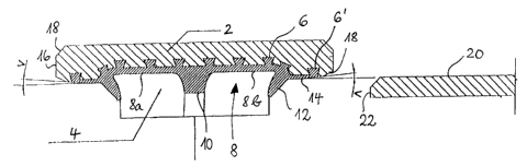
Fig. ~. shows a pipe coupling which permits an angled
orientation between pipe and coupling at both ends. The pipe
coupling comprises a substantially cylindrical socket 2 of
glass-fibre reinforced plastics material. On its inside the
socket has a recess in which a membrane 4 of elastic material,
here rubber, is received to serve as a seal. The membrane 4
is anchored in the socket 2 by means of annular beads 6. It
has a central cylindrical sleeve section 8 which is divided
into two substantially equal length sleeve sections 8a, 8b by
an inwardly projecting rib 10. The central sleeve section 8
is bounded by two sealing lips 12. Outside the sealing lips
12 there extends at each end a short cylindrical band 14 of
reduced wall thickness which is anchored at the end by one 6'
of the aforementioned annular beads 6. The internal diameter
of the short cylindrical bands 14 is smaller than that of the
central cylindrical sleeve section 8. From the region of the
outermost annular bead 6' the end of the socket tapers at an
angle V, with the socket having at etch end a chamfer 18 ~:t
the transitions from the taper to the end faces 16. In Fig.
1, at the right-hand side, there is shown schematically a part
of a wall of a pipe or pipe end 20 which is to be connected
by the pipe coupling.
CA 02358994 2001-07-19
6
As is evident from the drawing, the external wall of tha
pipe 20 is substantially in alignment with the wall of the
short cylindrical band 14. G~Ihen the pipe 20 is pushed in, the
sealing lip 12 is flattened, thereby achieving a sealing
action, and with the sealing lip material being compressed.
Provided that the pipe 20 is pushed into the pipe coupling
sufficiently far, in its final position it has its end face
22 abutting against the rib 10.. Due to the possibility of
angled orientation through the angle V it is possible, upon
inserting the pipe 20, to introduce the pipe at an appropriate
angle, maximum V, to the longitudinal axis of the coupling,
with the result that one can compensate for tolerances caused
for example by the installation.
In the embodiment according to Fig. 2, one of the two
sealing lips 12 of the central sleeve section 8 of the
membrane 4 of the first embodiment is omitted (here the right
hand sealing lip). The sleeve section Sb which here lies at
the opposite end to the sealing lip 12 has a smaller internal
diameter than the sleeve section 8a between the sealing lip
12 and the rib 10. The outer wall of the membrane 4 in the
region of the rib tapers inwardly towards the plain sleeve
section 8b. At the outside of the sealing lip 12 there is a
short cylindrical band 14 as in the embodiment described
above. Adjacent to the plain section 8b of the central sleeve
section there is an inner wall region of the socket 2 which
is aligned with the inner wall of the plain sleeve section 8b.
The angled nature of the socket at the outer ends (angle V)
and the chamfers 18 art provided as in the embodiment
described above.
The pipe 20, which here again is only shown
schematically, has a some~~ahat greater wall thickness. Spaced
CA 02358994 2001-07-19
7
somewhat from the end face 22 of the pipe there is located an
annular recess in which a sealing ring 24 of rubber is fitted.
The sealing ring 24 comprises two spaced annular beads 26
which serve as sealing elements. These come into sealing
engagement with the plain section 8b of the central sleeve
section 8 when the pipe is pushed into the long end of the
coupling.
As mentioned above, the sealing at the long end of the
coupling is maintained by the rubber ring 24. As Fig. 2
shows, the sealing is maintained by two solid annular beads.
Alternatively, lip seals or a combination of semi-cylindrical
beads and lips could be used. The rubber ring 24 is so
positioned that the seal is effected against the rubber
membrane 4 in the coupling. The reason for this will be
explained hereinafter.
At the short end of the coupling, the sealing is effected
by the lip 12 which is a part of the rubber membrane 4. The
rubber membrane 4 is extended sufficiently far that it goes
beyond the sleeve section 8.
The dimensioning is so planned that with an internal
pressure of 1.0 x PN to 1.5 x PN (nominal pressure: 0.098 to 0.147
MPa~,0.98 to 1.47 bar) the gaps between the internal diameter of the
cylindrical band 14 and the external diameter of the pipe 20
(Fig. 1) and between the internal diameter of the plain sleeve
section 8b and the pipe external diameter (Fig. 2) are zero.
If this dimensioning is adopted, then with a nominal pressure
PN the elongation as a result of internal pressure has a
certain established value. Unfortunately, this value is not
always constant, but has large deviations. This leads to
creepage with time. It can happen that in use the pipe ends
CA 02358994 2001-07-19
a
press tremendously against the coupling. Because of this the
rubber ring 24 at the end of the pipe must press against the
rubber membrane 4, since here otherwise forces which are too
large would occur in the coupling. At the small end (which
has the sealing lip 12) it is sufficient if rubber of
sufficient thickness is provided for the cylindrical band 14.
The thickness should be at least 2 mm. It is important that
the cylindrical band 14 is very short, so that the rubber can
extend in the longitudinal direction if pressed too hard. An
important dimension is that of the angle V. This should be
equal to the permitted angled orientation of the coupling.
The rubber membrane 4 should on top of that be anchored in the
sleeve portion in this region.
It is important that the anchoring of the short
cylindrical band 14 is in the angled part and not in the
cylindrical part, since resin can penetrate under the rubber
at the angle, which would be dangerous if such resin was
present in the cylindrical part.
In order to prevent such penetration, it is advantageous
if the angle V is smaller in section than the planned angle.