Language selection

Search

Patent 2359351 Summary

Third-party information liability

Some of the information on this Web page has been provided by external sources. The Government of Canada is not responsible for the accuracy, reliability or currency of the information supplied by external sources. Users wishing to rely upon this information should consult directly with the source of the information. Content provided by external sources is not subject to official languages, privacy and accessibility requirements.

Claims and Abstract availability

Any discrepancies in the text and image of the Claims and Abstract are due to differing posting times. Text of the Claims and Abstract are posted:

  • At the time the application is open to public inspection;
  • At the time of issue of the patent (grant).
(12) Patent Application: (11) CA 2359351
(54) English Title: DOOR CLOSER MOUNTING BRACKET WITH SCREW HOLDERS
(54) French Title: SUPPORT DE FIXATION POUR FERME-PORTE AVEC DISPOSITIFS PORTE-VIS
Status: Deemed Abandoned and Beyond the Period of Reinstatement - Pending Response to Notice of Disregarded Communication
Bibliographic Data
(51) International Patent Classification (IPC):
  • E05F 3/00 (2006.01)
  • F16B 41/00 (2006.01)
(72) Inventors :
  • LASSON, REX H. (United States of America)
  • ANDERSON, TOM (United States of America)
  • BRAUNLICH, MARK F. (United States of America)
  • CURRENT, ANDREW (United States of America)
  • JENSEN, JAMES E. (United States of America)
(73) Owners :
  • SCHLAGE LOCK COMPANY
(71) Applicants :
  • SCHLAGE LOCK COMPANY (United States of America)
(74) Agent: SMART & BIGGAR LP
(74) Associate agent:
(45) Issued:
(86) PCT Filing Date: 2000-01-06
(87) Open to Public Inspection: 2000-07-20
Availability of licence: N/A
Dedicated to the Public: N/A
(25) Language of filing: English

Patent Cooperation Treaty (PCT): Yes
(86) PCT Filing Number: PCT/IB2000/000013
(87) International Publication Number: WO 2000042281
(85) National Entry: 2001-07-04

(30) Application Priority Data:
Application No. Country/Territory Date
60/115,334 (United States of America) 1999-01-11

Abstracts

English Abstract


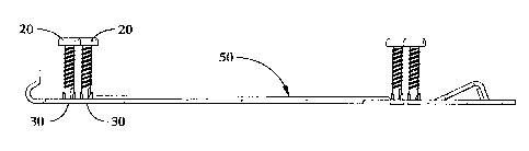
A door closer mounting bracket which includes a screw holder for holding the
mounting screws in the proper installation position. The screw holder
eliminates the need for the installer to hold the mounting bracket with one
hand, hold a screw in the proper position with the same hand and then attach
the screw to the door with a screw driver in the other hand. The preferred
screw holder is a plastic grommet plug in each mounting hole. The plastic
grommet plug further includes a plurality of upwardly extending posts to
better grip and retain the screws.


French Abstract

L'invention concerne un support de ferme-porte comprenant un dispositif porte-vis destiné à maintenir les vis de montage dans la bonne position d'installation. Grâce à ce porte-vis, l'utilisateur ne doit plus tenir le support de fixation et maintenir une vis dans la bonne position de montage avec la même main pour ensuite visser la vis à la porte à l'aide d'un tournevis dans l'autre main. Le porte-vis préféré de l'invention se constitue d'un bouchon à oeillet en plastique dans chaque trou de fixation. Ces bouchons à oeillet comprennent également plusieurs colonnettes s'étendant vers le haut, qui permettent une meilleure prise et maintiennent les vis.

Claims

Note: Claims are shown in the official language in which they were submitted.


Having described the invention, what is claimed is:
1. In combination:
a door closer;
a mounting bracket adapted to engage the door closer, the
mounting bracket having a plurality of mounting holes therethrough;
a plurality of screws; and
a holder means for temporarily retaining the screws in pre-
installation positions aligned with the mounting holes.
2. The combination according to claim 1, wherein the holder means
comprises a plastic plug inserted into a mounting hole, the plastic
plug grippingly engaging the screw.
3. The combination according to claim 2, wherein the plastic plug
has a plurality of posts extending therefrom, the posts supporting
and guiding the screw.
4. The combination according to claim 3, wherein the posts are
bendable.
5. The combination according to claim 3, wherein the head of the
screw engages the posts when the screw is driven into a mounting
substrate, the screw head bending and breaking the posts.
6. The combination according to claim 1, wherein the holder means
comprises a crushable material removably attached to the mounting
bracket, the screw being inserted into the crushable material.
7. The combination according to claim 6, wherein the crushable
material is a foam block.
8. The combination according to claim 1, wherein the holder means
comprises a thin walled sleeve engaging a mounting hole and a
screw.
9. The combination according to claim 8, wherein the sleeve is
-6-

formed from a crushable material.
10. The combination according to claim 9, wherein the sleeve is
plastic.
11. The combination according to claim 8, wherein the sleeve is
tapered.
12. The combination according to claim 1, wherein the holder means
comprises a thin walled tube attached about a mounting hole, the
tube engaging a head of the screw.
13. The combination according to claim 12, wherein the tube is
metal and is tack welded to the mounting bracket.
14. The combination according to claim 1, wherein the holder means
comprises a plurality of inwardly extending screw engaging tabs
about the circumference of a mounting hole.
15. The combination according to claim 14, wherein the tabs are
frangible.
16. The combination according to claim 1, wherein the holder means
comprises a tag adjacent a bottom side of the mounting bracket, the
tag engaging one or more screws, the screws being inserted through
the mounting holes from a top side of the mounting bracket and into
the tag.
17. The combination according to claim 16, wherein the tag is
cardboard.
18. The combination according to claim 1, wherein the holder means
comprises a shell attached to the mounting bracket, the shell
having an upper surface positioned distal the mounting bracket and
having a plurality of screw engaging projections extending from the
upper surface towards the mounting bracket, the screws being
-7-

retained within and by the screw engaging projections.
19. The combination according to claim 18, wherein the shell is
plastic.
20. The combination according to claim 18, wherein the screw
engaging projections are funnel shaped.
-8-

Description

Note: Descriptions are shown in the official language in which they were submitted.


CA 02359351 2001-07-04
WO 00/42281 PCT/IB00/00013
DOOR CLOSER MOUNTING BRACKET WITH SCREW HOLDERS
BACKGROUND OF THE INVENTION
This invention relates generally to the installation of door
closers and more particularly to the installation of door closer
mounting brackets.
The typical installation of a door closer requires the
installer to measure and mark the door and door frame for the
mounting screws. Next, the installer drills holes for the mounting
screws. He holds the door closer to the door or door frame with
one hand, picks up the screws and attempts to hold the door closer
and screws with one hand while using a screw driver to screw the
screws into the door. Typically, door closers can weigh up to 8
to 10 pounds. Holding the door closer and the screws with one hand
while attaching the screws to the door with the other hand can make
the installation difficult.
The foregoing illustrates limitations known to exist in
present door closer installations. Thus, it is apparent that it
would be advantageous to provide an alternative directed to
overcoming one or more of the limitations set forth above.
Accordingly, a suitable alternative is provided including features
more fully disclosed hereinafter.
SUMMARY OF THE INVENTION
In one aspect of the present invention, this is accomplished
by providing in combination: a door closer; a mounting bracket
adapted to engage the door closer, the mounting bracket having a
plurality of mounting holes therethrough; a plurality of screws;
and a holder means for temporarily retaining the screws in pre-
installation positions aligned with the mounting holes.
The foregoing and other aspects will become apparent from the
-1-
CONFIRMATION COPY

CA 02359351 2001-07-04
WO 00/42281 PCT/IB00/00013
following detailed description of the invention when considered in
conjunction with the accompanying drawing figures.
BRIEF DESCRIPTION~OF THE DRAWING FIGURES
FIG. 1 is perspective view of a door closer and mounting
bracket;
FIG. 2 is a top view of the mounting bracket shown in FIG. 1;
FIG. 3 is a side view of the mounting bracket shown in FIG.
1;
FIG. 4 is a side view of the mounting bracket shown in FIG.
1 showing a first embodiment of a screw holder according to the
present invention;
FIGS. 4A and 4B are top and side views of the screw retaining
plug shown in FIG. 4;
FIGS. 5A and 5B are top and side views of a second embodiment
of a screw holder according to the present invention;
FIGS. 6A and 6B are top and side views of a third embodiment
of a screw holder according to the present invention;
FIG. 7 is a side view of a fourth embodiment of a screw holder
according to the present invention;
FIG. 8A and 8B are top and side views of a fifth embodiment
of a screw holder according to the present invention;
FIGS. 9A and 9B are bottom and side views of a sixth embodi-
ment of a screw holder according to the present invention; and
FIGS. l0A and 10B are top and side views of a seventh
-2-

CA 02359351 2001-07-04
WO 00/42281 PCT/IB00/00013
embodiment of a screw holder according to the present invention.
DETAILED DESCRIPTION
FIG. 1 shows a preferred embodiment of a door closer 10 with
a cylinder body 12 and its relationship to mounting bracket 50.
The screw holders of the present invention can be used with any of
the many different types of door closer mounting brackets. One end
the door closer 10 has a lip 14 which engages an angle clamp or
hook portion 60 on one end of the mounting bracket 50. The other
end of the door closer 10 includes a screw passageway (not shown)
that engages the screw 58 on the mounting bracket 50. The screw
58 is threaded into a screw attachment 54.
The door closer 10 fits into bracket 50 such that both hands
are available to secure the attachment fastener. First, the four
holes for the mounting bracket 50 are drilled into either the door
or the door frame. Then, the mounting bracket 50 is attached to
the door or door frame using screws 20 (which are held in pre-
installation positions by screw holders shown in FIGS. 4 through
lOB) inserted into mounting holes 70. The door closer lip 14 is
inserted into the hook 60 and the other end of the door closer 10
is swung down onto the screw 58, as shown in FIG. 1. The hook 60
and lip 14 in cooperation with the screw 58 and screw passageway
hold the door closer 10 loosely against the mounting bracket 50
until screw 58 can be turned to tightened the door closer 10 to the
mounting bracket 50.
FIGS. 4, 4A and 4B show the preferred embodiment of the screw
holder. Plastic grommet plugs 30 are inserted into each mounting
hole 70. A screw 20 is then inserted into each grommet plug 30,
the plug 30 gripping and retaining the screw 20. Preferably plug
30 includes a plurality of upwardly extending posts 32 which
provide better gripping and retention of the screw 20. The posts
32 are bendable and as the head of the screw 20 contacts posts 32,
the posts 32 are bent outwardly and them broken off by the force
-3-

CA 02359351 2001-07-04
WO 00/42281 PCT/IB00/00013
of the screw head.
FIGS. 5A and 5B show a second embodiment of the screw holder.
A plastic shell 34 is snapped onto the mounting bracket 50 engaging
the hook 60 and the screw 58 and screw attachment 54. The plastic
shell 34 includes a plurality of funnel shaped downwardly projec-
tions 36. Each projection 36 grippingly engages and retains a
screw 20. The material of plastic shell 34 is sufficiently
resilient to allow the material in projections 36 to deform when
the screws 20 are driven into the door, thereby permitting the
screws 20 to be completely tightened against the mounting bracket
50. Preferably, projections 36 do not extend completely to the
upper surface of mounting bracket 50. This permits shell 34 to be
easily removed from mounting bracket 50 after the mounting bracket
50 is attached to the door. In addition to retaining screws 20,
shell 34 can be provided with additional inwardly extending
projections to hold other mounting hardware 51.
FIGS. 6A and 6B show a third embodiment of a screw holder.
A crushable foam block 38 is attached to the mounting bracket 50.
Depending on the location of mounting holes 70, the foam block 38
is positioned over one or more mounting holes 70. Screws 20 are
then screwed into the foam block 38 over the mounting holes 70.
As the screws 20 are screwed into the door, the foam about the
screws 20 is crushed so that it doesn't interfere with attaching
the screws 20. After the mounting bracket 50 is attached to the
door, the foam block 38 is removed from the mounting bracket 50.
FIG. 7 shows a fourth embodiment of the screw holder. A thin
walled grommet type screw sleeve 40 is attached to each mounting
hole 70. Sleeve 40 contains one or more grommet type projections
at its lower end to grip mounting hole 70, thereby retaining the
sleeve 40 on the mounting bracket 50. Preferably, sleeve 40
contains a tapered portion 41 to provide better gripping and
retention of screw 20. Also preferably, sleeve 40 is formed from
a crushable material such as plastic or thin walled metal.
-4-

CA 02359351 2001-07-04
WO 00/42281 PCT/IB00/00013
FIGS. 8A and 8B show a fifth embodiment of the screw holder.
A thin walled steel tube 42 is tack welded to the mounting bracket
50 at one or more locations 43. Tube 42 extends upwardly to engage
the head of screw 20 at a head engaging portion 44. The tube is
broken off after the screws are installed.
FIGS. 9A and 9B show a sixth embodiment of the screw holder.
Each mounting hole 70 has a plurality of inwardly extending tabs
46 which engage the end of screw 2Q to hold the screws 20 to the
mounting bracket 50 prior to installation. Preferably, tabs 46 are
frangible.
FIGS. l0A and lOB show a seventh embodiment of the screw
holder. A tag 48 is provided on the underside of the mounting
bracket 50. Preferably, tag 48 is a piece of cardboard. Screws
are partially driven through tag 48, which then retains screws
20 prior to installation. Tag 48 may or may not be adhesively
attached to mounting bracket 50.
-5-

Representative Drawing
A single figure which represents the drawing illustrating the invention.
Administrative Status

2024-08-01:As part of the Next Generation Patents (NGP) transition, the Canadian Patents Database (CPD) now contains a more detailed Event History, which replicates the Event Log of our new back-office solution.

Please note that "Inactive:" events refers to events no longer in use in our new back-office solution.

For a clearer understanding of the status of the application/patent presented on this page, the site Disclaimer , as well as the definitions for Patent , Event History , Maintenance Fee  and Payment History  should be consulted.

Event History

Description Date
Inactive: IPC from MCD 2006-03-12
Application Not Reinstated by Deadline 2004-01-06
Time Limit for Reversal Expired 2004-01-06
Deemed Abandoned - Failure to Respond to Maintenance Fee Notice 2003-01-06
Letter Sent 2002-01-08
Inactive: Correspondence - Transfer 2001-11-28
Inactive: Cover page published 2001-11-21
Inactive: Courtesy letter - Evidence 2001-11-13
Inactive: Single transfer 2001-11-07
Inactive: Notice - National entry - No RFE 2001-11-07
Inactive: First IPC assigned 2001-11-07
Application Received - PCT 2001-10-31
Application Published (Open to Public Inspection) 2000-07-20

Abandonment History

Abandonment Date Reason Reinstatement Date
2003-01-06

Maintenance Fee

The last payment was received on 2001-12-20

Note : If the full payment has not been received on or before the date indicated, a further fee may be required which may be one of the following

  • the reinstatement fee;
  • the late payment fee; or
  • additional fee to reverse deemed expiry.

Please refer to the CIPO Patent Fees web page to see all current fee amounts.

Fee History

Fee Type Anniversary Year Due Date Paid Date
Basic national fee - standard 2001-07-04
Registration of a document 2001-11-07
MF (application, 2nd anniv.) - standard 02 2002-01-07 2001-12-20
Owners on Record

Note: Records showing the ownership history in alphabetical order.

Current Owners on Record
SCHLAGE LOCK COMPANY
Past Owners on Record
ANDREW CURRENT
JAMES E. JENSEN
MARK F. BRAUNLICH
REX H. LASSON
TOM ANDERSON
Past Owners that do not appear in the "Owners on Record" listing will appear in other documentation within the application.
Documents

To view selected files, please enter reCAPTCHA code :


To view images, click a link in the Document Description column. To download the documents, select one or more checkboxes in the first column and then click the "Download Selected in PDF format (Zip Archive)" or the "Download Selected as Single PDF" button.

List of published and non-published patent-specific documents on the CPD .

If you have any difficulty accessing content, you can call the Client Service Centre at 1-866-997-1936 or send them an e-mail at CIPO Client Service Centre.


Document
Description 
Date
(yyyy-mm-dd) 
Number of pages   Size of Image (KB) 
Representative drawing 2001-11-15 1 5
Abstract 2001-07-04 1 45
Claims 2001-07-04 3 76
Description 2001-07-04 5 190
Drawings 2001-07-04 4 88
Cover Page 2001-11-21 1 36
Reminder of maintenance fee due 2001-11-07 1 112
Notice of National Entry 2001-11-07 1 195
Courtesy - Certificate of registration (related document(s)) 2002-01-08 1 113
Courtesy - Abandonment Letter (Maintenance Fee) 2003-02-03 1 176
PCT 2001-07-04 9 344
Correspondence 2001-11-07 1 24