Language selection

Search

Patent 2359397 Summary

Third-party information liability

Some of the information on this Web page has been provided by external sources. The Government of Canada is not responsible for the accuracy, reliability or currency of the information supplied by external sources. Users wishing to rely upon this information should consult directly with the source of the information. Content provided by external sources is not subject to official languages, privacy and accessibility requirements.

Claims and Abstract availability

Any discrepancies in the text and image of the Claims and Abstract are due to differing posting times. Text of the Claims and Abstract are posted:

  • At the time the application is open to public inspection;
  • At the time of issue of the patent (grant).
(12) Patent: (11) CA 2359397
(54) English Title: TAMPER EVIDENT RECLOSABLE PLASTIC BAG
(54) French Title: SAC DE PLASTIQUE REFERMABLE ET INVIOLABLE
Status: Deemed expired
Bibliographic Data
(51) International Patent Classification (IPC):
  • B65D 33/25 (2006.01)
  • A44B 19/26 (2006.01)
  • B65D 33/16 (2006.01)
(72) Inventors :
  • BUCKMAN, THOMAS W. (United States of America)
  • SCHNEIDER, JOHN H. (United States of America)
  • AUSNIT, STEVEN (United States of America)
(73) Owners :
  • ILLINOIS TOOL WORKS INC. (United States of America)
(71) Applicants :
  • ILLINOIS TOOL WORKS INC. (United States of America)
(74) Agent: FINLAYSON & SINGLEHURST
(74) Associate agent:
(45) Issued: 2005-12-13
(22) Filed Date: 2001-10-17
(41) Open to Public Inspection: 2002-04-24
Examination requested: 2001-10-17
Availability of licence: N/A
(25) Language of filing: English

Patent Cooperation Treaty (PCT): No

(30) Application Priority Data:
Application No. Country/Territory Date
09/695,176 United States of America 2000-10-24

Abstracts

English Abstract

A reclosable package is provided having a front wall and a rear wall joined at the bottom and sides and an open top containing a zipper. The zipper has a first profile and a second profile, each including interlocking members adapted to mate with each other. One profile has a flange secured to its associated wall at a location proximal a top end of that wall. The second profile has a flange portion secured to the other wall proximal a top end of that wall and to the first wall at a location below the location at which the first flange is secured to the first wall. A line of weakness extends along the second flange portion parallel to the profile interlocking member and between the two securing points..


French Abstract

Emballage refermable ayant une paroi avant et une paroi arrière jointes à la base et au niveau des côtés, et un sommet ouvert contenant une fermeture à glissière. La fermeture à glissière présente un premier profil et un second profil, incluant chacun des organes d'interverrouillage adaptés pour s'apparier. Un profil comporte une bride fixée à sa paroi associée à un emplacement proche d'une extrémité supérieure de cette paroi. Le second profil comporte une portion de bride fixée à l'autre paroi à proximité d'une extrémité supérieure de cette paroi et à la première paroi à un emplacement sous l'emplacement auquel la première bride est fixée à la première paroi. Une ligne de faiblesse s'étend suivant la seconde portion de bride parallèlement à l'organe d'interverrouillage de profil et entre les deux points de fixation.

Claims

Note: Claims are shown in the official language in which they were submitted.


WHAT IS CLAIMED IS:
1. A reclosable package comprising
a front wall and a rear wall;
a zipper having a first profile and a second profile, said profiles each
including interlocking
members adapted to mate with each other, said first profile including a first
flange portion
depending downwardly from the first profile and said second profile including
a second
flange portion depending downwardly from the second profile, the second flange
being
longer than said first flange, said first flange portion being secured to one
of said walls at
a location proximal a top end of said one of said walls and said second flange
portion being
secured to the other of said walls and to said one of said walls at a location
below the
location at which said first flange portion is secured to said one of said
walls and below the
location at which said second flange portion is secured to said other of said
walls: and a
line of weakness extending along said second flange portion parallel to said
second profile
interlocking member.
2. The reclosable package in accordance with claim 1 wherein said line of
weakness
comprises a line of perforations and further comprising a frangible cap strip
overlaying and
sealing said line of perforations, said strip being of a strength less than
that of the second
flange portion.
3. The reclosable package in accordance with claim 1 wherein said second
flange portion
is secured to the other of said walls at a location proximal a top end of said
other of said
walls.
6


4. The reclosable package in accordance with claim 1 wherein said line of
weakness is
substantially midway between the locations of securement of said second flange
portion to said
one of said walls and the other of said walls.
5. The reclosable package in accordance with claim 1 wherein said line of
weakness is proximal
the location of securement of said second flange portion to said one of said
walls.
6. The reclosable package in accordance with claim 2 wherein said frangible
cap strip is
positioned on a product side of said second flange portion.
7. The reclosable package in accordance with claim 2 wherein said frangible
cap strip is
positioned on said second flange portion opposite to a product side of said
second flange portion
8. The reclosable package in accordance with claim 2 further comprising a
slider disposed about
said profile interlocking members, said slider being adapted to engage said
interlocking members
when moved in a first direction and to disengage said interlocking members
when moved in an
opposite direction.
9. The reclosable package in accordance with claim 1 wherein said second
flange is formed of a
laminate material having an internal barrier layer and external sealant
layers.
10. The reclosable package in accordance with claim 1 wherein said second
flange portion is
formed of a laminate material having an internal high temperature layer.
7


11. The reclosable package in accordance with claim 1 wherein said second
flange portion forms
a V-sectioned shape between said walls and said line of weakness is
substantially in the cusp of
said V.

Description

Note: Descriptions are shown in the official language in which they were submitted.


CA 02359397 2004-12-24
TAMPER EVIDENT' RECLOSABLE PLASTIC BAG
BACKGROUND OF THE INVEhfiTION
The present invention relates to reclosable plastic bags and in particular to
such bags
which are designed for use as primary packaging. Reclosable bags are finding
ever growing
acceptance as primary packaging, particularly, as packaging for foodstuffs
such as cereal, fresh
vegetables, snacks and the like. Such bags provide the consumer with the
ability to readily store,
in a closed, if not sealed, package any unused portion of the packaged product
even after the
package is initially opened. Ta gain acceptance as a primary package for
foodstuffs, it is virtually
mandatory that the package exhibit some form of tamper evidence to protect the
consumer and
maintain the wholesomeness of the contained product. In addition, in many
cases it is necessary
that food product be hermetically packaged. This may readily be accomplished
by forming a
plastic bag of a film having the appropriate barrier properties. However,
where the bag is
provided with a zipper, a problem arises in properly sealing the bag at the
opening to be closed
by the zipper, since the zipper itself does not provide a hermetic seal.
SUMMARY OF THE INVENTION
In view of the above, the present invention seeks to provide a reclosable
plastic
bag which exhibits tamper evidence sand which may be hermetically sealed.
A further aspect seeks to provide such a bag in which the zipper of the bag
may
readily be provided with a slider if desired.
.~.. .._.~ .,~., , .. ~~.w. .~. ~ ....~. .. ~ r ~~ ~.~~ ~,.~~~;~. . ~ ..~_ a
n, . ._ar~ . . . rv .~. ~ _ ...~ ~_ax...~~. ~ F n . ~......~~ ~..~.~. ...r_.
_.~__~


CA 02359397 2001-10-17
In USP 5,023,122 a plastic film sheet for use in forming a reclosable
container is
disclosed. The plastic film sheet includes profiles and a line of tear
perforations which penetrate
the film sheet. A frangible cap strip overlies the perforations providing an
impervious seal which
prevents the passage of air and moisture through the perforations. The strip
is weaker than the
film so that the film will tear along the perforations and the cap strip will
separate along its
length with the tearing of the film.
The present invention makes use of a strip having the above described, capped
perforations, or another form of weakening, in a unique bag configuration.
Accordingly, in
accordance with the present invention a bag is provided having front and rear
walls joined along
the bottom and sides and open at the top. A zipper is provided at the bag top
having a first profile
and a second profile, the profiles including interlocking elements designed to
interlock with each
other. Each of the profiles includes at least one flange, the one flange
extending from below the
profile interlocking element toward the bag interior. The flanges are of
unequal size with the
shorter flange being sealed directly to one of the bag walls. The longer
flange is sealed to the
other bag wall and to the one bag wall below the point at which the shorter
flange is sealed to the
one bag wall. A line of weakening, such as the above described capped line of
perforations is
provided in the longer flange between the locations at which it is sealed to
the two walls. The
capped line of perforations or other form of a line of weakening is such as to
weaken the profile
flange, so that it may be readily ruptured, without detracting from the
barrier property of the
profile flange until rupturing actually occurs.
BRIEF DESCRIPTION OF THE DRAWINGS
In the accompanying drawings:
2


CA 02359397 2001-10-17
Figure 1 is a front elevational view of a reclosable package in accordance
with the
present invention.
Figure 2 is a fragmentary sectional view taken along reference line 2-2 of
Figure 1.
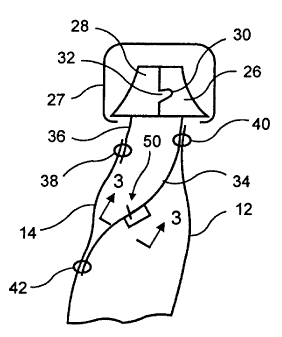
Figure 3 is a fragmentary sectional view taken along reference line 3-3 of
Figure 2.
Figure 4 is a fragmentary view depicting a first embodiment of a lime of
weakness
extending along a profile flange;
Figure 5 is a fragmentary view depicting a second embodiment of a line of
weakness
extending along a profile flange; and,
Fig. 6 is a figure similar to Figure 2 but with the line of weakness relocated
to a cusp
formed in the longer flange portion.
DETAILED DESCRIPTION OF THE PREFERRED EMBODIIvvIENT
Reference is now made to the drawings and to Figure 1 in particular wherein a
package
in accordance with the present invention is depicted comprising front and rear
walls 12, 14
joined at the bag bottom 16 and sides 18, 20. The bag top 22. is provided with
a zipper 24 which,
in turn may be provided with a slider 27 to facilitate opening and closing the
zipper. The zipper
24 consists of profiles 26,28 having mating interlocking members 30,32 which
interlock with
each other in a conventional manner.
Each of profiles 26, 28 further includes a downwardly extending flange 34. 36.
Flange 36
is secured to the bag rear wall 14 by a permanent seal 38 proximal the bag
top. Flange 34, which
is longer than flange 36, is secured to the bag front wall 12 by a permanent
seal 40 proximal the
bag top. Flange 34 is further secured by a permanent seal 42 to the bag rear
wall 14 by a
3


CA 02359397 2001-10-17
permanent seal 42 which is located below the seal 38. It should be appreciated
that the seals 38,
40 and 42 extend from side 18 to side 20 thereby securing the zipper 24 to the
bag 10 along the
width of the bag.
The bag walls 12, 14 are formed of a suitable plastic film material for the
product to be
contained within the package 10. The flange 34 may similarly be formed df a
laminate or
coextrusion or monolayer extrusion comprising a barrier layer 44 contained
within tie (or
adhesive) layers 46 and sealant layers 48. In this manner flange 34 and the
bag walls cooperate in
maintaining a barrier completely around the product to permit the hermetic
sealing of the
product within package 10. In addition, one of the internal or external layers
of flange 34 may
comprise a high temperature material to facilitate controlling the sealing of
the flange to the bag
walls as required. The sealant layers 48 facilitate sealing the flange to the
bag walls. The barrier
layer may provide resistance to moisture and/or gases such as oxygen, carbon
dioxide, nitrogen
and other gases from entering (or exiting) the package and permits the package
to be
hermetically sealed if required. The hermetic sealing of the package contents
is independent of
the zipper and will be maintained whether the zipper is opened or closed as
long as the bag walls
and flange 34 remain intact.
In accordance with the present invention, a line of weakness 50 is provided in
flange 34
extending along the flange parallel to interlocking member 32. The line of
weakness may
comprise a line of perforations 52 extending along the flange 34. To maintain
the barrier of
flange 34, the line of perforations is covered by a cap layer 54 in the manner
described in the
above mentioned patent 5,023,122. The cap layer having the required barrier
properties and
rendered frangible by a score line or appropriate grain orientation as
described in the above
referenced patent. Alternatively, the line of weakness SO may consist of a
score line 56 extending
4


CA 02359397 2001-10-17
towards, but not through the barrier layer of the flange. In either case, the
required barrier is
maintained notwithstanding the line of weakness of the flange 34.
In operation, after the zipper is initially opened by a consumer, the flange
34 is presented
before the consumer has access to the package contents. By bearing down on the
flange 34 or
simply separating the top ends of the bag, the line of weakness may be -
ruptured thereby
providing access to the contents. The intact flange 34 provides evidence to
the consumer that the
package has not been tampered with prior to the consumer's rupturing of the
weakened line.
To facilitate the consumer opening the package, the weakened line may be
provided
midway between the seal points 40, 42 of flange 34 or close to the seal point
42 to the bag walls.
In this regard, flange 34 may be formed into a generally V- shaped section as
shown in Fig. 6
with the line of weakness 50 in the cusp of the V. The package may then
readily be opened by
the consumer simply running a finger along the cusp to rupture the line of
weakness. However, if
the package is subjected to high internal pressure, the weakened line may be
moved toward seal
point 42 thereby providing a hinge effect enabling the weakened line to
withstand a greater
internal force.
Thus it will be seen that the aforementioned objects have been attained. It
should be
appreciated that modifications can be made to the disclosed embodiments of the
invention
without departing from the scope of the invention as set forth in the
following claims. For
example, the zipper may be designed for slider-less operation in which case
second, finger
flanges may be provided on the profiles above the interlocking members.
S

Representative Drawing
A single figure which represents the drawing illustrating the invention.
Administrative Status

For a clearer understanding of the status of the application/patent presented on this page, the site Disclaimer , as well as the definitions for Patent , Administrative Status , Maintenance Fee  and Payment History  should be consulted.

Administrative Status

Title Date
Forecasted Issue Date 2005-12-13
(22) Filed 2001-10-17
Examination Requested 2001-10-17
(41) Open to Public Inspection 2002-04-24
(45) Issued 2005-12-13
Deemed Expired 2014-10-17

Abandonment History

There is no abandonment history.

Payment History

Fee Type Anniversary Year Due Date Amount Paid Paid Date
Request for Examination $400.00 2001-10-17
Registration of a document - section 124 $100.00 2001-10-17
Application Fee $300.00 2001-10-17
Maintenance Fee - Application - New Act 2 2003-10-17 $100.00 2003-10-08
Maintenance Fee - Application - New Act 3 2004-10-18 $100.00 2004-10-08
Final Fee $300.00 2005-08-03
Maintenance Fee - Application - New Act 4 2005-10-17 $100.00 2005-10-03
Maintenance Fee - Patent - New Act 5 2006-10-17 $200.00 2006-10-02
Maintenance Fee - Patent - New Act 6 2007-10-17 $200.00 2007-10-01
Maintenance Fee - Patent - New Act 7 2008-10-17 $200.00 2008-09-30
Maintenance Fee - Patent - New Act 8 2009-10-19 $200.00 2009-10-01
Maintenance Fee - Patent - New Act 9 2010-10-18 $200.00 2010-09-30
Maintenance Fee - Patent - New Act 10 2011-10-17 $250.00 2011-09-30
Maintenance Fee - Patent - New Act 11 2012-10-17 $250.00 2012-10-01
Owners on Record

Note: Records showing the ownership history in alphabetical order.

Current Owners on Record
ILLINOIS TOOL WORKS INC.
Past Owners on Record
AUSNIT, STEVEN
BUCKMAN, THOMAS W.
SCHNEIDER, JOHN H.
Past Owners that do not appear in the "Owners on Record" listing will appear in other documentation within the application.
Documents

To view selected files, please enter reCAPTCHA code :


To view images, click a link in the Document Description column. To download the documents, select one or more checkboxes in the first column and then click the "Download Selected in PDF format (Zip Archive)" or the "Download Selected as Single PDF" button.

List of published and non-published patent-specific documents on the CPD .

If you have any difficulty accessing content, you can call the Client Service Centre at 1-866-997-1936 or send them an e-mail at CIPO Client Service Centre.


Document
Description 
Date
(yyyy-mm-dd) 
Number of pages   Size of Image (KB) 
Claims 2001-10-17 3 72
Representative Drawing 2002-01-31 1 6
Description 2001-10-17 5 214
Abstract 2001-10-17 1 20
Drawings 2001-10-17 2 26
Cover Page 2002-04-22 1 36
Description 2004-12-24 5 225
Claims 2004-12-24 3 85
Representative Drawing 2005-11-21 1 7
Cover Page 2005-11-21 1 36
Assignment 2001-10-17 7 268
Prosecution-Amendment 2004-06-28 3 89
Prosecution-Amendment 2004-12-24 8 386
Correspondence 2005-08-03 1 29