Note: Descriptions are shown in the official language in which they were submitted.
CA 02359822 2001-07-16
WO 00/42234 PCT/GB00/00013
MATERIAL FABRICATION
The present invention relates to a method of and an apparatus for depositing
material,
preferably a film, on a substrate and to a method of and an apparatus for
fabricating a
powder, preferably an ultrafme powder.
Material films, in particular ceramic films, have wide ranging structural and
functional
applications. These different applications often require films of different
thickness,
but there is no single commercially cost-effective film or coating deposition
technique
for depositing both thin films, typically films having a thickness of less
than 1 Vim, and
thick films, typically films having a thickness greater than 10 Vim.
Vapour processing techniques, including chemical vapour deposition (CVD) and
physical vapour deposition (PVD), have been used to fabricate thin films, but,
because
of the slow deposition rate and expensive equipment, are not suited to the
deposition of
thick films of large area. Moreover, the coating of substrates of complex
shape is
particularly difficult using a PVD technique.
Sol-gel processing techniques have also been used to deposit thin films, but,
while thin
films can be achieved in a single coating run, thicker films provided by a
single
coating are cracked and thus thick solid films have to be built up by
performing a
plurality of successive coating runs.
A novel deposition technique, referred to as electrostatic spray assisted
vapour
deposition (ESAVD) and disclosed in WO-A-97/21848, has also been used
ti
particularly to deposit thin films. In this ESAVD technique, an aerosol is
electrostatically generated from a nozzle unit and a temperature gradient and
electric
field are provided between the substrate and the nozzle unit such that the
aerosol
droplets undergo combustion and/or chemical reaction in the vapour phase clds~
to the
surface of the substrate. This deposition technique is capable of producing
solid films
which exhibit excellent substrate adhesion, but does have limitations as a
consequence
of electrostatically generating the aerosol, for example, with regard to the
nature of the
CA 02359822 2001-07-16
WO 00/42234 PCT/GB00/00013
2
utilisable precursor solutions. the deposition rate and the droplet size
distribution of the
aerosols.
Spray pyrolysis, where a film is deposited by delivering an aerosol generated
by
ultrasonic atomisation to a heated substrate, has been used to deposit both
thin and
thick films as disclosed, for example, in EP-A-0103505 and GB-A-1362803, but
the
deposition efficiency is usually very low because of the very high loss of the
aerosol to
the environment, which loss is unacceptable both for environmental reasons and
cost
reasons where the precursor materials can be expensive and the deposition rate
is very
low. Furthermore, the deposition of very thick films, typically films having a
thickness of greater than 150 Vim, by spray pyrolysis is difficult. In
published articles
entitled "Corona Spray Pyrolysis" Thin Solid Films, 121 (1984), pages 267 to
274 and
"Properties of Thin In203 and Sn02 Films Prepared by Corona Spray Pyrolysis
and a
Discussion of the Spray Pyrolysis Process" Thin Solid Films, 121 (1984), pages
275 to
282, the deposition of thin films of doped In203 and Sn02 by corona spray
pyrolysis
with a claimed deposition efficiency of up to 80 % has been discussed, but
this
deposition technique essentially requires the use of an organic precursor
solution, the
delivery of the aerosol vertically downwardly so as to utilise the
gravitational effect on
the aerosol droplets, and a specific electrode configuration comprising two
electrodes
each disposed at an angle of from 40 to 45° relative to the vertically
downward flow
path of the aerosol.
It is an aim of the present invention to provide an improved method of and
apparatus
for depositing material, preferably one of thin or thick films, on a
substrate, referred to
as electrostatic assisted aerosol jet deposition (EAAJD), which in particular
is low cost
and exhibits a high deposition efficiency, and an improved method of and
apparatus
for fabricating a powder, preferably an ultrafine powder.
Accordingly, the ~ present invention provides a method of depositing material,
preferably a film, on a substrate, comprising the steps of: providing a
substrate; heating
the substrate; generating an aerosol comprising droplets of a material
solution;
providing a nozzle unit for delivering the aerosol to the substrate, the
nozzle unit
CA 02359822 2001-07-16
WO 00/42234 PCT/GB00/00013
J
including at least one outlet through which a directed flow of the aerosol is
delivered
and at least one electrode; charging the aerosol droplets with a positive or
negative
charge; providing a flow of the aerosol through the nozzle unit so as to
deliver a
directed flow of the aerosol from the at least one outlet; and generating an
electric field
between the substrate and the at least one electrode such that the directed
aerosol flow
is attracted towards the substrate.
Preferably, the substrate is heated to a temperature of less than about 1050
°C, more
preferably less than about 800 °C.
Preferably, the substrate is heated during deposition.
More preferably, the thermal environment is such as to maintain a decreasing
temperature gradient in a direction away from the substrate towards the nozzle
unit.
In one embodiment the material solution is an aqueous solution.
In another embodiment the material solution is a non-aqueous solution.
Preferred non-
aqueous solvents include acetylacetone, methanol and 2-methoxyethanol.
In one embodiment the aerosol droplets are at least partially charged prior to
exiting
the at least one outlet.
In another embodiment the aerosol droplets are charged prior to exiting the at
least one
outlet.
In a further embodiment the aerosol droplets are at least partially charged
after exiting
the at least one outlet.
Preferably, the aerosol droplets are charged by the at least one electrode.
Preferably, the at least one electrode is disposed at least partially in each
aerosol flow.
CA 02359822 2001-07-16
WO 00/42234 PCT/GB00/00013
4
Preferably, the at least one electrode extends upstream of the at least one
outlet.
Preferably, the at least one electrode comprises an elongate element.
Preferably, the distal end of the at least one electrode is located at
substantially the
centre of the at least one outlet.
In one embodiment the distal end of the at least one electrode includes a
single tip.
In another embodiment the distal end of the at least one electrode includes a
plurality
of tips.
Preferably, the nozzle unit includes a tubular section upstream of each
outlet.
More preferably, the tubular section is an elongate section.
More preferably, the tubular section is a linear section.
More preferably, the tubular section is substantially cylindrical.
More preferably, the at least one electrode extends substantially entirely
through the
associated tubular section.
More preferably, the at least one electrode extends substantially along the
central axis
of the associated tubular section.
More preferably, at least the inner surface of the tubular section is composed
of an
insulating material.
In one embodiment the aerosol flow is provided by entraining the aerosol in a
flow of
a carrier gas fed to the nozzle unit.
CA 02359822 2001-07-16
WO 00/42234 PCT/GB00/00013
In another embodiment the aerosol flow is provided by applying a reduced
pressure to
the at least one outlet so as to entrain the aerosol in a flow of a carrier
gas drawn
through the nozzle unit.
5
In one embodiment the carrier gas is a gas reactive to the material solution.
In another embodiment the carrier gas is a gas non-reactive to the material
solution.
Preferably, the flow of the carrier gas is provided, typically by controlling
the flow
rate, temperature and/or direction, such as to maintain the decreasing
temperature
gradient.
Preferably, the aerosol is delivered to the substrate such as to achieve a
film growth
rate of at least 0.2 ~m per minute.
More preferably, the aerosol is delivered to the substrate such as to achieve
a film
growth rate of at least 1 ~.m per minute.
Still more preferably, the aerosol is delivered to the substrate such as to
achieve a film
growth rate of at least 2 p.m per minute.
Preferably, the flow rate through the at least one outlet is at least 5 ml per
minute,
more preferably at least 50 ml per minute.
Preferably, the nozzle unit is configured such that the aerosol flow from the
at least
one outlet is directed upwards, more preferably substantially vertically
upwards.
Preferably, the nozzle unit includes a perforated member upstream of the at
least one
outlet. In a preferred embodiment the perforated member comprises a mesh.
CA 02359822 2001-07-16
WO 00/42234 PCT/GB00/00013
6
Preferably, the applied voltage is less than about 35 kV, more preferably less
than
about 20 kV.
Preferably, the distance between the at least one outlet and the substrate is
less than
about 100 mm, more preferably less than about 50 mm.
In one embodiment the substrate is held stationary relative to the nozzle
unit.
In another embodiment the method further comprises the step of moving the
nozzle
unit relative to the substrate.
Preferably, the substrate is rotated, tilted and/or translated relative to the
nozzle unit.
In one embodiment deposition is performed at atmospheric pressure.
In another embodiment deposition is performed below atmospheric pressure.
In a further embodiment deposition is performed above atmospheric pressure.
Preferably, the method further comprises the step of varying one or both of
the
composition and concentration of the material solution during deposition.
Preferably, the method further comprises the step of reversing the polarity
between the
substrate and the at least one electrode at intervals during deposition.
Preferably, the method further comprises the step of locally heating at least
one area of
the substrate.
Preferably, the method further comprises the step of one or both of
electrically or
magnetically steering the aerosol droplets in transit from the nozzle unit to
the
substrate.
CA 02359822 2001-07-16
WO 00/42234 PCT/GB00/00013
7
Preferably, the film is one or both of a structural film or a functional film,
typically,
for use in engineering and medical applications.
Preferably, the film is one of a dense or porous film.
Preferably, the film is one of an amorphous or crystalline film.
Preferably, the film is one of a simple film, a doped film or a mufti-
component film;
typically, non-oxide or oxide films.
Preferably, the film is a composite film.
Preferably, the film is a compositionally-graded film.
Preferably, the film is a mufti-layered film.
In one embodiment the film is an inorganic film.
Preferably, the film is a ceramic film, more preferably an electroceramic
film.
In another embodiment the film is an organic film.
Preferably, the film is a polymer film.
In a further embodiment the film is a hybrid film, such as an
organic/inorganic film.
The present invention also provides an apparatus for depositing material,
preferably a
film, on a substrate, comprising: a substrate holder for holding a substrate;
a heater for
heating the substrate; an aerosol generator for generating an aerosol
comprising
droplets of a material solution; a charge applicator for applying a positive
or negative
charge to the aerosol droplets; a nozzle unit in communication with the
aerosol
generator for delivering the aerosol to the substrate, the nozzle unit
including at least
CA 02359822 2001-07-16
WO 00/42234 PCT/GB00/00013
8
one outlet through which a directed flow of the aerosol is in use delivered
and at least
one electrode; and a high voltage supply for generating an electric field
between the
substrate and the at least one electrode such that the directed aerosol flow
is in use
attracted towards the substrate.
Preferably, the apparatus is configured to maintain a decreasing temperature
gradient
in a direction away from the substrate towards the nozzle unit.
Preferably, the at least one electrode extends upstream of the at least one
outlet.
Preferably, the at least one electrode comprises an elongate element.
Preferably, the distal end of the at least one electrode is located at
substantially the
centre of the at least one outlet.
In one embodiment the distal end of the at least one electrode includes a
single tip.
In another embodiment the distal end of the at least one electrode includes a
plurality
of tips.
Preferably, the nozzle unit includes a tubular section upstream of each
outlet.
More preferably, the tubular section is an elongate section.
More preferably, the tubular section is a linear section.
More preferably, the tubular section is substantially cylindrical.
More preferably, the at least one electrode extends substantially entirely
through the
associated tubular section.
CA 02359822 2001-07-16
WO 00/42234 PCT/GB00/00013
9
More preferably, the at least one electrode extends substantially along the
central axis
of the associated tubular section.
More preferably, at least the inner surface of the tubular section is composed
of an
insulating material.
Preferably, the apparatus further comprises a gas supply unit in communication
with
the aerosol generator for supplying a flow of a carrier gas for entraining the
aerosol
and delivering the same through the nozzle unit.
Preferably, the at least one outlet is directed upwards, more preferably
substantially
vertically upwards.
Preferably, the distance between the at least one outlet and the substrate is
less than
1 ~ about 100 mm, more preferably less than about 50 mm.
In one embodiment the nozzle unit and the substrate holder are held in fixed
relation.
In another embodiment the nozzle unit and the substrate holder are configured
so as to
be movable relative to one another.
More preferably, the substrate holder is rotatable, tiltable and/or
translatable relative to
the nozzle unit.
2~ Preferably, the apparatus further comprises a chamber for enclosing the
substrate
holder.
More preferably, the apparatus further comprises a further gas supply unit in
communication with the chamber for separately delivering a further gas to the
same.
Preferably, the nozzle unit includes a perforated member upstream of the at
least one
outlet. In one embodiment the perforated member comprises a mesh.
CA 02359822 2001-07-16
WO 00/42234 PCT/GB00/00013
The present invention further provides a method of fabricating a powder,
preferably an
ultrafine powder, comprising the steps of: providing a heated zone; generating
an
aerosol comprising droplets of a material solution; providing a nozzle unit
for
5 delivering the aerosol to the heated zone, the nozzle unit including at
least one outlet
through which a directed flow of the aerosol is delivered and at least one
electrode;
charging the aerosol droplets with a positive or negative charge; providing a
flow of
the aerosol through the nozzle unit so as to deliver a directed flow of the
aerosol from
the at least one outlet; and generating an electric field between the heated
zone and the
10 at least one electrode such that the directed aerosol flow is attracted
towards the heated
zone where the aerosol droplets react homogeneously in the gas phase to form a
powder.
The present invention still further provides an apparatus for fabricating a
powder,
preferably an ultrafine powder, comprising: a heater for providing a heated
zone; an
aerosol generator for generating an aerosol comprising droplets of a material
solution;
a charge applicator for applying a positive or negative charge to the aerosol
droplets; a
nozzle unit in communication with the aerosol generator for delivering the
aerosol to
the heated zone, the nozzle unit including at least one outlet through which a
directed
flow of the aerosol is in use delivered and at least one electrode; and a high
voltage
supply for generating an electric field between the heated zone and the at
least one
electrode such that the directed aerosol flow is in use attracted towards the
heated zone
where the aerosol droplets react homogeneously in the gas phase to form a
powder.
The present invention is able, unlike the ESAVD technique disclosed in WO-A-
97/21848, to utilise both aqueous and non-aqueous precursor solutions and
particularly
colloidal sol solutions, and allows much higher deposition rates, typically at
least twice
the rate possible using the ESAVD technique. Further, unlike the deposition
technique
disclosed in EP-A-0103505, crystalline, in particular dense, films can be
produced in a
single run without requiring a post-deposition heat treatment. Still further,
unlike the
corona spray pyrolysis deposition technique mentioned hereinabove, an organic
precursor solution is not essentially required and in delivering the aerosol
upwardly,
CA 02359822 2001-07-16
WO 00/42234 PCT/GB00/00013
preferably substantially vertically upwardly, to a downwardly-facing
substrate, a more
stable thermal environment can be maintained at the surface of the substrate
so as to
allow for a more precise control of the film deposition and hence provide an
improved
film.
In preferred embodiments of the present invention a deposition efficiency of
at least 90
has been obtained, which enhanced deposition efficiency reduces the product
cost
and minimises the loss of the possibly harmful precursor materials to the
environment.
Preferred embodiments of the present invention will now be described
hereinbelow by
way of example only with reference to the accompanying drawings, in which:
Figure 1 schematically illustrates a film deposition apparatus in accordance
with a first
embodiment of the present invention;
Figure 2 illustrates a sectional view of the outlet end of the nozzle unit of
the film
deposition apparatus of Figure 1;
Figure 3 illustrates a sectional view of the inlet end of the nozzle unit of
the film
deposition apparatus of Figure 1;
Figure 4 illustrates an end view of the inlet end of the nozzle unit of the
film
deposition apparatus of Figure 1;
Figure 5 illustrates a sectional view of the outlet end of a modified nozzle
unit for the
film deposition apparatus of Figure 1;
Figure 6 schematically illustrates a film deposition apparatus in accordance
with a
second embodiment of the present invention;
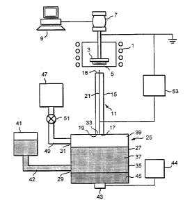
Figure 7 schematically illustrates a film deposition apparatus in accordance
with a
third embodiment of the present invention;
CA 02359822 2001-07-16
WO 00/42234 PCT/GB00/00013
12
Figure 8 illustrates a sectional view of the outlet end of a modified nozzle
unit for the
film deposition apparatus of Figure 7;
~ Figure 9 illustrates an X-ray diffraction pattern of a BaZr03 film as
fabricated by
Example 1;
Figures 10(a) and (b) illustrate surface and cross-sectional SEM micrographs
of a CdS
film as fabricated by Example 2; and
Figures 11(a) and (b) illustrate surface and cross-sectional SEM micrographs
of a
porous Si02 film as fabricated by Example 3.
Figure 1 illustrates a film deposition apparatus in accordance with a first
embodiment
of the present invention.
The film deposition apparatus comprises a heater l, in this embodiment a tube
furnace,
for providing a heated zone, and a substrate holder 3 for holding a substrate
5 in the
heated zone such as to provide a decreasing temperature gradient in a
direction away
from the surface of the substrate 5 to be coated. The substrate holder 3 is
movably
disposed relative to the heater 1 such as to be able to alter both the
temperature and the
temperature gradient at the surface of the substrate 5 to be coated. In this
embodiment
the substrate holder 3 is also rotatably disposed about the longitudinal axis
of the
heater 1 such as to present a moving surface of the substrate 5 to be coated
to one end
of the heater 1 and thereby enable more uniform film deposition.
The film deposition apparatus further comprises a motor unit 7 which is
coupled to the
substrate holder 3 such as on operation to rotate the same, and a computer 9
for
controlling the operation of the motor unit 7.
Referring particularly to Figures 2 to 4, the film deposition apparatus
further comprises
a nozzle unit 11 for delivering a directed aerosol flow to the substrate 5 to
be coated.
CA 02359822 2001-07-16
WO 00/42234 PCT/GB00/00013
13
The nozzle unit 11 comprises a tubular section 1 ~, in this embodiment an
elongate
cylindrical section, which includes an inlet port 17 at one end thereof
through which an
aerosol flow is introduced and an outlet port 18 at the other end thereof
through which
a directed aerosol flow is delivered to the substrate ~ to be coated, the
internal
geometry of the tubular section 15 being such as to confer directionality to
the aerosol
flow. The distance between the outlet port 18 of the nozzle unit 11 and the
substrate 5
is preferably less than 100 mm, more preferably less than 50 mm, and still
more
preferably not more than 20 mm. The tubular section 15 is formed of a non-
conductive, insulating material, such as a ceramic, glass or quartz, which can
withstand the high temperatures developed by the heater 1. The nozzle unit 11
further
comprises a perforated member 19 disposed at the inlet port 17 of the tubular
section
1 ~, with the flow path through the tubular section 1 S being through the
perforations 20
in the perforated member 19. The perforated member 19 is a conductive member,
preferably formed of aluminium, stainless steel or an indium-tin oxide coated
plate.
The nozzle unit 11 further comprises an electrode 21, in this embodiment an
elongate
element, such as a wire, having a single sharp-pointed tip, which is attached
to the
perforated member 19 and extends co-axially through the length of the tubular
section
15, in this embodiment with the tip thereof located downstream of the outlet
port 18.
The electrode 21 can be formed of any conductive material, but is preferably
formed of
aluminium, stainless steel or tungsten. In a modified nozzle unit 11, as
illustrated in
Figure 5, the electrode 21 can be mufti-tipped.
The film deposition apparatus further comprises an aerosol generator 25 for
providing
a flow of an aerosol to the inlet port 17 of the nozzle unit 11. The aerosol
generator 25
comprises a chamber 27 which includes first and second inlet ports 29, 31 and
an
outlet port 33 connected to the inlet port 17 of the nozzle unit 11, and
defines a
reservoir 35 for containing a precursor solution 37 to be aerosolised and a
head space
39 in which an aerosol collects when generated. The aerosol generator 25
further
comprises a liquid level controller 41 connected by a line 42 to the first
inlet port 29 of
the chamber 27 for maintaining a constant volume of the precursor solution 37
in the
reservoir 35. The aerosol generator 25 further comprises a piezoelectric
transducer 43
which is driven by a power supply 44 and is in communication with the
reservoir 35
CA 02359822 2001-07-16
WO 00/42234 PCT/GB00/00013
14
through a transfer medium 4~, such as water, contained separately from the
precursor
solution 37 such that on operation of the piezoelectric transducer 43 the
liquid
precursor 37 is ultrasonically vibrated to generate an aerosol in the head
space 39. In a
preferred embodiment the piezoelectric transducer 43 is operated at a
frequency in the
range of from 1.7 to 3 MHz, thereby allowing aerosols to be achieved at a rate
of
greater than 5 ml per minute with a droplet size of less than 2 qm and a
narrow size
distribution. The aerosol generator 25 further comprises a gas supply unit 47
connected through a delivery line 49 to the second inlet port 31 of the
chamber 27 for
providing a flow of a carrier gas through the chamber 27 such as to entrain
the aerosol
in the head space 39 and transport the same to the substrate 5 through the
nozzle unit
11. In this embodiment the delivery line 49 includes a flow regulating valve
51 for
controlling the flow rate of aerosol to the substrate 5. Preferably, the
carrier gas
comprises at least one of air, Ar, HZS, N2, NH3 and O2. In an alternative
embodiment,
instead of or in addition to the gas supply unit 47, pressure reducing means,
such as a
vacuum pump, could be provided for applying a reduced pressure at the outlet
port 18
of the tubular section 15 so as to draw the aerosol as a flow therethrough.
The film deposition apparatus further comprises a high voltage d.c. supply 53
connected between the electrode 21 and the substrate 5 such as to establish an
electric
field between the same, which electric field charges the aerosol droplets on
passing the
electrode 21 and causes the charged droplets to be attracted to the substrate
5 on
exiting the outlet port 18 of the nozzle unit 11. In a preferred embodiment
the voltage
applied between the electrode 21 and the substrate 5 is from 10 to 30 kV.
In use, the aerosol generator 25 is operated to provide a gas flow entraining
aerosol
droplets through the nozzle unit 11, which flow through the nozzle unit 11
provides a
directed aerosol flow from the outlet port 18 of the tubular section 15 and
results in
charging of the aerosol droplets on passing the electrode 21. On exiting the
outlet port
18 of the nozzle unit 11 the charged aerosol droplets are attracted to the
substrate 5,
with the flow rate of the aerosol, and the temperature and temperature
gradient at the
surface of the substrate 5 being optimised to achieve the desired film
properties,
typically one of a porous or dense solid film. In preferred embodiments the
thermal
CA 02359822 2001-07-16
WO 00/42234 PCT/GB00/00013
environment and the velocity of the directed aerosol flow can be configured
such that
the aerosol droplets are vaporised/decomposed close to the surface of the
substrate ~ or
impact the surface of the substrate 5 prior to vaporisation/decomposition.
This process
is continued until a film of the required thickness has been achieved on the
substrate 5.
Figure 6 illustrates a film deposition apparatus in accordance with a second
embodiment of the present invention which finds particular application in the
deposition of films on large area substrates.
10 The film deposition apparatus comprises a heater 101, in this embodiment a
resistance
heater, and a substrate holder 103 for holding a substrate 105 mounted to the
heater
101 such as to provide a decreasing temperature gradient in a direction away
from the
surface of the substrate 5 to be coated. In this embodiment the substrate
holder 103
includes an insulating member 106 which extends forwardly about the periphery
of the
15 substrate 10~ and is configured to maintain a uniform temperature and
temperature
gradient at the surface of the substrate 105 to be coated. Although in this
embodiment
the substrate 105 is heated by contact heating, here resistance heating, non-
contact
heating, such as by way of an infra-red lamp, could be employed to heat the
substrate
105.
The film deposition apparatus further comprises a nozzle unit 111 for
delivering a
directed aerosol flow to the substrate 105 to be coated. The nozzle unit 111
is of the
same kind as employed in the film deposition apparatus of the above-described
first
embodiment, with corresponding reference signs being used to designate like
parts.
The nozzle unit 111 comprises a tubular section 115, in this embodiment an
elongate
cylindrical section, which includes an inlet port 117 at one end thereof
through which
an aerosol flow is introduced and an outlet port 118 at the other end thereof
through
which a directed aerosol flow is delivered to the substrate 105 to be coated,
the internal
geometry of the tubular section 115 being such as to confer directionality to
the
aerosol flow. The distance between the outlet port 118 of the nozzle unit 111
and the
substrate 105 is preferably less than 100 mm, more preferably less than 50 mm,
and
still more preferably not more than 20 mm. The tubular section 115 is formed
of a
CA 02359822 2001-07-16
WO 00/42234 PCT/GB00/00013
16
non-conductive, insulating material. such as a ceramic, glass or quartz, which
can
withstand the high temperatures developed by the heater 101. The nozzle unit
111
further comprises a perforated member 119 disposed at the inlet port 117 of
the tubular
section 115, with the flow path through the tubular section 115 being through
the
perforations 120 in the perforated member 119. The perforated member 119 is a
conductive member, preferably formed of aluminium, stainless steel, tungsten
or an
indium-tin oxide coated plate. The nozzle unit 111 further comprises an
electrode 121,
in this embodiment an elongate element, such as a wire, having a single sharp-
pointed
tip, which is attached to the perforated member 119 and extends co-axially
through the
length of the tubular section 115. in this embodiment with the tip thereof
located
downstream of the outlet port 118. The electrode 121 can be formed of any
conductive material, but is preferably formed of aluminium, stainless steel or
tungsten.
In a modified nozzle unit 111, as illustrated in Figure 5, the electrode 121
can be
mufti-tipped.
The film deposition apparatus further comprises an aerosol generator 125 for
providing
a flow of an aerosol to the inlet port 117 of the nozzle unit 111. The aerosol
generator
125 comprises a chamber 127 which includes first and second inlet ports 129,
131 and
an outlet port 133 connected by a flexible tubular section 134 to the inlet
port 117 of
the nozzle unit 111, and defines a reservoir 135 for containing a precursor
solution 137
to be aerosolised and a head space 139 in which an aerosol collects when
generated.
The aerosol generator 125 further comprises a liquid level controller 141
connected by
a line 142 to the first inlet port 129 of the chamber 127 for maintaining a
constant
volume of the precursor solution 137 in the reservoir 13~. The aerosol
generator 125
further comprises a piezoelectric transducer 143 which is driven by a power
supply
144 and is in communication with the reservoir 135 through a transfer medium
145,
such as water, contained separately from the precursor solution 137 such that
on
operation of the piezoelectric transducer 143 the precursor solution 137 is
ultrasonically vibrated to generate an aerosol in the head space 139. The
aerosol
generator 125 further comprises a gas supply unit 147 connected through a
delivery
line 149 to the second inlet port 131 of the chamber 127 for providing a flow
of a
carrier gas through the chamber 127 such as to entrain the aerosol in the head
space
CA 02359822 2001-07-16
WO 00/42234 PCT/GB00/00013
17
139 and transport the same to the substrate 105 through the nozzle unit 111.
In this
embodiment the delivery line 149 includes a flow regulating valve 151 for
controlling
the flow rate of aerosol delivered to the substrate 105. Preferably, the
carrier gas
comprises at least one of air. Ar, HAS, N~, NH3 and O2. In an alternative
embodiment,
instead of or in addition to the gas supply unit 147, pressure reducing means,
such as a
vacuum pump, could be provided for applying a reduced pressure at the outlet
port 118
of the tubular section 11 ~ so as to draw the aerosol as a flow therethrough.
The film deposition apparatus further comprises a high voltage d.c. supply 153
connected between the electrode 121 and the substrate 105 such as to establish
an
electric field between the same, which electric field charges the aerosol
droplets on
passing the electrode 121 and causes the charged droplets to be attracted to
the
substrate 105 on exiting the outlet port 118 of the nozzle unit 111. In a
preferred
embodiment the voltage applied between the electrode 121 and the substrate 105
is
from 10 to 30 kV.
The film deposition apparatus further comprises an X-Y-Z table 155 connected
to the
nozzle unit 111 so as to allow for movement of the nozzle unit 111 relative to
the
substrate 105 in coating substrates of large area and non-planar shape, and a
computer
157 for controlling the X-Y-Z table 155. Where the substrate 105 is planar,
the X-Y-Z
table 155 could be replaced by an X-Y table.
In use, the aerosol generator 125 is operated to provide a gas flow entraining
aerosol
droplets through the nozzle unit 11 l, which flow through the nozzle unit 111
provides
a directed aerosol flow from the outlet port 118 of the tubular section 115
and results
in charging of the aerosol droplets on passing the electrode 121. On exiting
the outlet
port 118 of the nozzle unit 111 the charged aerosol droplets are attracted to
the
substrate 105, with the flow rate of the aerosol, and the temperature and
temperature
gradient at the surface of the substrate 105 being optimised to achieve the
desired film
properties, typically one of a porous or dense solid film. In preferred
embodiments the
thermal environment and the velocity of the directed aerosol flow can be
configured
such that the aerosol droplets are vaporised/decomposed close to the surface
of the
CA 02359822 2001-07-16
WO 00/42234 PCT/GB00/00013
18
substrate 10~ or impact the surface of the substrate 105 prior to
vaporisation/decomposition. This process is continued until a film of the
required
thickness has been achieved on the substrate 105.
Figure 7 illustrates a film deposition apparatus in accordance with a third
embodiment
of the present invention which finds particular application in the deposition
of films
onto three-dimensional substrates of complex shape, such as tubular sections.
The film deposition apparatus comprises a heater 201 which includes an
enclosed
deposition chamber 202, in this embodiment an enclosed tube furnace, in which
is
provided a heated zone, and a substrate holder 203 for holding a substrate 20~
in the
heating chamber 202. The substrate holder 203 is rotatably disposed, in this
embodiment about the longitudinal axis of the heating chamber 202, within the
heater
201 such as to allow for the presentation of the entire surface of the
substrate 205 to be
coated to an aerosol flow. The heating chamber 202 includes an inlet port 206
through
which a gas can be introduced thereinto, an outlet port 207 which acts as an
exhaust,
and a radial opening 208 through which a nozzle unit 211 extends for
delivering an
aerosol thereinto. In this embodiment the outlet port 207 is connected to a
exhaust line
209 which includes a flow regulating valve 210 for regulating the flow rate
from the
heating chamber 202.
The film deposition apparatus further comprises a nozzle unit 211 which
extends
through the radial opening 208 in the deposition chamber 202 for delivering a
directed
aerosol flow to the substrate 20~ to be coated. This nozzle unit 211 is of a
similar
construction to that employed in the film deposition apparatus of the above-
described
first embodiment, with corresponding reference signs being used to designate
like
parts. The nozzle unit 211 comprises a tubular section 215, in this embodiment
an
elongate cylindrical section with a inwardly-tapered outlet end, which
includes an inlet
port 217 at one end thereof through which an aerosol flow is introduced and an
outlet
port 218 at the other end thereof through which a directed aerosol flow is
delivered to
the substrate 205 to be coated, the internal geometry of the tubular section
215 being
such as to confer directionality to the aerosol flow. The tubular section 215
is
CA 02359822 2001-07-16
WO 00/42234 PCT/GB00/00013
19
preferably formed of a non-conductive, insulating material, such as a ceramic,
glass or
quartz, which can withstand the high temperatures developed by the heater 201.
The
nozzle unit 211 further comprises an electrode 221, in this embodiment an
elongate
element, such as a wire, having a single sharp-pointed tip, which extends co-
axially
through a length of the tubular section 215, in this embodiment with the tip
thereof
located upstream of the outlet port 218, that is, within the tubular section
215. The
electrode 221 can be formed of any conductive material, but is preferably
formed of
aluminium, stainless steel or tungsten. In a modified nozzle unit 211, as
illustrated in
Figure 5, the electrode 221 can be mufti-tipped.
The film deposition apparatus further comprises an aerosol generator 225 for
providing
a flow of an aerosol to the inlet port 217 of the nozzle unit 211. The aerosol
generator
225 comprises a chamber 227 which includes first and second inlet ports 229,
231 and
an outlet port 233 connected by a flexible tubular section 234 to the inlet
port 217 of
the nozzle unit 211, and defines a reservoir 235 for containing a precursor
solution 137
to be aerosolised and a head space 239 in which an aerosol collects when
generated.
The aerosol generator 225 further comprises a liquid level controller 241
connected by
a line 242 to the first inlet port 229 of the chamber 227 for maintaining a
constant
volume of the precursor solution 237 in the reservoir 235. The aerosol
generator 225
further comprises a piezoelectric transducer 243 which is driven by a power
supply
244 and is in communication with the reservoir 235 through a transfer medium
245,
such as water, contained separately from the precursor solution 237 such that
on
operation of the piezoelectric transducer 243 the liquid precursor 237 is
ultrasonically
vibrated to generate an aerosol in the head space 239. The aerosol generator
225
further comprises a first gas supply unit 247 connected through a delivery
line 249 to
the second inlet port 231 of the chamber 227 for providing a flow of a carrier
gas
through the chamber 227 such as to entrain the aerosol in the head space 239
and
transport the same to the substrate 205 through the nozzle unit 211. In this
embodiment the first gas supply unit 247 includes a temperature conditioner
for
controlling the temperature of the delivered gas, the importance of which will
become
apparent hereinbelow. Further, in this embodiment the delivery line 249
includes a
flow regulating valve 251 for controlling the gas flow rate and hence the flow
rate of
CA 02359822 2001-07-16
WO 00/42234 PCT/GB00/00013
aerosol delivered to the substrate 205. Preferably, the carrier gas comprises
at least
one of air, Ar, HZS, N~, NH; and O~. In an alternative embodiment, instead of
or in
addition to the first gas supply unit 247, pressure reducing means, such as a
vacuum
pump, could be provided for applying a reduced pressure at the outlet port 207
of the
5 heating chamber 202 so as to draw the aerosol as a flow through the nozzle
unit 211.
The film deposition apparatus further comprises a high voltage d.c. supply 253
connected between the electrode 221 and the substrate 205 such as to establish
an
electric field between the same, which electric field charges the aerosol
droplets on
10 passing the electrode 221 and causes the charged droplets to be attracted
to the
substrate 205 on exiting the outlet port 218 of the nozzle unit 211. In a
preferred
embodiment the voltage applied between the electrode 221 and the substrate 205
is
from 10 to 30 kV. In this embodiment the film deposition apparatus further
comprises
a plurality of deflector plates 254 disposed within the deposition chamber 202
about
15 the location of the substrate 205, which deflector plates 254 are connected
to the high
voltage d.c. supply 253 such as to have the same polarity as the electrode 221
and
hence the charged aerosol droplets and act to deflect the aerosol droplets
towards the
substrate 205, thereby minimising the deposition of material on the internal
walls of
the deposition chamber 202.
The film deposition apparatus further comprises a second gas supply unit 255
connected by a delivery line 256 to the inlet port 206 of the deposition
chamber 202
for providing a controlled environment in the deposition chamber 202.
Preferably, the
gas is an inert gas, such as argon or nitrogen. In this embodiment the
delivery line 256
includes a flow regulating valve 257 for controlling the flow rate of gas
delivered to
the deposition chamber 202.
The film deposition apparatus further comprises a first motor unit 258
connected to the
substrate holder 203 so as to provide for movement of the substrate holder 203
and
hence the substrate 205, in this embodiment by rotation and axial movement, in
the
deposition chamber 202 relative to the outlet port 218 of the nozzle unit 21
l, a second
motor unit 259 connected to the nozzle unit 211 so as to provide for movement
of the
CA 02359822 2001-07-16
WO 00/42234 PCT/GB00/00013
21
nozzle unit 21 l, in this embodiment radial movement, in the deposition
chamber 202
relative to the substrate holder 203 and hence the substrate 205, and a
computer 261
for controlling the operation of the first and second motor units 258, 259.
The distance
between the outlet port 218 of the nozzle unit 211 and the surface of the
substrate 205
being coated is preferably maintained at less than 100 mm. more preferably
less than
50 mm, and still more preferably not more than 20 mm.
In use, the aerosol generator 225 is operated to provide a gas flow entraining
aerosol
droplets through the nozzle unit 21 l, which flow through the nozzle unit 211
provides
a directed aerosol flow from the outlet port 218 of the tubular section 215
and results
in charging of the aerosol droplets on passing the electrode 221. On exiting
the outlet
port 218 of the nozzle unit 211 the charged aerosol droplets are attracted to
the
substrate 205, with the flow rate of the aerosol, and the temperature and
temperature
gradient at the surface of the substrate 205 being optimised to achieve the
desired film
properties, typically one of a porous or dense solid film. In this embodiment
a
temperature gradient is maintained at the surface of the substrate 205 by
controlling
both the temperature and the flow rate of the carrier gas supplied by the
first gas
supply unit 247. In preferred embodiments the thermal environment and the
velocity
of the directed aerosol flow can be configured such that the aerosol droplets
are
vaporised/decomposed close to the surface of the substrate 205 or impact the
surface
of the substrate 205 prior to vaporisation/decomposition. With the continued
relative
movement of the substrate 205 and the nozzle unit 21 l, this process is
continued until
a film of the required thickness has been achieved over the surface of the
substrate
205.
In one modification to the above-described third embodiment, as illustrated in
Figure
8, the nozzle unit 211 can include a cooling jacket 261 located about the
tubular
section 215 for cooling the internal volume of the tubular section 215 through
which
the aerosol is delivered. The cooling jacket 261 includes a cavity 263 through
which a
cooling medium, typically a liquid, such as oil or water, is continuously
circulated.
The nozzle unit 211 can also include a secondary electrode 265, in this
embodiment an
annular element located about the longitudinal axis of the primary electrode
221,
CA 02359822 2001-07-16
WO 00/42234 PCT/GB00/00013
22
disposed downstream of the primary electrode 221 which acts to focus and
accelerate
the aerosol droplets towards the substrate 205.
In another modification to the above-described third embodiment, the apparatus
can be
set up to fabricate powders, preferably ultrafme powders. In this
modification, the
substrate holder 203 and the deflector plates 254 are removed and replaced by
a plate
which is disposed substantially opposite to the outlet port 218 of the nozzle
unit 211
and connected to the high voltage d.c. supply 253 such that an electric field
is
developed between the plate and the electrode 221. In use, with the thermal
environment in the heated zone configured appropriately, the aerosol droplets
exiting
the nozzle unit 211 react homogeneously in the gas phase to provide a powder
which
collects in the heating chamber 202. By controlling the size of the aerosol
droplets
ultrafine powders can be fabricated.
The present invention will now be further described with reference to the
following
non-limiting Examples.
Example 1
A non-aqueous precursor solution for the deposition of a BaZr03 film was first
prepared as follows. Barium metal (as supplied by Aldrich) was completely
dissolved
in a volume of 2-methoxyethanol (as supplied by Aldrich) by stirring at room
temperature to form a barium alkoxide solution. A stoichiometric amount of
zirconium n-propoxide, a 70 wt% solution in n-propanol (as supplied by
Aldrich), was
then added to the barium methoxyoxide solution and refluxed at 124 °C,
the boiling
point of 2-methoxyethanol, for five hours. Then, a volume of 2-methoxyethanol
was
added to the refluxed solution to provide a 0.05 M precursor solution. Using
the
apparatus of the first-described embodiment and the so-prepared solution, a
BaZr03
film was deposited on a silver substrate 5, with a substrate temperature of
600 °C, a
substrate 5 to nozzle unit 11 distance of 30 mm, an electric field voltage of
10 kV, the
piezoelectric transducer 43 of the aerosol generator 25 being operated at a
frequency of
1.7 MHz and power of 50 W, and nitrogen being supplied at 30 ml per minute as
the
CA 02359822 2001-07-16
WO 00/42234 PCT/GB00/00013
23
carrier gas. Nitrogen was used as the carrier gas to minimise the reaction
between the
barium and carbon dioxide in the air. The resulting film, formed in a single
run
without the need for any post-deposition heat treatment, was a crystalline
BaZr03 film
as characterized by the X-ray diffraction pattern illustrated in Figure 9.
Example 2
A 0.01 M aqueous precursor solution for the deposition of a CdS film was first
prepared using cadmium chloride and thiourea. Using the apparatus of the
second-
described embodiment and the so-prepared solution, a CdS film was deposited on
a
glass substrate 105, with a substrate temperature of 450 °C, a
substrate 105 to nozzle
unit 111 distance of 20 mm, an electric field voltage of 10 kV, the
piezoelectric
transducer 143 of the aerosol generator 125 being operated at a frequency of
1.7 MHz
and power of 50 W, a deposition time of five minutes, and air being supplied
at 50 ml
per minute as the carrier gas. The resulting film, formed in a single run
without the
need for any post-deposition heat treatment, was a dense, crystalline CdS film
having a
thickness of about 1 Vim, with a columnar structure and a smooth and uniform
surface.
SEM micrographs of the resulting film are illustrated in Figures 10(a) and
(b).
Example 3
A colloidal silica solution (LudoxTM, as supplied by DuPont) was diluted with
distilled
water to prepare an aqueous precursor solution having a concentration of 0.1
g/ml for
the deposition of a Si02 film. Using the apparatus of the second-described
embodiment and the so-prepared solution, a Si02 film was deposited on a glass
substrate 105, with a substrate temperature of 200 °C, a substrate 105
to nozzle unit
111 distance of 20 mm, an electric field voltage of 10 kV, the piezoelectric
transducer
143 of the aerosol generator 125 being operated at a frequency of 1.7 MHz and
power
of 20 W, a deposition time of one minute, and air being supplied at 50 ml per
minute
as the carrier gas. The resulting film, formed in a single run without the
need for any
post-deposition heat treatment, was a porous Si02 film with a reticular
structure. SEM
micrographs of the resulting film are illustrated in Figures 11 (a) and (b).
CA 02359822 2001-07-16
WO 00/42234 PCT/GB00/00013
24
Finally, it will be understood that the present invention has been described
in its
preferred embodiments and can be modified in many different ways within the
scope
of the invention as defined by the appended claims. For example, in coating
substrates
S 5, 105, 205 of large area or complex geometric shape, the nozzle units 11,
111, 211
could be modified to include a plurality of outlet ports 18, 118, 218 or the
film
deposition apparatus could be modified to include a plurality of nozzle units
1 l, 111,
211.